
Recommended
Recommended
More Related Content
Similar to Valleylab_Force_2_Electrosurgical_Generator_-_Schematics.pdf
Similar to Valleylab_Force_2_Electrosurgical_Generator_-_Schematics.pdf (20)
More from arnaldoenriqueborges
Recently uploaded
Recently uploaded (20)
Valleylab_Force_2_Electrosurgical_Generator_-_Schematics.pdf
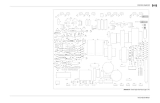
- 1. Schematics Supplement Force 2 Service Manual S-15 1 Schematic 12. Power Supply board layout, page 1 of 2
- 2. Schematics Supplement Force 2 Service Manual S-16 2 Schematic 13. Power Supply board layout, page 2 of 2
- 3. Schematics Supplement Force 2 Service Manual S-17 3 Schematic 14. Power Supply board, page 1 of 6
- 4. Schematics Supplement Force 2 Service Manual S-18 4 Schematic 15. Power Supply board, page 2 of 6
- 5. Schematics Supplement Force 2 Service Manual S-19 5 Schematic 16. Power Supply board, page 3 of 6
- 6. Schematics Supplement Force 2 Service Manual S-20 6 Schematic 17. Power Supply board, page 4 of 6
- 7. Schematics Supplement Force 2 Service Manual S-21 7 Schematic 18. Power Supply board, page 5 of 6
- 8. Schematics Supplement Force 2 Service Manual S-22 8 Schematic 19. Power Supply board, page 6 of 6
- 9. Schematics Supplement Force 2 Service Manual S-23 9 Schematic 20. Interface board layout
- 10. Schematics Supplement Force 2 Service Manual S-24 10 1% +12V R73 11K C53 .1 +12V PWOSC 5 4 U10B 4049 3 2 1 8 U10A 4049 C55 240PF 1% TP1 1 R72 51.5K 7 6 U10C 4049 ALL RESISTORS ARE +/- 5% .25W AND ALL CAPACITORS ARE +/- 10% AND THEIR VALUES ARE IN MICROFARADS THEIR VALUE IS GIVEN IN OHMS 9 10 U10D 4049 11 12 U10E 4049 C67 .001 C66 .001 HNSW FTSW/BIP 02 01 +12V PW OSC ISO-BLOCK 03 1 4 1 5 U10F 4049 DENOTES AN INVERTED SIGNAL. C62 .001 C12 1.0 2 1 3 Q1 2N3904 2 1 3 Q2 2N2907 1 2 CR3 1N4148 1 2 CR4 1N4148 -5V C13 1.0 VO 3 VI 2 G N D 1 U2 LM7905L -5V FOR DISPLAY BOARD ALSO C14 1.0 +5V SPARES 9 8 14 U1C LM339 -5V D 9 Q 13 CLK 11 Q 12 R 10 S 8 V D D 7 V C C 1 4 U3B 4013 C18 .1 C21 .1 Schematic 21. Interface board, page 1 of 3
- 11. Schematics Supplement Force 2 Service Manual S-25 11 BOUT1 1 2 3 RELAY +12V C54 1.0 6 3 5 4 1 2 K3 +12V C47 1.0 4 1 3 2 K2 +12V 1 4 2 3 K1 6KV C60 .0047 C16 .0047 BPRF1 BRF2 MONRF 1 2 3 4 5 6 7 J5 C59 .0047 RFRET +12V 10KV 10KV C17 .0047 C19 .1 R48 820 1 2 CR11 1N4148 R49 820 C39 1.0 R50 820 2 1 3 Q4 2N3904 R51 820 1 2 CR10 1N4148 2 1 3 Q3 2N3904 R52 820 R42 820 1 2 CR14 1N4148 2 1 3 Q5 2N3904 ACACT HSACT HSRLY ACRLY BPRLY REMF +12V TP5 1 R43 5.1K +12V 1% 11 12 U9E 4049 R69 19.1K +12V 9 10 U9D 4049 R70 33K R76 100K R37 24K C70 10 R38 27K 12 13 11 U4D 4011 8 9 10 U4C 4011 5 6 4 U4B 4011 +12V R21 10K 1 2 3 1 4 7 U4A 4011 C20 1.0 RMSW2 10KV RMRT1 RMRT2 1 2 3 4 5 6 J7 C58 .22 4 1 2 5 3 T3 R65 5.6K R64 15K R75 15K IN2 4 C2 5 OUT3 9 C3 6 OUT1 2 C1 13 IN4 11 C4 12 OUT4 10 IN1 1 IN3 8 OUT2 3 +5V 14 GND 7 U11 4066 1% R26 10K R34 10K 3 2 1 8 4 U5A LM358 C23 .1 1 TPGNDA +12V 9 8 14 U8C LM339 R67 390K 1 2 CR8 1N4148 REM R45 5.1K 11 10 13 U8D LM339 R44 68K 1 2 CR9 1N4148 R41 10K EREM 1% TP3 1 C42 1.0 R68 10K R47 10.2K R46 887 1% CR12 6.0V 1% -5V C24 .1 R27 200K 3 1 2 R15 5K 1% +5V R74 5.6K C61 .22 R77 220 FREQ 1 3 2 R11 +5V R30 6.04K 1% 9 1 0 U6D 4049 -5V C69 .1 R31 15K C30 10 1% TRIP C35 10 R35 15K R36 200K R14 1K 1% R53 10K R71 10K +12V +12V R57 470K 7 6 1 U8B LM339 R56 5.1K 1% TP2 1 +12V +5V R54 100K R66 887 C57 1.0 R40 3.3K +12V R23 560K 5 6 7 U5B LM358 1 R22 100K R17 200K 3 1 2 R16 ROSC TP4 C33 .1 1 1 1 2 U6E 4049 -5V 5 4 U6B 4049 C34 240PF 3 2 1 8 U6A 4049 C38 .1 7 6 U6C 4049 -5V D 5 Q 1 CLK 3 Q 2 R 4 S 6 U3A 4013 PW C22 .01 100K R24 910K R25 160K 5 4 2 3 1 2 U8A LM339 C44 .01 R55 10M REMPW REMPW J4 Schematic 22. Interface board, page 2 of 3
- 12. Schematics Supplement Force 2 Service Manual S-26 12 DIGIT L GND +5V 3 +5V 4 +12V 5 +12V 6 -5V 7 ANALOG GND 8 ECON VOLTAGE 9 ICON VOLTAGE 10 REM FAULT 11 RF SENSE 12 PWR ALARM 13 PWR ALARM 14 VOLUME (1) 15 VOLUME (2) 16 DIGITAL GND 17 DIGITAL GND 18 BIPOLAR ENABLE 19 CUT ENABLE 20 COAG ENABLE 21 BLEND ENABLE 22 BIPOLAR RELAY 23 HNDSW RELAY 24 ACCS RELAY 25 CUT RELAY 26 REM PULSE WIDTH 27 DIGITAL GND 28 HNDSW CUT 29 HNDSW COAG 30 HNDSW U/D 31 ACCS CUT 32 ACCS COAG 33 FTSW CUT 34 FTSW COAG 35 BIPOLAR FTSW 36 DIGITAL GND 37 DIGITAL GND 38 RF T (1) 39 RF T (0) 40 -5V C15 10UF 1 2 3 4 OPT3 OPI1264B 1K 14 15 U7F 4049 R7 3K 5 4 2 3 1 2 U1A LM339 R8 1K C1 1.0 C6 1.0 C2 .1 C7 1.0 10 1 2 3 J1 HSSCG HSSCT C8 1.0 R6 1K 1 2 CR1 1N4148 R1 1K C3 .1 R9 1K C5 .1 11 10 13 U1D LM339 +5V +5V 1 2 3 4 OPT2 OPI1264B R18 1K R20 3.6K 3 2 1 8 U7A 4049 REMF BPRLY HSRLY ACRLY REMPW HSWCT HSWCG HSWUD ASWCT ASWCG C51 .1 C43 .1 R59 1K +5V 1 2 3 4 OPT1 OPI1264B R12 1K R13 3.6K 5 4 U7B 4049 7 6 1 U1B LM339 C11 .1 R5 5.1K C9 1.0 1 2 CR2 1N5240B 1 2 CR6 1N5240B +12V C63 .0033 C40 1.0 2 1 6 3 5 4 7 T1 HNSW 2 3 1 Q6 VN10KM ACACT ACACT 1 2 CR5 1N4148 C26 1.0 1 2 3 J3 C29 1.0 C25 1.0 R3 4.3K C27 1.0 C4 .1 R4 1K C10 .1 +5V 1 2 3 4 OPT4 OPI1264B R10 3.6K R32 1K +5V 1 2 4 5 OPT7 4N35 R60 2.4K +5V C56 .1 3 2 1 8 U9A 4049 C50 .1 5 4 U9B 4049 +5V 1 2 4 5 OPT9 4N35 R58 1K +5V 1 2 3 4 OPT5 OPI1264B R29 1K R28 3.6K 11 12 U7E 4049 C32 .1 C31 .1 TPGND ACCCG ACCCT C28 1.0 1 2 3 4 5 6 J6 MONO CT MONO CG MONO CM BIP CM BIP DS 9 10 U7D 4049 R33 3.6K 1 2 4 5 OPT8 4N35 R62 2.4K R61 1K C52 .1 ISO-BLOCK 7 6 U9C 4049 +5V +5V R63 3.6K 1 2 3 4 OPT6 OPI1264B C36 .1 R39 1K C65 1.0 1 2 CR16 1N5240B C48 .1 +12V 2 1 6 3 5 4 7 T2 1 2 CR15 1N4148 C49 .1 C64 .1 C41 .1 FTSW/BIP 2 3 1 Q7 VN10KM C71 .0033 C68 1.0 1 2 CR13 1N4148 C37 1.0 1 2 CR7 1N5240B BOUT1 BIPSW Schematic 23. Interface board, page 3 of 3
- 13. Schematics Supplement Force 2 Service Manual S-27 13 Schematic 24. Monopolar Control/Display board layout
- 14. Schematics Supplement Force 2 Service Manual S-28 14 Schematic 25. Monopolar Control/Display board, page 1 of 13
- 15. Schematics Supplement Force 2 Service Manual S-29 15 Schematic 26. Monopolar Control/Display board, page 2 of 13
- 16. Schematics Supplement Force 2 Service Manual S-30 16 Schematic 27. Monopolar Control/Display board, page 3 of 13
- 17. Schematics Supplement Force 2 Service Manual S-31 17 Schematic 28. Monopolar Control/Display board, page 4 of 13
- 18. Schematics Supplement Force 2 Service Manual S-32 18 Schematic 29. Monopolar Control/Display board, page 5 of 13
- 19. Schematics Supplement Force 2 Service Manual S-33 19 Schematic 30. Monopolar Control/Display board, page 6 of 13
- 20. Schematics Supplement Force 2 Service Manual S-34 20 Schematic 31. Monopolar Control/Display board, page 7 of 13
- 21. Schematics Supplement Force 2 Service Manual S-35 21 Schematic 32. Monopolar Control/Display board, page 8 of 13
- 22. Schematics Supplement Force 2 Service Manual S-36 22 Schematic 33. Monopolar Control/Display board, page 9 of 13
- 23. Schematics Supplement Force 2 Service Manual S-37 23 Schematic 34. Monopolar Control/Display board, page 10 of 13
- 24. Schematics Supplement Force 2 Service Manual S-38 24 Schematic 35. Monopolar Control/Display board, page 11 of 13
- 25. Schematics Supplement Force 2 Service Manual S-39 25 Schematic 36. Monopolar Control/Display board, page 12 of 13
- 26. Schematics Supplement Force 2 Service Manual S-40 26 Schematic 37. Monopolar Control/Display board, page 13 of 13