08448380779 Call Girls In Civil Lines Women Seeking Men
Hfc o cli seminar
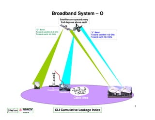
1. Broadband System – O
Satellites are spaced every
2nd degrees above earth
"C" Band
Toward satellite 6.0 GHz "L" Band
Toward earth 4.0 GHz Toward satellite 14.0 GHz
Toward earth 12.0 GHz
TV
TRANSMITTER
Headend
Cable area
1
CLI Cumulative Leakage Index
4. Ingress / Egress
Ingress:
RF signal leaking into the coaxial plant.
Egress:
RF signal leaking out of the coaxial plant.
4
5. Reasons to monitor leakage
1. Prevent Off-Air Broadcast Interference.
2. To meet government compliance.
3. To give our customer better quality of signal.
5
6. Spectrum Charts
108 MHz. 118 MHz 137 MHz
Off-Air Air navigation Air voice communications
Cable Ch: 98 - 99 Ch: 14 - 15 - 16
144 MHz. 162 MHz 174 MHz
Off-Air Ham Operators Government mobile
Cable Ch: 18 - 19 - 20 - 21 - 22
6
7. Spectrum Charts
225 MHz. 400 MHz.
Off-Air Military Air voice communication
Cable Ch: See below.
•155.34 MHz - Nationwide Hospital / Ambulance Radio Link
•156.80 MHz - Marine Emergency Aircraft Survival Locator.
•243.00 MHz - Emergency Aircraft Survival Locator.
7
8. Signal Leakage History
• Mid-band expansion.
• Aeronautical interference discover (1976)
• Frequency offsets (1979)
• Radian dome (1980)
• Mandatory FCC / DOC enforcement (1980s)
• Cumulative Leakage Index (1990)
8
9. Cumulative Leakage Index CLI
CLI is the net effect of the combination of all
the leaks in the system added together.
These cumulative leaks form an invisible cloud
of unwanted RF energy over the cable system.
9
10. CLI Rules (Quarterly)
•Ride out 100% of system and log all leaks.
•Log should include Date found and Date fixed.
•Documenting leakage level isn't required for this drive out.
•Actual practice for your system may vary!
10
11. CLI Rules (Annually)
•Ride out 75% of the oldest part of the system and log all leaks
location and measured level.
•Must be performed within a reasonable period of time
(Usually within 2 wks of due date)
•Actual practice for your system may vary!
11
12. The only acceptable procedure for leakage
measurement by the government rule.
•Use a calibrated half wave dipole antenna.
•Antenna must be elevated 3 meters off the ground and
positioned 3 meters from the leakage source.
•Antenna must be rotated 360° in the horizontal plane for
maximum reading.
12
13. Required actions.
•All leaks above 20uV/m must be logged and fixed.
•Only leaks above 50uV/m are used in CLI calculation.
•All measurements taken outside 108 – 137 MHz must be
converted as if they were taken within the band.
13
14. uV/M (Microvolts per Metre)
•Standard unit of measure for CLI
•50 Ohm off air measurement.
•Voltage developed in 1 meter of infinitely, this section of
wire submerged in a leakage field produces 1uV of energy.
14
15. C.L.I.
•Cumulative Leakage Index.
•Mathematical summation of leakage in a system designed to
approximate the interference to aircraft flying overhead.
•Figure of merit for system performance.
•One leak of 1588uV/M within a system is enough to fail C.L.I.
15
17. BP-23 for Canadian Operator.
3.2 Leakage Control
3.2.1 At all times, cable system operators should strive to minimized emanating
from their facilities.
3.2.2 The operator of a cable television system distributing signals over
supplementary channels must carry out a systematic patrols to detect leakage, and
take corrective measures to prevent leakage.
3.2.3 The operator of a cable television system must keep a logbook indicating
the date and location foe each leak detected, the date on which it was repaired and its
probable cause. This logbook must be kept for a period of two years so that it may be
examined by an inspector from the Department upon request.
3.2.4 When leakage originates from a subscriber’s premises, the system operator
must ensure the necessary repairs are carried out. If such repairs cannot be effected
within a reasonable period of time, the operator must stop distribution of the
interfering service(s) or channel(s) to the subscriber’s premises until the leakage can
be repaired. In addition, distribution of interfering of service(s) or channel(s) to
subscriber’s premises must be stopped immediately if the leakage originating from
the subscriber endanger safety services (ambulance, police, aeronautical frequencies,
and so on)
17
18. BP-23 for Canadian Operator.
4.1 General Provisions
4.11 Unless indicated otherwise, all technical standards stated herein apply to the
requirements respecting performance between the cable television system input and
any subscriber terminal.
4.1.2 All technical standards specified herein relate to the measurement procedure
discussed in this document, and, where appropriate, apply in the presence of all
signals usually carried on the system.
4.2 Leakage Criteria
4.2.1 The following leakage criteria are used to evaluate cable system leakage
performance.
4.2.2 The Equivalent Leakage Density estimates the impact of signal leakage on
land-based radio system- I.e. police, ambulance service, etc.- which share spectrum
with cable television systems. The ELD criterion ensures that all cable systems meet a
leakage performance intended to minimize interference to land-radio system.
4.2.3 The Cumulative Leakage Index (CLI) estimates the cumulative impact of
leakage on aeronautical spectrum users. When the signal leakage measurements are
taken on the ground, the CLI ground-based criterion (CLIg) is used. If the
measurements are taken in the airspace above the cable system, the CLI air-based
criterion (CLIa) is used to estimate this impact. Both criteria apply to cable system
carrying A-1(99), A-2(98), EE941) and FF(42)
18
19. BP-23 for Canadian Operator.
http://strategis.ic.gc.ca/epic/internet/insmt-gst.nsf/vwapj/bpr8e.pdf/$FILE/bpr8e.pdf
You can get this procedure at the above internet link
19
20. BP-23 for Canadian Operator.
4.3 Equivalent Leakage Density (ELD)
For the purposes of calculating the Equivalent Leakage Density,
leakage readings are classified into three categories, each of which
has it corresponding weighting factor, as shown in the table below.
20
21. BP-23 for Canadian Operator.
4.3.2 The ELD is calculated using the following formula:
ELD = (N1 X 1) + (N2 X 2) + N3 X 3),
K
where:
ELD = Equivalent Leakage Density
N1 = Number of leaks in Category A (50 – 220 uV/m)
N2 = Number of leaks in Category B (201 – 500 uV/m)
N3 = Number of leaks in Category C (>500 uV/m)
1 = Category A weighting factor
2 = Category B weighting factor
3 = Category C weighting factor
K = Number of kilometres patrolled.
4.3.3 For the purposes of ELD calculations, only leaks equal to or
grater than 50 uV/ at 3 metres need to be taken into account.
21
22. BP-23 for Canadian Operator.
4.4 Equivalent Leakage Density Application Schedule.
Table 4.2 shows the ELD limits applications schedule. The beginning
of the first implementation period coincides with the effective date of
this document. Cable systems will have to the end of each
implementation period to reach the ELD limit that applies for that
period. The maximum limit after 6 years is 0.8.
22
23. BP-23 for Canadian Operator.
4.5 CLI Ground-Based Criterion (CLIg)
4.5.1 The computed CLIg must not be over 64.
4.5.2 The CLIg is calculated using the following formulas:
Where:
CLIg = CLI ground-based criterion, taking into the surface area of
the system
F(S) = Correction factor for the surface area
Ei = Filed strength of the ith leak measured at 3 metres, in uV/m
S = Surface area covered by the cable system in km²
N = Number of leaks detected
4.5.3 While all leaks, regardless of magnitude, must be
repaired, it is not necessary to take into account leaks of less than
50 uV/m at 3 metres when calculating the CLIg 23
24. BP-23 for Canadian Operator.
4.6 CLI Air-Based criterion (CLIa)
The CLIa is the 90th-percentile value of the field strength due to
cable leaks and it must not exceed 10 microvolts per metre RMS at
an altitude of 450 metres above the cable system’s average ground
level.
4.7 Carrier-to-Noise ratio
The carrier-to-noise ration for each television channel received at
any subscriber terminal must not be less than 40 dB.
The full BP-23 can be downloaded at the internet address below:
http://strategis.ic.gc.ca/SSG/sf01209e.html
24
26. Calibrating Leakage Detection Equipment.
1. Connect calibrated signal source set at 20uV/m.
2. Position the dipole antenna.
3. Adjust to read 20uV/m.
26
28. Causes of Signal Leakage (1).
80% of all leakage is caused by problems
between the tap and entry to the house.
•Aging and environmental stress.
•Physical trauma to cables or connectors.
•Loose drop connectors.
•Inferior quality coaxial cable, passives, or connectors.
•Loose hard line connectors.
28
29. Causes of Signal Leakage (2).
•Improperly installed connectors.
•Cracks in the trunk and feeder cable.
•Animal chews.
•Poorly-shielded drop cable.
•Bad connectors at the tap.
•Corroded connectors.
29
30. Causes of Signal Leakage (3).
•Customer installed equipment.
•Damaged amplifier housing or loose amplifier housing lid.
•Broken tap ports.
•Poor installation of splices and connectors.
•Poorly-shielded customer premise equipment.
30
31. Problems Caused by Ingress.
•Lines in pictures.
•Ghosting.
•Pay per view problems.
•High speed data problems.
•De-scrambling problems.
•Interference with two-way radio services using the
same frequencies.
31
32. Problems Caused by Ingress in digital channels.
•Mosaic.
•Freeze frame.
•Picture and sound to black.
32
34. Accessories for the Super Plus.
Vehicular
Antenna
AVM-2 108 to
AVM-
118 MHz AVM-3
AVM-
118 to 157 MHz
Half Wave Dipole
can be extended to
20 feet
34
35. Accessories for the Super Plus.
Half wave fixed frequency dipole 50
ohms impedance.
Extends to the require 10 feet for CLI
measurements.
Order frequency: 108 to 157.25 MHz.
35
36. Accessories for the Super Plus.
Near-field probe for close-in
detection of signal leakage.
36
37. Accessories for the Super Plus.
The solution to “False Alarms”
Give low-frequency modulation, ignored by the TV sets, but causes a
distinctive response to TRILITHIC Searcher Plus and Super Plus.
When use it eliminates all “false alarm” triggers and increases leak
detection sensitivity by four times over previous models.
37
38. Dipole Antenna Radiation Patterns.
Pattern of the dipole antenna
installed in the roof of the truck
doing CLI testing.
38
40. Finding Leakage.
Leak Tones
DISTANCE = 10ft or less
SENS
use: x10 setting
X1
(remember to multiply
X10
settings by 10)
uV/M
SENS
DISTANCE = 100ft or less
X1
use: x1 setting
X10
uV/M
DISTANCE = 400ft or less SENS
X1
use: SENS setting
X10
uV/M
40
42. Interesting web sites.
Below are web sites where you can get technical information on
CATV and HFC systems. Most of these sites are from University
and are free.
http://cable.doit.wisc.edu/cable_resources.html
http://www.itcom.itd.umich.edu/cabling/fib-glos.html
http://whatis.techtarget.com/definitionsAlpha/0,289930,sid9,00.html
42
43. Interesting web sites.
Below are web sites of all the majors CATV and FIBER
OPTIC and COAXIAL CABLES supplier.
http://www.acterna.com/
http://www.aflfiber.com/
http://www.alphatechnologies.com/
http://www.amcomm.com/
http://www.amphenol-catv.com/catvfamsearch1.cfm
http://www.c-cor.net/
http://www.commscope.com/html/home.shtml
http://www.corning.com/OpticalFiber/
http://www.electrolinequip.com/en/about_us/faq/index.html
http://www.corning.com/corninggilbert/
http://www.lindsayelec.com/lspa.html
43
44. Interesting web sites.
Below are web sites of all the majors CATV and FIBER OPTIC
and COAXIAL CABLES supplier.
http://www.gi.com/
http://www.nettest.com/
http://www.ofsoptics.com/NASApp/cs/ContentServer?pagename=ofsoptics/templates/ofsopticsmain
http://www.powerware.ca/
http://www.ppc-online.com/main2.cfm
http://www.timesfiber.com/
http://www.trilithic.com/
http://www.visionteq.com/
http://www.wavecom.ca/
44