2. Basic parts of Internal Combustion Engine
a) Cylinder head
top of the engine which contain a hole for valves
valves, intake and exhaust passages, cooling
passages
b) Valves
open and close to let fuel air mixture (petrol
engine) or air only (diesel engine)
exhaust gases out of each cylinder
c) Camshaft
rotates to open and close the valves by cam action
3.
4. d) Cylinder block
Main housing of the engine and supports other main parts
Contain cylindrical vessels in which combustion takes place
and piston makes a reciprocating motion
e) Cylinders
Hollow tubes, piston moves back and forth
f) Pistons
Move in the cylinders and apply the force of combustion to
crankshaft
g) Piston rings
A component that fitted into the slot around the piston which
seal the combustion chamber and help transfer heat
5.
6. h) Connecting rods
A rod that interconnect the piston and the crankshaft
and transmit the forces from the piston to crankshaft
i) Crankshaft
Receives the force from pistons and transmit as rotary
driving power
j) Main bearings
Support crankshaft in cylinder block
k) Flywheel
Attach to crankshaft at rear, provides momentum and
help return pistons to the top of cylinders
7.
8. l) Timing drives
Link the crankshaft, camshaft and other parts
together to assure each is doing its job at the right
time
m) Cams
Integral part of camshaft design to open the valve
at the correct timing and to keep them open for the
necessary duration
n) Gudgeon pin
Forms the link between the small end of the
connecting rod and the piston
12. Comparison Between Petrol and
Diesel Engine
a. Fuel Supply and Ignition
b. Compression Ratio
c. Design of Engine Parts
d. Grade and Type of Fuel Used
13. a) Fuel Supply and Ignition
Petrol Engine
Fuel and air mixed outside the cylinders in the carburetor and
intake manifold
Mixture is forced into cylinders by partial vacuum created by
intake stroke of piston
Uses electric spark to ignite fuel air mixture
Compression ratio 8 to 1 (8:1)
Diesel Engine
No premixing of air and fuel
Air taken into cylinders through intake manifold and compressed
Fuel is sprayed into cylinders and mixed with air as the piston
nears the top of its compression stroke
Use heat and compressed air for ignition
Compression ratio 16 to 1 (16:1)
14. b) Compression Ratio
Compression ratio is a characteristic of an engine
i.e. related to engine efficiency i.e. the ability of the
engine to convert in the fuel to useful mechanical
energy
The greater the compression ratio, the greater the
potential efficiency of the engine
Compares volume in cylinder before compression
with volume after compression
High compression ratio of diesel – cause high
temperature of air to ignite fuel without a spark
Therefore diesel engine more efficient because
higher compression i.e greater expansion of gases
in cylinder therefore more powerful stroke
15. c) Design of Engine Parts
Engine of diesel more sturdier parts to
withstand greater forces
16. d) Grade and Type of Fuel Used
• Diesel fuel -- more heat units (joule) per
gallon
• Therefore produces more power per gallon of
fuel
– fuel low cost but fuel injection equipment is more
expensive than petrol equipment
17. Comparison between Engines
Diesel Petrol
1. Fuel efficiency Best Fair
2. Time before maintenance Good Fair
3. Weight per horse power High Low
4. Cold weather starting Fair Good
5. Acceleration Good Good
6. Continuous Duty Good Fair
7. Lubricating oil contamination Moderate Moderate
18. DIESEL ENGINE PETROL ENGINE
1. Fuel System 1. Fuel System
Use diesel Use petrol
No carburetor Have carburetor
Uses heat & compressed air Uses electric spark to ignite
for ignition air‐fuel mixture
2. Higher compression ratio 2.Lower compression ratio
14 – 16 : 1 7 – 10 : 1
3. Operation 3.Operation
No pre‐mixing of air and fuel Fuel and air mixed outside the
Air taken into cylinder cylinders in the carburetor
through intake manifold and and intake manifold
compressed Mixture is forced into
Fuel is sprayed into cylinders cylinders by partial vacuum
and mixed with air as the created by intake stroke of
piston nears the top of its piston
compression stroke
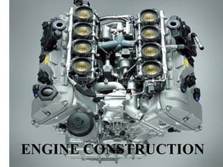
19. Engine Construction
Functions
1. Valves - Intake and Exhaust Valves
The valves allow fuel-air in and exhaust gases out of each
cylinder during combustion cycle by opening and closing the
intake and exhaust parts of the cylinder.
Intake Stroke
Intake valve opens allowing fuel air mixture to enter
combustion chamber
Compression and Power Stroke
Both valves are closed to seal in combustible mixture
Exhaust Stroke
Exhaust valve opens allowing gases to be exhausted
End of Exhaust Stroke
Intake valves opens, beginning another cycle
20. 2. Camshaft
• is turned by the engine crankshaft.
• A lobe (cam) on the camshaft causes the cam
follower and push the rod to push the valve open
• The spring closes the valve when the cam allows
the push rod and cam follower to return to low
side of the cam
• Cam movements are designed to open or close the
valves at the right moment
21. 3. Engine Crankcase and Cylinder Block
• Made of iron casting and is an integral with
cylinder block which houses cylinder liners
• Liners are said to be wet or dry according to
whether they are or not in contact with cooling
water that circulate through engine block
• Crankcase houses the crank gear and valve gear
22. 4. Engine Block
• Houses the injection pump, oil pump, water pump
and power generator
• The front part carries the timing cover, rear end
carries clutch bell housing on which the starter
motor is mounted
• Provided with oil filler cap and breather, oil
dipstick and water connection to the radiator
23. 5. Cylinder Head
Consists of fuel injectors , inlet and outlet valves, the rockers
Cylinder head is in a single piece for engines up to 4 cylinders
Between cylinder head and engine block – cylinder head
gasket; to prevent gas, coolants and lubricating oil from
escaping
Also connected the inlet and exhaust manifolds water pipe from
radiator
6. Oil Sump
Made of iron casting
Seals the crankcase at the bottom
Functions as a reservoir for the lubricating oil
24. 7. Piston, Connecting Rod & Cylinder Liners
Piston
move in the cylinders and apply the force of combustion to
the crankshaft
Combustion chamber machined in upper part known as
piston head or crown ; lower part known as piston skirt
Connecting rods
Transmit the motion of the pistons to the crankshaft
Cylinder Liners
made of cast iron
may be wet or dry; wet liners can be inserted and removed
by hand; dry liner removal and installation with the use of a
press (of a few tons capacity)
25. 8. Crankshaft
Receive the force from the pistons and transmits it as rotary driving
force
Rear end carries the flywheel incorporating starter ring gear
Front end carries crankshaft gear used to drive valve timing
mechanism, oil pump
9. Flywheel
Attaches to crankshaft at rear & provides momentum to help return
the pistons to the top of cylinders after each downward thrust
10. Timing Drives
Link the crankshaft, camshaft and other parts together so that each
is doing its job at the right time
26. What is Internal and External
Combustion Engines
• Internal Combustion Engine
– Form of heat engine because heat engine produced
by the burning of fuel within the engine is changed
into mechanical energy
• External Combustion Engine
– Heat energy is supplied from external source in the
form of steam from boiler outside the engine
27. Adjusting Valve Clearance
• Proper valve maintenance is necessary so that engine
works efficiently and not be damaged
• When valves are properly adjusted, there is a small
clearance between valve stem and end of rocker arm
• This clearance is referred to as Valve Clearance or
tappet clearance
28. Valve Clearance
• Allows for heat expansion of valve operating
parts
• Without clearance, “tehe” heated parts would
cause the valves to stay partly open during
operation & engine would lose compression &
power
• The valve clearance is small, approx: 0.15-0.75
mm. Valve clearance varies with different engine
model; whether the engine should be hot or cold
during adjustment
29. Effects of Too Small Valve Clearance
• Caused the valve out of timing
• Valves open too early & close too late
• Valves stems may lengthen from heating & prevent
valves from seating completely.
• Hot combustion gases rushing past the valves cause
overheating because the valves seat so poorly that
normal heat transfer into the cooling system does not
have time to take place
• This causes Burned Valves
30. Effect of Too Big Valve Clearance
• Causes a lag in valve timing which made the engine
out of balance
• Fuel air mixture is late in entering the cylinder during
the intake stroke
• Exhaust valve closes early & prevents waste gases
from being completely removed
• This causes Valve Damaged
31. Why Proper Valve Adjustment is
Important
• Engine will use fuel more efficiently
• Engine will start more easily
• Maximum power will be achieved
• Valves will give longer service
• Overheating of engine is less likely to occur
32. Adjusting Valve Tappet Clearance
– Check valve tappet clearance every 500 hours
of operation or at interval indicated in
operator’s manual
Valve Timing
– Opening and closing of both inlet and exhaust
valves when the piston is at the exact top
(TDC) or bottom (BDC) of its stroke
Valve Overlap
– Both valves are open at once at the same period
33. WHAT IS ENGINE
• Is a structure that converts chemical energy
(fuel) to mechanical energy.
• Usually made available on a rotating output
shaft.
• Normal engine that been used on road is
known as Internal Combustion Engine (IC)
• Is a reciprocating engines that have pistons
that move back and forth in cylinders within
the engine.
34. ENGINE CLASSIFICATIONS
1. Types of ignition
a) Spark Ignition (SI)
An engine starts the combustion process in each cycle
by using spark plug.
The spark plug gives high-voltage electrical discharge
between two electrodes which ignites the air-fuel
mixture.
Before spark plug been used torch holes been used
(external flame)
35. b) Compression ignition (CI)
CI engine starts when the air-fuel mixture self-ignites
due to high temperature in the combustion chamber
due to high compression.
2. Engine cycle
a) Four stroke cycle
A four-stroke cycle experiences four cycle movement
over two engine revolutions for each cycle.
b) Two stroke cycle
A two-stroke cycle has two cycle movement over one
revolution for each cycle.
36. 3. Valve location
a) Valves in head (overhead valve), known as I
head engine.
b) Valves in block (flat head), known as L head
engine.
c) One valve in head (intake) and one in block,
known as F head engine.
37. 4. Basic design
a) Reciprocating
Engine has one or more cylinders in which pistons
move back and forth.
The combustion chamber is located in the closed end of
each cylinder.
b) Rotary
Engine is made of a block built around a large non-
concentric rotor and crankshaft.
Combustion chambers are built into the nonrotating
block.
38. 5. Position and number of cylinders of reciprocating
engines
a) Single cylinder
Engine has one cylinder and piston connected to the
crankshaft.
b) In-line
Cylinders are positioned in a straight line.
One behind the other along the length of the crankshaft.
They can consist of 2 to 11 cylinders or more
Common are four cylinders engine
39. c) V engine
Two banks of cylinder at an angle with each other along
a single crankshaft.
The angle are 15⁰ to 120⁰, common are 60⁰ to 90⁰
2 to 20 cylinders, normally V6s and V8s
V12s and V16s for luxury and high performances
vehicles.
d) Opposed cylinder engine (crankshaft at
middle)
Two banks of cylinders opposite each other on a single
crankshaft (a V engine with a 180⁰ V).
Used for small aircraft, known as flat engine.
40. e) W engine
Same as V engine except with three banks of cylinders on the
same crankshaft.
Normally developed for racing automobiles.
f) Opposed piston engine
Two pistons in each cylinder with the combustion chamber in
the center between the piston.
A single-combustion process causes two power strokes at the
same time. Each piston pushed away from the center and
delivering power to a separate crankshaft at each end of the
cylinder.
g) Radial engine
Engine with pistons positioned in a circular plane around the
central crankshaft.
The connecting rods of the pistons are connected to a master
rod which, in turn, is connected to the crankshaft.
41.
42. ENGINE COMPONENTS
LAB 2
1. Block 16. Glow plug
2. Camshaft 17. Cylinder head
3. Carburetor 18. Head gasket
19. Intake manifold
4. Catalytic converter 20. Main bearing
5. Combustion chamber 21. Oil pump
6. Connecting rod 22. Piston
7. Crankcase 23. Piston rings
8. Crankshaft 24. Push rods
9. cylinders 25. Radiator
26. Spark plug
10. exhaust manifold
27. Speed control-cruise control
11. exhaust system 28. Starter motor
12. fan 29. Throttle
13. flywheel 30. turbocharger
14. fuel injector 31. Water jacket
15. Fuel pump 32. Water pump
45. Four Stroke SI Engine Cycle
Intake Valve Exhaust Valve 4
1 2 Exhaust 3
Intake
Manifold Manifold
Spark
Cylinder Plug
Piston
Connecting
Crank
Rod
Crankcase
Power Stroke Exhaust Stroke
Intake Stroke Compression Stroke
Fuel-air mixture burns, Exhaust valve open,
Intake valve opens, Both valves closed,
increasing temperature exhaust products are
admitting fuel and air. Fuel/air mixture is
and pressure, expansion displaced from cylinder.
Exhaust valve closed compressed by rising
of combustion gases Intake valve opens
for most of stroke piston. Spark ignites
drives piston down. Both near end of stroke.
mixture near end of
valves closed - exhaust
stroke.
valve opens near end
of stroke