
Recomendados
Mais conteúdo relacionado
Semelhante a Anaesthetic Machine Anatomy.pdf
Semelhante a Anaesthetic Machine Anatomy.pdf (20)
Último
Último (20)
Anaesthetic Machine Anatomy.pdf
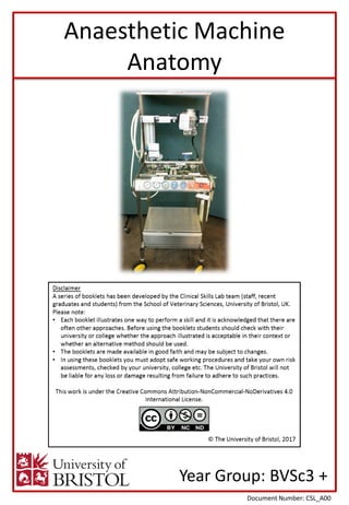
- 1. Year Group: BVSc3 + Document Number: CSL_A00 Anaesthetic Machine Anatomy
- 2. Equipment for this station: Considerations for this station: Equipment list: Anyone working in the Clinical Skills Lab must read the ‘CSL_I01 Induction’ and agree to abide by the ‘CSL_I00 House Rules’ & ‘CSL_I02 Lab Area Rules’ Please inform a member of staff if equipment is damaged or about to run out. • Anaesthetic machine • Name labels • Function labels • Do not attempt to attach cylinders or connect the oxygen pipeline, this machine is for reference only and is NOT a working machine. • The first time you try to complete this task it may be worth refreshing your memory of the anaesthetic machine by reading the section of this booklet marked ‘Answers’. Anaesthetic Machine Anatomy
- 3. Clinical Skills: Using the name labels provided, name each part of the anaesthetic machine (match/stick the white square velcro tab to the yellow square tab). On the bottom of the name label, place a function label (match the circular tabs). On some of the function labels there are additional questions. Place the correct answers in the space provided (match the semi-circular tabs). You will need to lift the lid to find all of the components! Once you have placed all of the labels, use the information on the following pages of this booklet to check your answers. Here are some online resources and tutorials that you may find useful: 1. http://mhra.gov.uk/learningcentre/AnaestheticMachines/player.html 2. https://www.youtube.com/watch?v=1LY0eAzrIrE Anaesthetic Machine Anatomy 1 2 3 4 5
- 4. Anaesthetic Machine Anatomy ANSWERS ANSWERS: The following pages contain the answers i.e. the name and function of each part of an anaesthetic machine
- 5. Oxygen (O2) Check valve Pressure gauge Pressure regulator Pipeline oxygen (O2) Pipeline nitrous oxide (N2O) O2 failure alarm and reservoir N2O cut-off Flowmeter Vaporiser O2 flush Common gas outlet Schematic Diagram of an Anaesthetic Machine N.B. This diagram is simplified to aid in the understanding of the components. Anaesthetic machines have additional regulators and check valves to those shown above. Ensure you know the functions of each of the components named in the diagram. Anaesthetic Machine Anatomy Clinical Skills: Nitrous oxide (N2O)
- 6. Clinical Skills: 1 2 3 5 Gas source: • Cylinders (not included on this machine - do NOT attach) Cylinders attach via a yoke. The yoke: • Supports the cylinder • Provides a gas-tight seal (Bodok seal) • Allows unidirectional flow from the cylinder to the machine • Prevents the cylinder being attached to the wrong inlet (pin index system) The yoke contains a Bodok seal. The Bodok seal consists of a non-combustible neoprene washer with a copper ring. It ensures a gas-tight seal between the yoke and the gas cylinder. The yoke also prevents a cylinder being attached to the wrong inlet via the Pin Index Safety System. The yoke for each gas type has 2 protruding pins that match 2 holes on the respective gas cylinders. The placement of the pins (and holes) vary for each gas, with a potential 6 pin positions, shown above. Example pins on gas cylinders: • Oxygen (O2) has a pin index of 2 & 5 • Nitrous oxide (N2O) has a pin index of 3 & 5 4 Anaesthetic Machine Anatomy Yoke pin positions for an oxygen cylinder. 6
- 7. Clinical Skills: 7 9 10 11 12 Gas source: • Pipeline (do NOT attach the oxygen pipeline included on this machine to the wall outlet) Some practices use a pipeline system. Piped gas is drawn from a central source and fed into a labelled and colour-coded pipeline distribution network which terminates in self-closing Schrader sockets at the wall. Flexible pipelines connect the terminal outlet to the anaesthetic machine. Flexible pipelines have three components: 1. Schrader probe This prevents misconnection to the wrong gas service. Each gas probe has a protruding index collar with a unique diameter - this only fits the Schrader socket for the same gas type. 2. Flexible hosepipe Modern hoses are colour coded for each gas: • Oxygen – white • Nitrous oxide – blue • Medical air – black & white 3. Non-Interchangeable Screw Thread (NIST) This comprises of a nut and probe with a unique profile for each type of gas. It includes a one-way valve to ensure unidirectional flow. When a pipeline is used, it is good practice to have reserve cylinders available as a back- up. Anaesthetic Machine Anatomy 8 Schrader sockets
- 8. Clinical Skills: 13 14 15 16 17 Pressure regulator: Gas from cylinders is at very high pressure (>10,000 kPa) This pressure needs to be reduced to a safe level that will not damage the anaesthetic machine (approximately 400 kPa) The pressure regulator: • Reduces the cylinder pressure to a suitable supply pressure • Compensates as the cylinder content decreases This ensures a safe delivery of gas at a manageable pressure, whilst smoothing any fluctuations of pressure from the gas supply. Pressure gauges: The pressure gauges indicate the pressure of gas in kPa. If using cylinders, use the pressure gauge to determine when the cylinder is nearly empty (low pressure on gauge) and needs changing. Oxygen (O2) is stored as a gas in the cylinder. The pressure is proportional to the volume of gas in the cylinder. As the cylinder empties, the pressure gauge drops in a linear fashion. Nitrous oxide (N2O) is both liquid and gas in the cylinder. As N2O is used, liquid vapourises into the gaseous form and the pressure remains constant. Once the liquid is used up, the pressure falls quickly. As soon as the pressure gauge decreases, be aware that the cylinder is nearly empty. On this machine the pressure gauges can be identified for both the cylinders and the pipeline supply. Diaphragm Spring Valve Inlet from cylinder HIGH PRESSURE Outlet to machine LOW PRESSURE Anaesthetic Machine Anatomy
- 9. Clinical Skills: 19 20 Check valve: The check valve is a one way valve that prevents backflow of gas to the atmosphere or between cylinders on one machine. Anaesthetic Machine Anatomy O2 N2O input N2O output Inlet Outlet Valve Nitrous oxide cut off: The flow of N2O is dependent on oxygen pressure. When the O2 pressure falls past a certain threshold, the nitrous oxide supply is cut off. This threshold is between 130 kPa to 70 kPa, depending on the machine. This prevents the administration of a hypoxic gas mixture. Alarm Reservoir 18 O2 failure alarm: An alarm sounds when the pressure in the oxygen supply falls below 200 kPa. In this machine there is a reservoir of air used to supply the whistle alarm. N2O input N2O output O2
- 10. Clinical Skills: 21 23 24 25 26 Gas flow rate: To adjust the gas flow rate of a particular gas, rotate the respective flow control valve. Take care when adjusting these valves, the mechanism is delicate and can be broken by using too much force or closing the valve too firmly. Read the gas flow rate from: • The TOP of the bobbin (not the dot) • The MIDDLE of the ball (if a spherical ball is used in place of a bobbin) Some flowmeters have a built in hypoxic guard: The O2 and N2O control valves are linked mechanically. Either valve can be adjusted independently but the link maintains a minimal ratio of O2 : N2O. If you turned on the N2O alone, the O2 flowmeter is also operated so that 100% N2O is not delivered. If you turn the O2 off, the N2O is also turned off. In this way O2 can never be administered at less than 20-25% Flowmeter: Flowmeters measure the flow rate of a gas passing through them. They consist of: 1. A flow control valve 2. A tapered transparent tube 3. A lightweight rotating bobbin or ball 1. Flow control valves • Reduce gas pressure from 420 kPa to just above atmospheric pressure (1 atm or 100 kPa). • Allow fine adjustment of gas flow through the flowmeters by manual adjustment. 2. A tapered tube • Gas enters the tube when the valve is open. 3. A bobbin or ball • The bobbin floats within the tube as the gas flow passes around it. • The higher the flow, the higher the bobbin rises. Anaesthetic Machine Anatomy O2 flow- meter N2O flow- meter Link 22
- 11. Clinical Skills: 27 28 Vaporisers: This is situated on the back bar of the anaesthetic machine downstream of the flowmeter It contains the volatile liquid anaesthetic agent (e.g. isoflurane, sevoflurane). Gas is passed from the flowmeter through the vaporiser. The gas picks up “vapour” from the vaporiser to deliver to the patient. Most vaporisers are calibrated (see 28). Occasionally old anaesthetic machines have an uncalibrated vaporiser. These are simple and inexpensive but have been replaced by calibrated vaporisers as the vapour produced varies depending on temperature, gas flow rate and back pressure from a ventilator. Gas enters the chamber, picks up vapour and then exits the vaporiser. It is difficult to control the concentration of agent that is delivered. As the agent vaporises it will cool. The saturated vapour pressure will fall and so less agent is delivered. Calibrated vaporiser: • Designed to overcome flaws of simple model • Gas entering vaporiser is split into two streams - Bypass channel (does not contact anaesthetic) - Chamber above liquid anaesthetic • A control valve adjusts the ratio of gas that bypasses the vapour chamber to the gas that passes through the chamber. The concentration of the vapour being “entrained” (picked up) by the gas can be increased by adjusting this ratio. This valve is controlled by the large dial on the front of the vaporiser. • The vaporiser is housed in a large block of brass to minimise the effect of temperature cooling. • A bi-metallic strip is a secondary control point that adjusts the gas flow through the vaporiser. As the agent cools, the bimetallic strip moves, allowing a greater ratio of the gas to pass through the vapour chamber, entraining a greater concentration of volatile agent and mitigating the effect of temperature. Gas in Gas out Agent vapour Agent liquid Anaesthetic Machine Anatomy Gas in Gas out Agent vapour Agent liquid Bi-metallic Strip Control Valve Bypass Chamber Brass container
- 12. Clinical Skills: 29 30 31 32 33 34 Back bar: This is where the vaporiser(s) can be connected to the anaesthetic machine. Some anaesthetic machines have positions for more than one vaporiser, on these machines there are safety interlocks to prevent administration of 2 volatile agents simultaneously. Common gas outlet: This connects to the anaesthetic breathing circuit to deliver the combined product of gases and anaesthetic agent to the patient. It is also used by the oxygen flush, in the case of an emergency. O2 flush: This supplies O2 in an emergency directly from the high pressure circuit (bypassing the flowmeters and vaporiser). This is pure O2 at 35-60 L/min and does not contain anaesthetic agent. On this old machine it is possible to ‘hold’ the O2 flush - a dangerous function that is no longer possible on newer machines due to the risk of causing barotrauma (injury caused by pressure). Scavenging: Waste anaesthetic gases and volatile agents are subject to the Control of Substances Hazardous to Health and the Health and Safety at Work Act. “Scavenging” describes the removal of environmental contaminants to ensure that exposure limits are not exceeded (Isoflurane 50 ppm, N2O 50 ppm) There are 2 types of scavenging: 1. Active 2. Passive 1. Active Scavenging • Waste gases are drawn outside of the building via a fan and vent system. • An air break is necessary to prevent negative pressure being applied to the patient breathing system. • On this machine the top of the scavenger would attach to the breathing circuit, the bottom would connect to the wall outlet. 2. Passive Scavenging • No fan • Exhaled gas propelled by patient’s expiratory effort into tubing: i. Waste gas carried via tubing to outside of building (N.B. creates high resistance making it more difficult for patient to exhale). ii. Or waste gas absorbed in canister of activated charcoal (N.B. N2O is NOT absorbed by this method). • The canister should be weighed regularly to monitor lifespan and replaced when it reaches a particular weight. Anaesthetic Machine Anatomy Common gas outlet Activated charcoal canister Wall outlet
- 13. Resetting the station: Station ready for the next person: Please inform a member of staff if equipment is damaged or about to run out. 1. Ensure all the name and function labels have been removed from the machine 2. Return the labels to their containers 3. Replace the lid on the anaesthetic machine Anaesthetic Machine Anatomy
- 14. I wish I’d known: • It is essential that you know how an anaesthetic machine works – if something goes wrong during a general anaesthetic, you won’t have much time to figure it out! • Different machines will have slight differences, make sure that you are familiar with the machine you are using, before starting the anaesthetic. Anaesthetic Machine Anatomy