
Recommended
More Related Content
Similar to Radar vs ultrasonic level calibration points
Similar to Radar vs ultrasonic level calibration points (20)
More from Vohinh Ngo
More from Vohinh Ngo (20)
Recently uploaded
Recently uploaded (20)
Radar vs ultrasonic level calibration points
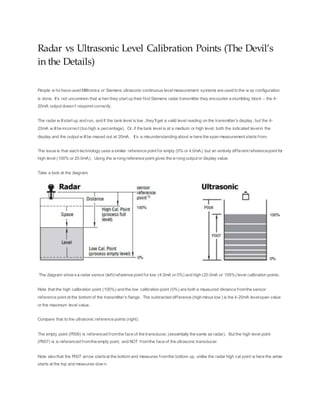
- 1. Radar vs Ultrasonic Level Calibration Points (The Devil’s in the Details) People w ho have used Milltronics or Siemens ultrasonic continuous levelmeasurement systems are used to the w ay configuration is done. It’s not uncommon that w hen they start up their first Siemens radar transmitter they encounter a stumbling block – the 4- 20mA output doesn’t respond correctly. The radar w illstart up and run, and if the tank level is low , they’llget a valid level reading on the transmitter’s display, but the 4- 20mA w illbe incorrect (too high a percentage). Or, if the tank level is at a medium or high level, both the indicated levelin the display and the output w illbe maxed out at 20mA. It’s a misunderstanding about w here the span measurement starts from. The issue is that each technology uses a similar reference point for empty (0% or 4.0mA), but an entirely different referencepoint for high level (100% or 20.0mA). Using the w rong reference point gives the w rong output or display value. Take a look at the diagram: The diagram show sa radar sensor (left)reference point for low (4.0mA or 0%) and high (20.0mA or 100%) level calibration points. Note that the high calibration point (100%) and the low calibration point (0%) are both a measured distance fromthe sensor reference point at the bottom of the transmitter’s flange. The subtracted difference (high minus low ) is the 4-20mA levelspan value or the maximum level value. Compare that to the ultrasonic reference points (right). The empty point (P006) is referenced fromthe face of the transducer, (essentially the same as radar). But the high level point (P007) is is referenced fromthe empty point, and NOT fromthe face of the ultrasonic transducer. Note also that the P007 arrow startsat the bottom and measures fromthe bottom up, unlike the radar high cal point w here the arrow starts at the top and measures dow n.
- 2. If the high level value is determined from the correct reference point, everything works as expected. If not, the radar’s 4-20mA output signalis spanned incorrectly and w illmax out w ay below the true high level point. The table below summarizes the reference points. Calibration Point Ultrasonic Radar 0% or 4mA Reference from the top down 100% or 20 mA Reference from bottom up Reference from top down. How Does an Ultrasonic Flow Meter Work? Posted on February 4,2013 Ultrasonic flowmeters measurethe level ina channelbytransmittinga pulseofsoundfrom the face ofthe sensor to the surfaceofthe flow stream and measuringthe time for the echoto return. The transittime corresponds to the distance betweenthe face ofthe sensor andthe surfaceofthe water. When the meter is initiallysetup,a pre-determineddistance(or levelin some meters) is set.This distanceis either the zero level (noflow present) or a specific level in the flumeor weir. With this initial calibrationitis onlya matter ofsimple arithmeticto determine the liquidlevel. This levelis then applied to either pre-programmeddischargeequations or strappingtables to outputa flow rate. Because the sensoris notin contactwith the water,ultrasonic sensors have no scheduledmaintenance. Ultrasonic sensors are notaffectedbychemicals,grease,suspendedsolids,or siltin the flow stream. Performance ofultrasonic flow meters maybe degradedby: Strong wind Solar heating(ofthe sensor) Foam Turbulence Steam False echoes from obstructions To combattheseproblems a varietyofmethods areused:
- 3. Sensor sunshades (for solar heating) Angling the sensor face(to reduce steam condensate build up) Proprietarycontrolschemes are usedto adjustamplifier gain (to increaseechostrength) Variable blanking distances (to eliminate early/late echo returns) Dampeningfactors (applied to reduce peaks and troughs in the outputsignal). For maximum performance,ultrasonic flowmeters are notrecommended for use on channels less than6-inches [15.24cm] wide (due to beam spread) or where steam,foam,turbulence,floatingdebris /oil /greaseare present(although as seen above these conditions can sometimes be mitigated). To obtain maximum accuracya temperaturesensor [eitherintegral to the ultrasonic sensor(preferred)or as a standalone sensor]is required to compensatefor changes in airtemperature. Dead span (thedistancemeasuredfrom the face ofthe sensor in whichsensor exhibits degradedperformance)is typically 1-foot[0.3048m],whilethe range for flowmeasurementsensors is typicallyup to 11-feet[3.353 m]. Under standardconditions (stillair,40-70% relative humidity,72° F[22.22° C]),the level measurementaccuracyof ultrasonic flowmeters can ± 1/4 to 3/8-inch[0.635to 0.9525cm](dependingupon the change in level). When mounting a ultrasonic sensorover a flume(or weir) thereis a tradeoffbetweenaccessibility(mounting the sensor near the sideofthe flume)and maximum potential accuracy(mounting the sensorover the centerlineofthe flume). Ifthe flow approaching the flume has been properlyconditioned andthe flumeproperlyset,eitherconditionis acceptable.If, however,the flow has notbeenproperlyconditioned,is turbulence,or is poorlydistributed,readings atthe sidewallmay differ from thosein the center ofthe flume. Don'tassume,though,that the centerlinereading is automaticallymore accurate.