More Related Content
Similar to Fundamental concepts of fluid mechanics (20)
More from Vishu Sharma (13)
Fundamental concepts of fluid mechanics
- 1. INTRODUCTION TO FLUID
MECHANICS
SCOPE OF FLUID MECHANICS
Fluid mechanics is the study of fluids at rest or in motion.
It has traditionally been applied in areas as the design of canal and dam systems;
the design of pumps, compressors, and piping and ducting used in the water and
air conditioning systems of homes and businesses, piping systems needed in
chemical plants; the aerodynamics of automobiles and sub and supersonic
airplanes; and the development of many different flow measurement devices such
as gas pump meters.
Many exciting areas have developed in the last quartercentury. Some examples
include environmental and energy issues (e.g., containing oil slicks, largescale
wind turbines, energy generation from ocean waves, the aerodynamics of large
buildings, and the fluid mechanics of the atmosphere and ocean and of
phenomena such as tornadoes, hurricanes, and tsunamis, biomechanics (e.g.,
artificial hearts and valves and other organs, sports, “smart fluids” (e.g., in
automobile suspension systems to optimize motion under all terrain conditions,
military uniforms containing a fluid layer that is “thin” until combat, when it can
be “stiffened” to give the soldier strength and protection, and fluid lenses with
humanlike properties for use in cameras and cell phones); and microfluids (e.g.,
for extremely precise administration of medications).
DE FI NITION OF FLUID AND BASIC CONCEPTS
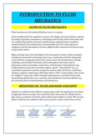
A fluid is a substance that deforms continuously under the application of a shear
(tangential) stress no matter how small the shear stress may be. Fluids tend to
flow when we interact with them while solids tend to deform or bend. We can also
define a fluid as any substance that cannot sustain a shear stress when at rest.
- 4. Velocity Field
Velocity is a vector quantity. The velocity vector can be written in terms of its
three scalar components.
The velocity vector, V indicates the velocity of a fluid particle that is passing
through the point x, y, z at time instant t, in the Eulerian sense. The point x, y, z
is not the ongoing position of an individual particle, but a point we choose to look
at. Hence x, y, and z are independent variables.
The term uniform flow field (as opposed to
uniform flow at a cross section) is used to
describe a flow in which the velocity is
constant, i.e., independent of all space
coordinates, throughout the entire flow field.
In a flow that is uniform at a given cross section, the velocity is constant across
any section normal to the flow, the velocity field is a function of x alone, and thus
the flow model is onedimensional
Steady flowIf properties at every point in a flow field do not change with time,
the flow is termed steady
Timelines, Pathlines, Streaklines, And Streamlines
If a number of adjacent fluid particles in a flow field are marked at a given
instant, they form a line in the fluid at that instant; this line is called a timeline.
Timelines were introduced to demonstrate the deformation of a fluid at successive
instants. Timelines are created by marking a line in a flow and watching how it
evolves over time.
A pathline is the path or trajectory traced out by a moving fluid particle. They
show, over time, the paths individual particles take.
If we focus our attention on a fixed location in space and identify, by the use of
dye or smoke, all fluid particles passing through this point. After a short period of
time we would have a number of identifiable fluid particles in the flow, all of
- 5. which had, at some time, passed through one fixed location in space. The line
joining these fluid particles is defined as a streakline. A streakline is the line
produced in a flow when all particles moving through a fixed point are marked in
some way (e.g., using smoke).
Streamlines are lines drawn in the flow field so that at a given instant they are
tangent to the direction of flow at every point in the flow field. Since the
streamlines are tangent to the velocity vector at every point in the flow field, there
can be no flow across a streamline.
In steady flow, the velocity at each point in the flow field remains constant with
time and, consequently, the streamline shapes do not vary from one instant to the
next. This implies that a particle located on a given streamline will always move
along the same streamline. Furthermore, consecutive particles passing through a
fixed point in space will be on the same streamline and, subsequently, will remain
on this streamline. Thus in a steady flow, pathlines, streaklines, and streamlines
are identical lines in the flow field. For unsteady flow, streaklines, streamlines,
and pathlines will in general have differing shapes.
Stress Field
Each fluid particle can experience: surface forces (pressure, friction) that are
generated by contact with other particles or a solid surface; and body forces (such
as gravity and electromagnetic) that are experienced throughout the particle.
Surface forces on a fluid particle lead to stresses. The concept of stress is useful
for describing how forces acting on the boundaries of a medium (fluid or solid)
are transmitted throughout the medium. When a body moves through a fluid,
stresses are developed within the fluid. The difference between a fluid and a solid
is that stresses in a fluid are mostly generated by motion rather than by
deflection.
- 10. FLUID FLOW
Viscous And Inviscid Flows
Consider a ball flying
through the air, the
ball will experiences
the aerodynamic drag
of the air .What is the
nature of the drag force
of the air on the ball?
Maybe it’s due to friction of the air as it flows over the ball but air has such a low
viscosity, friction might not contribute much to the drag, and the drag might be
due to the pressure buildup in front of the ball as it pushes the air out of the way.
We can predict ahead of time the relative importance of the viscous force, and
force due to the pressure buildup in front of the ball, we can estimate whether or
not viscous forces, as opposed to pressure forces, are negligible by simply
computing the Reynolds number.
Here ρ and μ are the fluid density and viscosity,
respectively, and V and L are the typical or
“characteristic” velocity and size scale of the flow
(in this example the ball velocity and diameter).
If the Reynolds number is “large,” viscous effects will be negligible (but will still
have important consequences), if the Reynolds number is small, viscous effects
will be dominant, if the Reynolds number is neither large nor small, no general
conclusions can be drawn.
- 11. In inviscid flow the streamlines are symmetric fronttoback. Because the mass
flow between any two streamlines is constant, wherever streamlines open up, the
velocity must decrease, and vice versa. Hence we can see that the velocity in the
vicinity of points A and C must be relatively low; at point B it will be high. In
fact, the air comes to rest at points A and C they are stagnation points.
The pressure in this flow is high wherever the velocity is low, and vice versa
hence, points A and C have relatively large (and equal) pressures; point B will be
a point of low pressure. In fact, the pressure distribution on the sphere is
symmetric fronttoback, and there is no net drag force due to pressure. Because
we’re assuming inviscid flow, there can be no drag due to friction either. Hence we
have d’Alembert’s paradox of 1752: The ball experiences no drag!
The noslip condition requires that the velocity everywhere on the surface of the
sphere be zero (in sphere coordinates), but inviscid theory states that it’s high at
point B. Prandtl suggested that even though friction is negligible in general for
high Reynolds number flows, there will always be a
thin boundary layer, in which friction is significant
and across the width of which the velocity increases
rapidly from zero (at the surface) to the value
inviscid flow theory predicts (on the outer edge of the
boundary layer) this boundary layer has another
important consequence: It often leads to bodies
having a wake, as shown in Fig from point D onwards. Point D is a separation
point, where fluid particles are pushed off the object and cause a wake to develop.
Consider once again the original inviscid flow. As a particle moves along the
surface from point B to C, it moves from low to high pressure. This adverse
pressure gradient (a pressure change opposing fluid motion) causes the particles
to slow down as they move along the rear of the sphere. If we now add to this the
fact that the particles are moving in a boundary layer with friction that also
slows down the fluid, the particles will eventually be brought to rest and then
pushed off the sphere by the following particles, forming the wake. This is
generally very bad news: It turns out that the wake will always be relatively low
pressure, but the front of the sphere will still have relatively high pressure. Hence,
the sphere will now have a quite large pressure drag (or form drag—so called
because it’s due to the shape of the object)
It’s interesting to note that although the boundary layer is necessary to explain
the drag on the sphere, the drag is actually due mostly to the asymmetric pressure
distribution created by the boundary layer separation drag directly due to friction
is still negligible!
- 12. How Streamlining Of A Body Works?
The drag force in most aerodynamics is due to the lowpressure wake: If we can
reduce or eliminate the wake, drag will be greatly reduced.
Consider once again why the
separation occurred. Boundary
layer friction slowed down the
particles, but so did the adverse
pressure gradient. The pressure
increased very rapidly across the
back half of the sphere in because
the streamlines opened up so
rapidly. If we make the sphere
teardrop shaped, the streamlines will open up gradually, and hence the pressure
will increase slowly, to such an extent that fluid particles are not forced to
separate from the object until they almost reach the end of the object, as shown.
The wake is much smaller (and it turns out the pressure will not be as low as
before), leading to much less pressure drag. The only negative aspect of this
streamlining is that the total surface area on which friction occurs is larger, so
drag due to friction will increase a little.
Laminar And Turbulent Flows
Consider water flowing out of pipe. At a very low flow rate the water will flow
very smoothly—almost “glasslike.” If we increase the flow rate, the water will
flow in a churnedup, chaotic manner. These are examples of how a viscous flow
can be laminar or turbulent, respectively.
A laminar flow is one in which the fluid particles move in smooth layers, or
laminas; a turbulent flow is one in which the fluid particles rapidly mix as they
move along due to random three dimensional velocity fluctuations.
- 13. In a onedimensional laminar flow, the shear stress is related to the velocity
gradient by the simple relation. For a turbulent flow in which the mean velocity
field is onedimensional, no such simple relation is valid. Random
3d velocity fluctuations (u', v', and w') transport momentum across the mean
flow streamlines, increasing the effective shear stress.
Compressible And Incompressible Flows
Flows in which variations in density are negligible are termed incompressible;
when density variations within a flow are not negligible, the flow is called
compressible. The most common example of compressible flow concerns the flow of
gases, while the flow of liquids may frequently be treated as incompressible.
For many liquids, density is only a weak function of temperature. At modest
pressures, liquids may be considered incompressible. However, at high pressures
compressibility effects in liquids can be important. Pressure and density changes
in liquids are related by the bulk compressibility modulus, or modulus of
elasticity
If the bulk modulus is independent of temperature, then density is only a function
of pressure the fluid is barotropic.
Water hammer and cavitation are examples of the importance of compressibility
effects in liquid flows.
Water hammer is caused by acoustic waves propagating and reflecting in a
confined liquid, for example, when a valve is closed abruptly. The resulting noise
can be similar to “hammering” on the pipes, hence the term.
Cavitation occurs when vapor pockets form in a liquid flow because of local
reductions in pressure (for example at the tip of a boat’s propeller blades).
Depending on the number and distribution of particles in the liquid to which very
small pockets of undissolved gas or air may attach, the local pressure at the onset
of cavitation may be at or below the vapor pressure of the liquid. These particles
act as nucleation sites to initiate vaporization. Vapor pressure of a liquid is the
partial pressure of the vapor in contact with the saturated liquid at a given
temperature. When pressure in a liquid is reduced to less than the vapor pressure,
the liquid may change phase suddenly and “flash” to vapor. The vapor pockets in
a liquid flow may alter the geometry of the flow field substantially. When
adjacent to a surface, the growth and collapse of vapor bubbles can cause serious
- 14. damage by eroding the surface material. Very pure liquids can sustain large
negative pressures—as much as 260 atmospheres for distilled water—before the
liquid “ruptures” and vaporization occurs. Undissolved air is invariably present
near the free surface of water or seawater, so cavitation occurs where the local
total pressure is quite close to the vapor pressure.
The ratio of the flow speed, V, to the local speed of sound, c, in the gas is defined
as the Mach number,
For M <0.3, the maximum density variation is less than 5 percent. Gas flows with
M < 0.3 can be treated as incompressible; a value of M = 0.3 in air at standard
conditions corresponds to a speed of approximately 100 m/s.
Internal And External Flows
Flows completely bounded by solid surfaces are called internal or duct flows.
Flows over bodies immersed in an unbounded fluid are termed external flows.
Both internal and external flows may be laminar or turbulent, compressible or
incompressible.
Flow will generally be laminar for Re <2300 and turbulent for larger values:
Flow in a pipe of constant diameter will be entirely laminar or entirely turbulent,
depending on the value of the velocity V.
The internal flow of liquids in which the duct does not flow full—where there is a
free surface subject to a constant pressure—is termed openchannel flow. Common
examples of openchannel flow include flow in rivers, irrigation ditches, and
aqueducts.
Supersonic flows (M > 1) will behave very differently than subsonic flows (M < 1).
For example, supersonic flows can experience oblique and normal shocks, and can
also behave in a counterintuitive way—e.g., a supersonic nozzle (a device to
accelerate a flow) must be divergent (i.e., it has increasing crosssectional area) in
the direction of flow! We note here also that in a subsonic nozzle (which has a
convergent crosssectional area), the pressure of the flow at the exit plane will
always be the ambient pressure; for a sonic flow, the exit pressure can be higher
than ambient; and for a supersonic flow the exit pressure can be greater than,
equal to, or less than the ambient pressure!