SlideShare a Scribd company logo
1 of 7
Download to read offline
EHD as Sensor Fabrication Technology for Robotic Skins
Jeongsik Shin *a
, Woo Ho Leeb
, Caleb P. Nothnaglea
, Muthu B.J. Wijesundaraa
a
University of Texas at Arlington Research Institute, 7300 Jack Newell Blvd., S., Fort Worth, TX,
USA 76118; b
NGS Lab., Dept. of Electrical Engineering, University of Texas at Arlington,
Arlington, TX, USA 76010
ABSTRACT
Human-robot interaction can be made more sophisticated and intuitive if the entire body of a robot is covered with multi-
modal sensors embedded in artificial skin. In order to efficiently interact with humans in unstructured environments,
robotic skin may require sensors such as touch, impact, and proximity. Integration of various types of sensors into
robotic skin is challenging due to the topographical nature of skin. Printing is a promising technology that can be
explored for sensor integration as it may allow both sensors and interconnects to be directly printed into the skin. We are
developing Electrohydrodynamic (EHD) inkjet printing technology in order to co-fabricate various devices onto a single
substrate. Using strong applied electrostatic forces, EHD allows the printing of microscale features from a wide array of
materials with viscosities ranging from 100 to 1000cP, highly beneficial for multilateral integration. Thus far we have
demonstrated EHD’s capability at printing patterns of Poly(2,3-dihydrothieno-1,4-dioxin)-poly(styrenesulfonate) for
pressure sensor applications, generating patterns with modified commercial photoresist for mask-less lithography, and
obtaining ZnO microstructures for direct device printing. Printed geometries range from a few tens of microns to
millimeters. We have used inks with viscosities ranging from 230 to 520cp and from non-conductive to 135µS/cm.
These results clearly show that the EHD is a promising multi-material printing platform and would be an enabling
technology that can be used to co-fabricate various devices into robotic skin.
Keywords: Robot, skin, tactile sensor, Electrohydrodynamic, inkjet, printing
1. INTRODUCTION
1.1 Robotic Skin Sensors and Applications
Many robotic platforms are expected to co-exist in the same spaces as humans and perform similar physical assignments.
This human-robot co-existence can be successful and safe by developing more sophisticated and intuitive human-robot
interaction capabilities. It is widely accepted that if the entire body of a robot is covered with multi-modal sensors
embedded in artificial skin for real time feedback, the robot will have the capability to successfully interact with real-
world objects and work with humans in unstructured environments. Sensors that enable these sophisticated robotic skins
include touch, impact, temperature, and proximity; however, the integration of various types of sensors into robotic skin
is challenging due to different sensing modalities, the types of materials that robotic skin and sensors are made of, and
the topographical nature of skin.
Much research and developments has been focused on implementing a flexible “sensitive skin” that is composed of an
array of multi-modal sensors and electronics. A modular integration approach is proposed by Schmitz et al. who
developed a robotic skin called ROBOSKIN which is composed of triangular modules each with 12 capacitive sensors
on flexible PCB1
. Mittendorfer et al. developed a hexagonal multimodal sensor module called HEX-O-SKIN which
comprises of hexagonal PCB equipped with discrete temperature, acceleration and proximity sensors for emulating the
human sense of temperature, vibration and touch2
. Both ROBOSKIN and HEX-O-SKIN have been applied to some parts
of commercially available robotic platforms (i.e. iCUB, Nao, and KASPAR) to demonstrate their viability. Though
attractive the integration of these modular sensors into all or part of a robotic skin system is a complex task due to
interconnects and topographical issues.
Most current sensor fabrication and integration relies on semiconductor manufacturing methods and equipment. In most
cases, these conventional fabrication methods are not suited for realizing sensor arrays on large area substrates like
robotics skins. Also conventional manufacturing techniques have limitations on fabricating sensors on flexible and
uneven substrates. Printing is considered to be a promising technology that can be explored for sensor integration onto
large areas substrates. Printing can accommodate an array of materials and substrates with various sizes, shapes, and
Next-Generation Robots and Systems, edited by Dan O. Popa, Muthu B. J. Wijesundara, Proc. of SPIE
Vol. 9116, 91160F · © 2014 SPIE · CCC code: 0277-786X/14/$18 · doi: 10.1117/12.2053429
Proc. of SPIE Vol. 9116 91160F-1
Downloaded From: http://proceedings.spiedigitallibrary.org/ on 08/19/2014 Terms of Use: http://spiedl.org/terms
Pressure
High voltage
Ink chamber
and nozzle
Sample
X,Y Programmable Stage
(a)
F Nozzle
T
Liquid meniscus
(b)
Pirc._+- Ink jetting
Jet diameter
Nozzle diameter
complex topographies. Among many printing techniques, inkjet printing can be used at various stages of micro/nano
systems manufacturing; for instance, direct device printing (gas sensors, organic LEDs, and thin film transistors), mask-
less lithography (front-end fabrication as well as PCB production for back-end applications), and packaging (dispensing
epoxies and printing interconnects). The ability to integrate several disparate materials into one fabrication platform is a
key for multi-modal sensor fabrication on robotic skin. It is also drawing attention due to its cost effectiveness as
printing sensors does not require a large amount of ink materials and does not generate waste.
In this paper, we explore Electrohydrodynamic (EHD) printing as a versatile printing method that can be used for sensor
integration onto robotic skin. The main benefit in using our EHD printing for sensor fabrication is its flexibility in
printing various liquids and metals onto conductive and even potentially nonconductive substrates of differing
topographies. As robotic skin would require a fusion of materials, a system with the capability to dispense nearly any
material with minimal reworking is very advantageous. We will discuss here the printability of disparate materials
(conductive, non-conductive, and colloidal) with experimental results. We will also highlight the applicability of these
materials for sensor integration onto robotic skins.
1.2 Electrohydrodynamic Printing (EHD)
EHD printing uses an electric field to eject fluids. The applied electric field enables fine jetting which creates smaller
features by an order of magnitude below the nozzle size3
. In EHD, a pressure is applied to the ink chamber until a fluid
meniscus is formed at the end the nozzle tip before applying an electric field across the nozzle and substrate for jetting.
Figure 1(a) shows a generic configuration of a typical EHD setup. The fine jetting feature is possible due to the pulling
and focusing effect from the electric field, in comparison to pushing through applied pressure as in the case in piezo-
driven jetting. Electric field-driven ejection enables creating smaller features by an order of magnitude below the nozzle
size thereby vastly improving the resolution as shown in Figure 1(b) and (c). Applying a DC electric field produces
stable and continuous jetting which is suitable for printing uniform lines4,5
. Drop-on-demand printing can be achieved by
using external pulsating voltage. This mode is very useful in printing complicated patterns such as those required for
sensor fabrication. Micro-dripping is another jetting mode that uses pulsating voltage to deliver droplets to a substrate
without a spreading effect. It has been demonstrated by making uniform patterns out of micro/nano sized droplets and
would be highly beneficial for fabrication of a sensor array with minimal sensor to sensor variation 6
.
Figure 1. (a) Generic printer configuration of EHD printing. (b) Nozzle tip with fluid meniscus before applying electric
field, and (c) jetting characteristics after applying electric field.
One advantage of using strong electric fields for fluid ejection is the ability to print materials with viscosities as high as
1000cP. This expands the choice of available materials and is highly beneficial for the fabrication of various types of
sensors. In comparison piezo-jet based printing can only handle inks with viscosities of up to 50cP. The printability of
high viscosity materials enables the printing of thicker microstructures; a key feature that sets EHD apart from other
inkjet printing methods which typically use multiple superimposed print runs to achieve this. Despite these apparent key
advantages, one of the drawbacks of EHD is the requirement of a conductive substrate surface for generating an
electrical potential. The requirement of a conductive substrate can be eliminated by using a ring electrode for electric
field generation, which is an active research area for EHD printing.
Proc. of SPIE Vol. 9116 91160F-2
Downloaded From: http://proceedings.spiedigitallibrary.org/ on 08/19/2014 Terms of Use: http://spiedl.org/terms
Camera
Tube to supply
pneumatic
pressure
Ink chamber
Mirror
Substrate
Nozzle
2. EXPERIMENTAL
2.1 EHD Setup
The EHD system used in this experiment consists of an ink chamber, interchangeable nozzle tips, a high-voltage power
supply, a function generator, a precision pressure regulator, and an automated positioning stage. Figure 2 shows the
current configuration of the EHD set up used in this work. A high DC voltage is maintained between the nozzle tip and
the substrate to create continuous jetting while a pulsating voltage generated through a function generator is used for
drop-on-demand printing. Voltage settings applied in the experiments vary for different inks. The distance between the
nozzle tip and substrate varies based on the size of the nozzle tip and the voltage applied. The use of precision staging
includes four degrees of freedom (X, Y, Z, and Theta) allowing the system to scan non-planer surfaces with micron
precision and maintain a constant distance between nozzle and substrate for EHD printing.
Figure 2. The current configuration of the EHD setup (a) CAD model showing gantry system with x-y-z-theta stages (b) A
photograph of the current EHD setup (high voltage amplifier, function generator and precision pressure regulator are not
shown in this photograph)
2.2 Printing Experiments
Three different types of custom inks with different characteristics were used. The first type of ink was used to
demonstrate the mask-less lithography capability of EHD. Commercial KMPR 1010 photoresist7
, a non-conductive
polymeric solution, was modified using N-Methylpyrrolidone (NMP) and OMNOVA PolyFox Fluorosurfactants to
achieve the desired properties for printing. The measured viscosity of the modified KMPR 1010 was 520cP. Gold coated
silicon, silicon oxide, and Kapton were used as substrates. Drop-on demand experiments were performed with a square
wave of 600Hz with a 20% duty cycle. The peak of the square wave was 600V with a bias of 400V. A gold coated 10µm
glass nozzle was used with a gap of 160µm between the nozzle and the substrate. After printing gold was selectively
etched and KMPR was removed from the substrate to form patterned gold traces.
The second type of ink made of PEDOT:PSS, Poly(2,3-dihydrothieno-1,4-dioxin)-poly(styrenesulfonate), a widely used
pressure sensor fabrication material was tested for the development of an EHD printed sensor fabrication process. This
test used 5.0 wt. % conductive screen printable paste from Orgacon™ EL-P-5015, PEDOT:PSS, with a resistance and
viscosity of 50-150Ω/sq and 50,000-90,000cP, respectively. The material was diluted with NMP to reduce the viscosity
and the initial experiments were performed using the ink with viscosity at 230cP. A 100µm stainless steel nozzle was
used and a DC voltage of 1.6kV with an 800 µm gap between the nozzle and the substrate were used during printing.
The last set of experiments were performed using highly conductive zinc ion (Zn2+) ink to demonstrate the EHD
capability of direct device printing. The viscosity of the ink was 455cP, made using zinc acetate (precursor), ethylene
glycol (solvent), and polyvinylpyrrolidone (binding matrix). A continuous jetting mode with a DC voltage of 850V was
used. A gold coated 10 µm glass nozzle was used with printing speeds (substrate travel) of 600, 1000, 1400, and 1800
mm/min. Printing was followed by a soft bake step (100ºC for one minute) to evaporate the solvents. Finally, a sintering
process was performed above 400ºC for transforming printed structures into polycrystalline Zinc Oxide (ZnO). .
Proc. of SPIE Vol. 9116 91160F-3
Downloaded From: http://proceedings.spiedigitallibrary.org/ on 08/19/2014 Terms of Use: http://spiedl.org/terms
40 -
r 35
-a
d 30
::-1 25
20 -
300 400 500 600 700 800
Printing Speed mm /min
E
E
O
O
N
E
E
O
O
E
E
OO00
[L(lr/!
®®®©®®©VA.i`C/e(<(l(((CL((E(
ED®OO(.(;(c0C-(((c(((((((
EpOOOOO®C,C((((((((((((C(
OO
OO©©OQCC((((((((((
3. RESULTS AND DISCUSSION
3.1 Mask-less lithography
The objective of using mask-less lithography for patterning metal traces on various substrates is to demonstrate the
feasibility of EHD printing as a pattern transfer technique that is well suited for sensor integration onto robotic skin.
Figure 3 shows printed KMPR patterns on gold coated silicon substrates. Modified KMPR was used as an EHD ink
because it was designed for a similar kind of lithographic processes. Drop-on-demand printing was performed at a
frequency of 600Hz with substrate speeds changing from 200 to 1000 mm/min. Data shows that the transition from dots
to uniform lines occurs around a 600 mm/min stage speed. Further reducing the stage speed, the linewidth was increased.
The linewidth as a function of stage speed is shown in figure 4. These particular printing conditions resulted in a line
with a maximum height of 3 microns with a parabolic cross sectional shape. The parabolic line shape was expected due
to surface tension driven restructuring. The process has been repeated on gold coated silicon oxide and Kapton substrates
(data not shown) with similar results
Figure 3. Variation of line shapes with respect to speeds for 600Hz drop-on demand KMPR printing. Printing speed was
changed from 1000mm/min to 200mm/min while other conditions remained the same.
Figure 4. The linewidth variation as a function of stage speed for drop-on demand KMPR printing at 600Hz.
The viability of pattern transfer using EHD printed lines was evaluated using typical etching and resist removal
processes. Figure 5 displays images of patterned gold lines on (a) silicon, (b) silicon oxide, and (c) Kapton clearly
showing pattern transferability on various substrate materials. Most robotic skins are fabricated using flexible substrates
Proc. of SPIE Vol. 9116 91160F-4
Downloaded From: http://proceedings.spiedigitallibrary.org/ on 08/19/2014 Terms of Use: http://spiedl.org/terms
(a) (b) 150µm
A
2220µm
< >
` 2160 µm
of a size, shape, and topography that are not suited for conventional lithography. This data encourages replacing
photolithography processes with direct EHD printing of photoresist for mask-less lithography-based patterning of metal
interconnects and other materials for sensor integration onto robotic skin
Figure 5. EHD-based mask-less lithography patterned gold lines on (a) silicon (linewidth 23.5μm), (b) silicon oxide (linewidth
31.3μm) and (c) Kapton (linewidth 16.8μm).
3.2 Printing PEDOT:PSS Sensing Layers
In recent years, PEDOT:PSS has been the sensing material used in touch screen technology. PEDOT:PSS is a
transparent, conjugated conducting polymer that is highly ductile and stretchable along with having good environmental
stability. Several researchers have fabricated and characterized tactile sensors using PEDOT:PSS8,9,10,11
. The resistance
of ink-jet printed PEDOT:PSS is about a few kilo ohms. It has elongation of 10% or more. The gauge factor of
PEDOT:PSS is 5 to 20, whereas the gauge factor of a conventional metal film is 2. Calvert et al. fabricated piezoresistive
sensors using PEDOT:PSS inkjet printing for smart textiles8
. That tactile sensor showed a resistance of 5 kilo Ohms and
a gauge factor of 5 after 500 cycles of testing. Here we report the results of a first attempt at printing PEDOT:PSS in
order to fabricate pressure and strain sensors as well as interconnects on robotic skin. Figure 6 shows the printing results
for an array of interconnected square pads printed on a gold coated glass substrate. By examining the results as printed, it
is apparent that solvent pooling and surface tension-driven restructuring are occurring. Currently, optimization of the
PEDOT:PSS ink and printing process is progressing to mitigate this issue. Future plans include characterization of the
printed material and implementation of the printing process to tactile sensor fabrication on skin like substrates.
Figure 6. The results of an array of interconnected square pads printed on gold coated glass substrate (a) as printed and (b)
after room temperature drying for three hours.
3.3 Printing Metal Oxide Microstructures
As multifunctional materials, metal oxides are poised to play a critical role in many advanced technologies that include
flat panel displays, printed electronics, sensors, and actuators. Although printing and fabrication methods described here
may not lead to fabrication of these devices directly onto robotic skin due a high temperature processing step, EHD
Proc. of SPIE Vol. 9116 91160F-5
Downloaded From: http://proceedings.spiedigitallibrary.org/ on 08/19/2014 Terms of Use: http://spiedl.org/terms
et A's
60
c0
50
v 40
3
c 30
I
600
500
£400
w /-Before Sintering
300 -After Sintering
u 200 at 400QC
:c100
400 800 1200 1600 2000
Priting Speed mm /min.
o
450 470 490 510
Lateral Distance(pm)
450
doo (a)
350
r g
é
250
e 200 ZnO (100]
¡ISO
)
ó 100
4)
o+wwrn,rwr
26
2,10 (0021
ZnO (1011
i
two) ''41'414I.4444440"
30 32 34 36 38 40
2 -Tnela Scat!
(b)
printing can be used to integrate metal oxide-based miniature gas sensors, thin film transistors, and energy harvesters to
other parts of a robotic platform. This investigation was focused on printing ZnO from a highly conductive (135µS/cm)
zinc ion containing ink. The printing results discussed in this section not only demonstrate the formation of ZnO
microstructures but also show the capability of EHD as a versatile printing method by printing non-conductive KMPR
ink to highly conductive Zinc ion containing ink.
After printing on a silicon oxide substrate, printed microstructures were subjected to a sintering process for creating ZnO
microstructures. X-Ray Diffraction (XRD) analysis performed on the printed ZnO films sintered at various temperatures
confirmed that the ink produces polycrystalline ZnO upon heating above 400ºC. Figure 7(a) displays the representative
XRD data showing the polycrystalline nature of the sintered film. Figure 7(b) shows the SEM image of formed ZnO
lines with no detectable cracks or pinholes. Further investigation is needed to better understand the effect of matrix
loading and sintering on grain characteristics and film stress.
Figure 7. (a) the representative XRD data of the sintered ZnO film at 400ºC and (b) the SEM image of ZnO microstructure.
Figure 8 (a) shows the linewidth of the printed structures based on printing speed using at an jetting voltage of 850V.
After the sintering process, one of the key aspects to note is the shrinkage of the structure due to the removal of matrix
materials. It is therefore essential to build a correlation between printed and final microstructure geometry in order to
obtain desired device geometry. Figure 8 (b) shows the representative surface profile of ZnO ink printed at 850V with a
printing speed of 1000 mm/min before and after sintering. The lateral and thickness shrinkage percentage for this
particular ink were determined to be 3% and 92% respectively. With the negligible lateral shrinkage, this printing has
resulted in ZnO microstructures with linewidths ranging from 18 to 65µm and thicknesses ranging from 33 to 62nm. The
capability of printing a wide range of thickness by changing process parameters is encouraging as this can lead to
different types of device using EHD.
Figure 8. (a) Linewidth of printed structures as a function of printing speed using a jetting voltage of 850V and (b) surface
profile data on ZnO ink printed at 850V with a printing speed of 1000 mm/min before and after sintering.
4. CONCLUSIONS AND FUTURE DIRECTIONS
Based on the preliminary experimental work performed here, it is evident that EHD printing could be an attractive
method for integrating sensors into robotic skins for human-robot interactions. We have shown the printing of high
Proc. of SPIE Vol. 9116 91160F-6
Downloaded From: http://proceedings.spiedigitallibrary.org/ on 08/19/2014 Terms of Use: http://spiedl.org/terms
viscosity materials with varying conductivity and the ability to achieve geometries ranging from a few tens of microns to
millimeters. This clearly shows that the EHD is an enabling technology that can be used to co-fabricate various devices
onto a single substrate. Although many technological advancements are necessary to fully tap the potential of EHD, the
experimental results discussed here evidently show the possibility of EHD as a manufacturing platform for integrating
sensors into robotic skin.
Our immediate future research is focused on two main areas: (1) further development of the EHD printer technology,
and (2) fabricating an array of pressure sensors onto flexible substrates by printing PEDOT:PSS. The primary goal of
EHD technology development is to integrate a ring electrode to the nozzle head so that printing can be performed
regardless of substrate conductivity. Though several attempts have been made by a few research groups to integrate ring
electrodes into EHD printers, this is a major technological barrier that hampers the application of EHD printing
technology to a wide array of substrates. In terms of sensors for robotic skins, we plan to fabricate an array of pressure
sensors onto a flexible substrate by using EHD printing. The work will starts with characterization of printed materials
and ends with the fabrication of an entire sensor array by printing PEDOT:PSS and interconnects using EHD.
5. ACKNOWLEDGMENTS
This work was supported in part by the Office of Naval Research Grants #N00014-08-C-0390, #N00014-11-C-0391, and
the National Science Foundation NRI Grant #IIS-1208623. We wish to thank Raminderdeep Sidhu, Lester Corwin, and
the UTA Research Institute staff for their help with the experimental work presented in this paper.
REFERENCES
[1] Schmitz, A., Maiolino, P., Maggiali, M., Natale, L., Cannata, G., and Metta, G., “Methods and Technologies for the
Implementation of Large-Scale Robot Tactile Sensors,” IEEE Trans. on Robotics, Vol. 27, No. 3, pp. 389-400, June
2011.
[2] Mittendorfer, P. and Cheng, G., “Humanoid Multi-Modal Tactile Sensing Modules,” IEEE Trans. on Robotics, Vol.
27, No. 3, pp. 401-410, June 2011.
[3] Chen, C.-H., Saville, D. A., and Aksay, I. A., “Scaling laws for pulsed electrohydrodynamic drop formation,”
Applied Physics Letters 89, 12410, 2006.
[4] Lee, D.-Y., Lee, J.-C., Shin, Y.-S., Park, S.-E., Yu, T.-U., Kim, Y.-J. and Hwang, J., “Structuring of conductive
silver line by electrohydrodynamic jet printing and its electrical characterization,” Journal of Physics: Conference
Series 142, 012039, 2008.
[5] Sidhu, R., Sin, J., Lee, W. H., Stephanou, H. E., and Wijesundara, M.B.J., “Electrohydrodynamic printing of metal
oxide microstructures,” International Conference On Micromanufacturing, pp. 458-461, 2012
[6] Choi, J., Kim, Y.-J., Son, S. U., An, K. C., and Lee, S., “The investigation of electrostatic induced inkjet printing
system,” Nanotech, pp. 464-467, 2010.
[7] http://www.microchem.com/pdf/KMPRDataSheetver4_2a.htm
[8] Calvert, P., Patra, P., Lo, T-C., Chen, C., Sawhney, A., and Agrawal, A., “Piezoresistive sensors for smart textiles,”
Proc. SPIE 6524, Electroactive Polymer Actuators and Devices, 2007.
[9] Latessa, G., Brunetti, F., Reale, A., Saggio, G., and Carlo, A. D., “Piezoresistive behavior of flexible PEDOT:PSS
based sensors,” Sensors and Actuators B: Chemical, Vol. 139, Issue 2, pp. 304-309, June 2009.
[10]Lang, U., Rust, P., and Dual, J., “Towards fully polymeric MEMS: Fabrication and testing of PEDOT/PSS strain
gauges,” Proc. Micro- and Nano-Engineering, pp. 1050-1053, MNE 2007.
[11]Takamatsu, S. and Itoh, T., “Novel MEMS Devices Based on Conductive Polymers,” Electrochemical Society,
Interface, 2012.
Proc. of SPIE Vol. 9116 91160F-7
Downloaded From: http://proceedings.spiedigitallibrary.org/ on 08/19/2014 Terms of Use: http://spiedl.org/terms

More Related Content

Similar to EHD as Sensor Fabrication Technology for Robotic Skins

Inkjet printed graphene-based flexible humidity sensor for environmental appl...
Inkjet printed graphene-based flexible humidity sensor for environmental appl...Inkjet printed graphene-based flexible humidity sensor for environmental appl...
Inkjet printed graphene-based flexible humidity sensor for environmental appl...
Conference Papers
 
Foldable World_update
Foldable World_updateFoldable World_update
Robotic Hand in Motion Final Paper
Robotic Hand in Motion Final PaperRobotic Hand in Motion Final Paper
Robotic Hand in Motion Final Paper
Lauren Wellons
 
Touché Enhancing Touch Interaction on Humans, Screens, Liqu.docx
Touché Enhancing Touch Interaction on Humans, Screens, Liqu.docxTouché Enhancing Touch Interaction on Humans, Screens, Liqu.docx
Touché Enhancing Touch Interaction on Humans, Screens, Liqu.docx
edwardmarivel
 

Similar to EHD as Sensor Fabrication Technology for Robotic Skins (20)

Implementation of capacitive touch screen in smart devices
Implementation of capacitive touch screen in smart devicesImplementation of capacitive touch screen in smart devices
Implementation of capacitive touch screen in smart devices
 
Electronic Skin for Programmable Touch Operation Platform
Electronic Skin for Programmable Touch Operation PlatformElectronic Skin for Programmable Touch Operation Platform
Electronic Skin for Programmable Touch Operation Platform
 
Electronic skin
Electronic skinElectronic skin
Electronic skin
 
Touch screen-technology-1
Touch screen-technology-1Touch screen-technology-1
Touch screen-technology-1
 
A touchscreen
A touchscreen A touchscreen
A touchscreen
 
Neuralink white-paper. Elon Musk & Neuralink
Neuralink white-paper. Elon Musk & NeuralinkNeuralink white-paper. Elon Musk & Neuralink
Neuralink white-paper. Elon Musk & Neuralink
 
Inkjet printed graphene-based flexible humidity sensor for environmental appl...
Inkjet printed graphene-based flexible humidity sensor for environmental appl...Inkjet printed graphene-based flexible humidity sensor for environmental appl...
Inkjet printed graphene-based flexible humidity sensor for environmental appl...
 
Eurosensors_Anton
Eurosensors_AntonEurosensors_Anton
Eurosensors_Anton
 
A SURVEY ON NUMEROUS DEVELOPMENTS IN MULTI-TOUCH TECHNOLOGY
A SURVEY ON NUMEROUS DEVELOPMENTS IN MULTI-TOUCH TECHNOLOGYA SURVEY ON NUMEROUS DEVELOPMENTS IN MULTI-TOUCH TECHNOLOGY
A SURVEY ON NUMEROUS DEVELOPMENTS IN MULTI-TOUCH TECHNOLOGY
 
Foldable World_update
Foldable World_updateFoldable World_update
Foldable World_update
 
IRJET- Printed Conductive Transparent Films for the Fabrication of Sensors by...
IRJET- Printed Conductive Transparent Films for the Fabrication of Sensors by...IRJET- Printed Conductive Transparent Films for the Fabrication of Sensors by...
IRJET- Printed Conductive Transparent Films for the Fabrication of Sensors by...
 
Print screen
Print screenPrint screen
Print screen
 
Robotic Hand in Motion Final Paper
Robotic Hand in Motion Final PaperRobotic Hand in Motion Final Paper
Robotic Hand in Motion Final Paper
 
Flexible electronics paper
Flexible electronics paperFlexible electronics paper
Flexible electronics paper
 
Holographic
HolographicHolographic
Holographic
 
Touché Enhancing Touch Interaction on Humans, Screens, Liqu.docx
Touché Enhancing Touch Interaction on Humans, Screens, Liqu.docxTouché Enhancing Touch Interaction on Humans, Screens, Liqu.docx
Touché Enhancing Touch Interaction on Humans, Screens, Liqu.docx
 
Han12
Han12Han12
Han12
 
Haptics
HapticsHaptics
Haptics
 
Touchscreen-MOBILE TECHNOLOGY
Touchscreen-MOBILE TECHNOLOGYTouchscreen-MOBILE TECHNOLOGY
Touchscreen-MOBILE TECHNOLOGY
 
FLEXIBLE ELECTRONIC SKIN
FLEXIBLE ELECTRONIC SKINFLEXIBLE ELECTRONIC SKIN
FLEXIBLE ELECTRONIC SKIN
 

More from Hillary Green

Quasi-Static Evaluation of a Modular and Reconfigurable Manufacturing Cell
Quasi-Static Evaluation of a Modular and Reconfigurable Manufacturing CellQuasi-Static Evaluation of a Modular and Reconfigurable Manufacturing Cell
Quasi-Static Evaluation of a Modular and Reconfigurable Manufacturing Cell
Hillary Green
 
Needs and Emerging Trends of Remote Sensing
Needs and Emerging Trends of Remote SensingNeeds and Emerging Trends of Remote Sensing
Needs and Emerging Trends of Remote Sensing
Hillary Green
 

More from Hillary Green (11)

Passport to the World: An Intervention to Depression
Passport to the World: An Intervention to DepressionPassport to the World: An Intervention to Depression
Passport to the World: An Intervention to Depression
 
Technology and Spinal Cord Injury (SCI): How could technology further help th...
Technology and Spinal Cord Injury (SCI): How could technology further help th...Technology and Spinal Cord Injury (SCI): How could technology further help th...
Technology and Spinal Cord Injury (SCI): How could technology further help th...
 
Novel Microchannel Electrode Array: Towards Bioelectronic Medical Interfacing...
Novel Microchannel Electrode Array: Towards Bioelectronic Medical Interfacing...Novel Microchannel Electrode Array: Towards Bioelectronic Medical Interfacing...
Novel Microchannel Electrode Array: Towards Bioelectronic Medical Interfacing...
 
Quasi-Static Evaluation of a Modular and Reconfigurable Manufacturing Cell
Quasi-Static Evaluation of a Modular and Reconfigurable Manufacturing CellQuasi-Static Evaluation of a Modular and Reconfigurable Manufacturing Cell
Quasi-Static Evaluation of a Modular and Reconfigurable Manufacturing Cell
 
Needs and Emerging Trends of Remote Sensing
Needs and Emerging Trends of Remote SensingNeeds and Emerging Trends of Remote Sensing
Needs and Emerging Trends of Remote Sensing
 
IEEE-RAS Robot Challenges Summary
IEEE-RAS Robot Challenges SummaryIEEE-RAS Robot Challenges Summary
IEEE-RAS Robot Challenges Summary
 
UTARI Smart Homes Foundatin Presentation
UTARI Smart Homes Foundatin PresentationUTARI Smart Homes Foundatin Presentation
UTARI Smart Homes Foundatin Presentation
 
Operation Finally Home Smart Home Presentation
Operation Finally Home Smart Home PresentationOperation Finally Home Smart Home Presentation
Operation Finally Home Smart Home Presentation
 
Gary Sinise Foundation Smart Home Presentation
Gary Sinise Foundation Smart Home PresentationGary Sinise Foundation Smart Home Presentation
Gary Sinise Foundation Smart Home Presentation
 
AUVSI 2014: Beyond the Booth
AUVSI 2014: Beyond the BoothAUVSI 2014: Beyond the Booth
AUVSI 2014: Beyond the Booth
 
Lending a Helping Hand: Exploring the Future of Assistive Robotics - AUVSI 2014
Lending a Helping Hand: Exploring the Future of Assistive Robotics - AUVSI 2014Lending a Helping Hand: Exploring the Future of Assistive Robotics - AUVSI 2014
Lending a Helping Hand: Exploring the Future of Assistive Robotics - AUVSI 2014
 

Recently uploaded

Cloud Frontiers: A Deep Dive into Serverless Spatial Data and FME
Cloud Frontiers:  A Deep Dive into Serverless Spatial Data and FMECloud Frontiers:  A Deep Dive into Serverless Spatial Data and FME
Cloud Frontiers: A Deep Dive into Serverless Spatial Data and FME
Safe Software
 
Architecting Cloud Native Applications
Architecting Cloud Native ApplicationsArchitecting Cloud Native Applications
Architecting Cloud Native Applications
WSO2
 
Cloud Frontiers: A Deep Dive into Serverless Spatial Data and FME
Cloud Frontiers:  A Deep Dive into Serverless Spatial Data and FMECloud Frontiers:  A Deep Dive into Serverless Spatial Data and FME
Cloud Frontiers: A Deep Dive into Serverless Spatial Data and FME
Safe Software
 
+971581248768>> SAFE AND ORIGINAL ABORTION PILLS FOR SALE IN DUBAI AND ABUDHA...
+971581248768>> SAFE AND ORIGINAL ABORTION PILLS FOR SALE IN DUBAI AND ABUDHA...+971581248768>> SAFE AND ORIGINAL ABORTION PILLS FOR SALE IN DUBAI AND ABUDHA...
+971581248768>> SAFE AND ORIGINAL ABORTION PILLS FOR SALE IN DUBAI AND ABUDHA...
?#DUbAI#??##{{(☎️+971_581248768%)**%*]'#abortion pills for sale in dubai@
 

Recently uploaded (20)

MINDCTI Revenue Release Quarter One 2024
MINDCTI Revenue Release Quarter One 2024MINDCTI Revenue Release Quarter One 2024
MINDCTI Revenue Release Quarter One 2024
 
Apidays New York 2024 - The value of a flexible API Management solution for O...
Apidays New York 2024 - The value of a flexible API Management solution for O...Apidays New York 2024 - The value of a flexible API Management solution for O...
Apidays New York 2024 - The value of a flexible API Management solution for O...
 
DBX First Quarter 2024 Investor Presentation
DBX First Quarter 2024 Investor PresentationDBX First Quarter 2024 Investor Presentation
DBX First Quarter 2024 Investor Presentation
 
Exploring Multimodal Embeddings with Milvus
Exploring Multimodal Embeddings with MilvusExploring Multimodal Embeddings with Milvus
Exploring Multimodal Embeddings with Milvus
 
How to Troubleshoot Apps for the Modern Connected Worker
How to Troubleshoot Apps for the Modern Connected WorkerHow to Troubleshoot Apps for the Modern Connected Worker
How to Troubleshoot Apps for the Modern Connected Worker
 
Navigating the Deluge_ Dubai Floods and the Resilience of Dubai International...
Navigating the Deluge_ Dubai Floods and the Resilience of Dubai International...Navigating the Deluge_ Dubai Floods and the Resilience of Dubai International...
Navigating the Deluge_ Dubai Floods and the Resilience of Dubai International...
 
Cloud Frontiers: A Deep Dive into Serverless Spatial Data and FME
Cloud Frontiers:  A Deep Dive into Serverless Spatial Data and FMECloud Frontiers:  A Deep Dive into Serverless Spatial Data and FME
Cloud Frontiers: A Deep Dive into Serverless Spatial Data and FME
 
ProductAnonymous-April2024-WinProductDiscovery-MelissaKlemke
ProductAnonymous-April2024-WinProductDiscovery-MelissaKlemkeProductAnonymous-April2024-WinProductDiscovery-MelissaKlemke
ProductAnonymous-April2024-WinProductDiscovery-MelissaKlemke
 
presentation ICT roal in 21st century education
presentation ICT roal in 21st century educationpresentation ICT roal in 21st century education
presentation ICT roal in 21st century education
 
TrustArc Webinar - Unlock the Power of AI-Driven Data Discovery
TrustArc Webinar - Unlock the Power of AI-Driven Data DiscoveryTrustArc Webinar - Unlock the Power of AI-Driven Data Discovery
TrustArc Webinar - Unlock the Power of AI-Driven Data Discovery
 
Architecting Cloud Native Applications
Architecting Cloud Native ApplicationsArchitecting Cloud Native Applications
Architecting Cloud Native Applications
 
Spring Boot vs Quarkus the ultimate battle - DevoxxUK
Spring Boot vs Quarkus the ultimate battle - DevoxxUKSpring Boot vs Quarkus the ultimate battle - DevoxxUK
Spring Boot vs Quarkus the ultimate battle - DevoxxUK
 
Repurposing LNG terminals for Hydrogen Ammonia: Feasibility and Cost Saving
Repurposing LNG terminals for Hydrogen Ammonia: Feasibility and Cost SavingRepurposing LNG terminals for Hydrogen Ammonia: Feasibility and Cost Saving
Repurposing LNG terminals for Hydrogen Ammonia: Feasibility and Cost Saving
 
Cloud Frontiers: A Deep Dive into Serverless Spatial Data and FME
Cloud Frontiers:  A Deep Dive into Serverless Spatial Data and FMECloud Frontiers:  A Deep Dive into Serverless Spatial Data and FME
Cloud Frontiers: A Deep Dive into Serverless Spatial Data and FME
 
+971581248768>> SAFE AND ORIGINAL ABORTION PILLS FOR SALE IN DUBAI AND ABUDHA...
+971581248768>> SAFE AND ORIGINAL ABORTION PILLS FOR SALE IN DUBAI AND ABUDHA...+971581248768>> SAFE AND ORIGINAL ABORTION PILLS FOR SALE IN DUBAI AND ABUDHA...
+971581248768>> SAFE AND ORIGINAL ABORTION PILLS FOR SALE IN DUBAI AND ABUDHA...
 
FWD Group - Insurer Innovation Award 2024
FWD Group - Insurer Innovation Award 2024FWD Group - Insurer Innovation Award 2024
FWD Group - Insurer Innovation Award 2024
 
2024: Domino Containers - The Next Step. News from the Domino Container commu...
2024: Domino Containers - The Next Step. News from the Domino Container commu...2024: Domino Containers - The Next Step. News from the Domino Container commu...
2024: Domino Containers - The Next Step. News from the Domino Container commu...
 
Strategies for Landing an Oracle DBA Job as a Fresher
Strategies for Landing an Oracle DBA Job as a FresherStrategies for Landing an Oracle DBA Job as a Fresher
Strategies for Landing an Oracle DBA Job as a Fresher
 
Apidays New York 2024 - APIs in 2030: The Risk of Technological Sleepwalk by ...
Apidays New York 2024 - APIs in 2030: The Risk of Technological Sleepwalk by ...Apidays New York 2024 - APIs in 2030: The Risk of Technological Sleepwalk by ...
Apidays New York 2024 - APIs in 2030: The Risk of Technological Sleepwalk by ...
 
AWS Community Day CPH - Three problems of Terraform
AWS Community Day CPH - Three problems of TerraformAWS Community Day CPH - Three problems of Terraform
AWS Community Day CPH - Three problems of Terraform
 

EHD as Sensor Fabrication Technology for Robotic Skins

  • 1. EHD as Sensor Fabrication Technology for Robotic Skins Jeongsik Shin *a , Woo Ho Leeb , Caleb P. Nothnaglea , Muthu B.J. Wijesundaraa a University of Texas at Arlington Research Institute, 7300 Jack Newell Blvd., S., Fort Worth, TX, USA 76118; b NGS Lab., Dept. of Electrical Engineering, University of Texas at Arlington, Arlington, TX, USA 76010 ABSTRACT Human-robot interaction can be made more sophisticated and intuitive if the entire body of a robot is covered with multi- modal sensors embedded in artificial skin. In order to efficiently interact with humans in unstructured environments, robotic skin may require sensors such as touch, impact, and proximity. Integration of various types of sensors into robotic skin is challenging due to the topographical nature of skin. Printing is a promising technology that can be explored for sensor integration as it may allow both sensors and interconnects to be directly printed into the skin. We are developing Electrohydrodynamic (EHD) inkjet printing technology in order to co-fabricate various devices onto a single substrate. Using strong applied electrostatic forces, EHD allows the printing of microscale features from a wide array of materials with viscosities ranging from 100 to 1000cP, highly beneficial for multilateral integration. Thus far we have demonstrated EHD’s capability at printing patterns of Poly(2,3-dihydrothieno-1,4-dioxin)-poly(styrenesulfonate) for pressure sensor applications, generating patterns with modified commercial photoresist for mask-less lithography, and obtaining ZnO microstructures for direct device printing. Printed geometries range from a few tens of microns to millimeters. We have used inks with viscosities ranging from 230 to 520cp and from non-conductive to 135µS/cm. These results clearly show that the EHD is a promising multi-material printing platform and would be an enabling technology that can be used to co-fabricate various devices into robotic skin. Keywords: Robot, skin, tactile sensor, Electrohydrodynamic, inkjet, printing 1. INTRODUCTION 1.1 Robotic Skin Sensors and Applications Many robotic platforms are expected to co-exist in the same spaces as humans and perform similar physical assignments. This human-robot co-existence can be successful and safe by developing more sophisticated and intuitive human-robot interaction capabilities. It is widely accepted that if the entire body of a robot is covered with multi-modal sensors embedded in artificial skin for real time feedback, the robot will have the capability to successfully interact with real- world objects and work with humans in unstructured environments. Sensors that enable these sophisticated robotic skins include touch, impact, temperature, and proximity; however, the integration of various types of sensors into robotic skin is challenging due to different sensing modalities, the types of materials that robotic skin and sensors are made of, and the topographical nature of skin. Much research and developments has been focused on implementing a flexible “sensitive skin” that is composed of an array of multi-modal sensors and electronics. A modular integration approach is proposed by Schmitz et al. who developed a robotic skin called ROBOSKIN which is composed of triangular modules each with 12 capacitive sensors on flexible PCB1 . Mittendorfer et al. developed a hexagonal multimodal sensor module called HEX-O-SKIN which comprises of hexagonal PCB equipped with discrete temperature, acceleration and proximity sensors for emulating the human sense of temperature, vibration and touch2 . Both ROBOSKIN and HEX-O-SKIN have been applied to some parts of commercially available robotic platforms (i.e. iCUB, Nao, and KASPAR) to demonstrate their viability. Though attractive the integration of these modular sensors into all or part of a robotic skin system is a complex task due to interconnects and topographical issues. Most current sensor fabrication and integration relies on semiconductor manufacturing methods and equipment. In most cases, these conventional fabrication methods are not suited for realizing sensor arrays on large area substrates like robotics skins. Also conventional manufacturing techniques have limitations on fabricating sensors on flexible and uneven substrates. Printing is considered to be a promising technology that can be explored for sensor integration onto large areas substrates. Printing can accommodate an array of materials and substrates with various sizes, shapes, and Next-Generation Robots and Systems, edited by Dan O. Popa, Muthu B. J. Wijesundara, Proc. of SPIE Vol. 9116, 91160F · © 2014 SPIE · CCC code: 0277-786X/14/$18 · doi: 10.1117/12.2053429 Proc. of SPIE Vol. 9116 91160F-1 Downloaded From: http://proceedings.spiedigitallibrary.org/ on 08/19/2014 Terms of Use: http://spiedl.org/terms
  • 2. Pressure High voltage Ink chamber and nozzle Sample X,Y Programmable Stage (a) F Nozzle T Liquid meniscus (b) Pirc._+- Ink jetting Jet diameter Nozzle diameter complex topographies. Among many printing techniques, inkjet printing can be used at various stages of micro/nano systems manufacturing; for instance, direct device printing (gas sensors, organic LEDs, and thin film transistors), mask- less lithography (front-end fabrication as well as PCB production for back-end applications), and packaging (dispensing epoxies and printing interconnects). The ability to integrate several disparate materials into one fabrication platform is a key for multi-modal sensor fabrication on robotic skin. It is also drawing attention due to its cost effectiveness as printing sensors does not require a large amount of ink materials and does not generate waste. In this paper, we explore Electrohydrodynamic (EHD) printing as a versatile printing method that can be used for sensor integration onto robotic skin. The main benefit in using our EHD printing for sensor fabrication is its flexibility in printing various liquids and metals onto conductive and even potentially nonconductive substrates of differing topographies. As robotic skin would require a fusion of materials, a system with the capability to dispense nearly any material with minimal reworking is very advantageous. We will discuss here the printability of disparate materials (conductive, non-conductive, and colloidal) with experimental results. We will also highlight the applicability of these materials for sensor integration onto robotic skins. 1.2 Electrohydrodynamic Printing (EHD) EHD printing uses an electric field to eject fluids. The applied electric field enables fine jetting which creates smaller features by an order of magnitude below the nozzle size3 . In EHD, a pressure is applied to the ink chamber until a fluid meniscus is formed at the end the nozzle tip before applying an electric field across the nozzle and substrate for jetting. Figure 1(a) shows a generic configuration of a typical EHD setup. The fine jetting feature is possible due to the pulling and focusing effect from the electric field, in comparison to pushing through applied pressure as in the case in piezo- driven jetting. Electric field-driven ejection enables creating smaller features by an order of magnitude below the nozzle size thereby vastly improving the resolution as shown in Figure 1(b) and (c). Applying a DC electric field produces stable and continuous jetting which is suitable for printing uniform lines4,5 . Drop-on-demand printing can be achieved by using external pulsating voltage. This mode is very useful in printing complicated patterns such as those required for sensor fabrication. Micro-dripping is another jetting mode that uses pulsating voltage to deliver droplets to a substrate without a spreading effect. It has been demonstrated by making uniform patterns out of micro/nano sized droplets and would be highly beneficial for fabrication of a sensor array with minimal sensor to sensor variation 6 . Figure 1. (a) Generic printer configuration of EHD printing. (b) Nozzle tip with fluid meniscus before applying electric field, and (c) jetting characteristics after applying electric field. One advantage of using strong electric fields for fluid ejection is the ability to print materials with viscosities as high as 1000cP. This expands the choice of available materials and is highly beneficial for the fabrication of various types of sensors. In comparison piezo-jet based printing can only handle inks with viscosities of up to 50cP. The printability of high viscosity materials enables the printing of thicker microstructures; a key feature that sets EHD apart from other inkjet printing methods which typically use multiple superimposed print runs to achieve this. Despite these apparent key advantages, one of the drawbacks of EHD is the requirement of a conductive substrate surface for generating an electrical potential. The requirement of a conductive substrate can be eliminated by using a ring electrode for electric field generation, which is an active research area for EHD printing. Proc. of SPIE Vol. 9116 91160F-2 Downloaded From: http://proceedings.spiedigitallibrary.org/ on 08/19/2014 Terms of Use: http://spiedl.org/terms
  • 3. Camera Tube to supply pneumatic pressure Ink chamber Mirror Substrate Nozzle 2. EXPERIMENTAL 2.1 EHD Setup The EHD system used in this experiment consists of an ink chamber, interchangeable nozzle tips, a high-voltage power supply, a function generator, a precision pressure regulator, and an automated positioning stage. Figure 2 shows the current configuration of the EHD set up used in this work. A high DC voltage is maintained between the nozzle tip and the substrate to create continuous jetting while a pulsating voltage generated through a function generator is used for drop-on-demand printing. Voltage settings applied in the experiments vary for different inks. The distance between the nozzle tip and substrate varies based on the size of the nozzle tip and the voltage applied. The use of precision staging includes four degrees of freedom (X, Y, Z, and Theta) allowing the system to scan non-planer surfaces with micron precision and maintain a constant distance between nozzle and substrate for EHD printing. Figure 2. The current configuration of the EHD setup (a) CAD model showing gantry system with x-y-z-theta stages (b) A photograph of the current EHD setup (high voltage amplifier, function generator and precision pressure regulator are not shown in this photograph) 2.2 Printing Experiments Three different types of custom inks with different characteristics were used. The first type of ink was used to demonstrate the mask-less lithography capability of EHD. Commercial KMPR 1010 photoresist7 , a non-conductive polymeric solution, was modified using N-Methylpyrrolidone (NMP) and OMNOVA PolyFox Fluorosurfactants to achieve the desired properties for printing. The measured viscosity of the modified KMPR 1010 was 520cP. Gold coated silicon, silicon oxide, and Kapton were used as substrates. Drop-on demand experiments were performed with a square wave of 600Hz with a 20% duty cycle. The peak of the square wave was 600V with a bias of 400V. A gold coated 10µm glass nozzle was used with a gap of 160µm between the nozzle and the substrate. After printing gold was selectively etched and KMPR was removed from the substrate to form patterned gold traces. The second type of ink made of PEDOT:PSS, Poly(2,3-dihydrothieno-1,4-dioxin)-poly(styrenesulfonate), a widely used pressure sensor fabrication material was tested for the development of an EHD printed sensor fabrication process. This test used 5.0 wt. % conductive screen printable paste from Orgacon™ EL-P-5015, PEDOT:PSS, with a resistance and viscosity of 50-150Ω/sq and 50,000-90,000cP, respectively. The material was diluted with NMP to reduce the viscosity and the initial experiments were performed using the ink with viscosity at 230cP. A 100µm stainless steel nozzle was used and a DC voltage of 1.6kV with an 800 µm gap between the nozzle and the substrate were used during printing. The last set of experiments were performed using highly conductive zinc ion (Zn2+) ink to demonstrate the EHD capability of direct device printing. The viscosity of the ink was 455cP, made using zinc acetate (precursor), ethylene glycol (solvent), and polyvinylpyrrolidone (binding matrix). A continuous jetting mode with a DC voltage of 850V was used. A gold coated 10 µm glass nozzle was used with printing speeds (substrate travel) of 600, 1000, 1400, and 1800 mm/min. Printing was followed by a soft bake step (100ºC for one minute) to evaporate the solvents. Finally, a sintering process was performed above 400ºC for transforming printed structures into polycrystalline Zinc Oxide (ZnO). . Proc. of SPIE Vol. 9116 91160F-3 Downloaded From: http://proceedings.spiedigitallibrary.org/ on 08/19/2014 Terms of Use: http://spiedl.org/terms
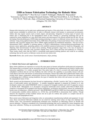
  • 4. 40 - r 35 -a d 30 ::-1 25 20 - 300 400 500 600 700 800 Printing Speed mm /min E E O O N E E O O E E OO00 [L(lr/! ®®®©®®©VA.i`C/e(<(l(((CL((E( ED®OO(.(;(c0C-(((c((((((( EpOOOOO®C,C((((((((((((C( OO OO©©OQCC(((((((((( 3. RESULTS AND DISCUSSION 3.1 Mask-less lithography The objective of using mask-less lithography for patterning metal traces on various substrates is to demonstrate the feasibility of EHD printing as a pattern transfer technique that is well suited for sensor integration onto robotic skin. Figure 3 shows printed KMPR patterns on gold coated silicon substrates. Modified KMPR was used as an EHD ink because it was designed for a similar kind of lithographic processes. Drop-on-demand printing was performed at a frequency of 600Hz with substrate speeds changing from 200 to 1000 mm/min. Data shows that the transition from dots to uniform lines occurs around a 600 mm/min stage speed. Further reducing the stage speed, the linewidth was increased. The linewidth as a function of stage speed is shown in figure 4. These particular printing conditions resulted in a line with a maximum height of 3 microns with a parabolic cross sectional shape. The parabolic line shape was expected due to surface tension driven restructuring. The process has been repeated on gold coated silicon oxide and Kapton substrates (data not shown) with similar results Figure 3. Variation of line shapes with respect to speeds for 600Hz drop-on demand KMPR printing. Printing speed was changed from 1000mm/min to 200mm/min while other conditions remained the same. Figure 4. The linewidth variation as a function of stage speed for drop-on demand KMPR printing at 600Hz. The viability of pattern transfer using EHD printed lines was evaluated using typical etching and resist removal processes. Figure 5 displays images of patterned gold lines on (a) silicon, (b) silicon oxide, and (c) Kapton clearly showing pattern transferability on various substrate materials. Most robotic skins are fabricated using flexible substrates Proc. of SPIE Vol. 9116 91160F-4 Downloaded From: http://proceedings.spiedigitallibrary.org/ on 08/19/2014 Terms of Use: http://spiedl.org/terms
  • 5. (a) (b) 150µm A 2220µm < > ` 2160 µm of a size, shape, and topography that are not suited for conventional lithography. This data encourages replacing photolithography processes with direct EHD printing of photoresist for mask-less lithography-based patterning of metal interconnects and other materials for sensor integration onto robotic skin Figure 5. EHD-based mask-less lithography patterned gold lines on (a) silicon (linewidth 23.5μm), (b) silicon oxide (linewidth 31.3μm) and (c) Kapton (linewidth 16.8μm). 3.2 Printing PEDOT:PSS Sensing Layers In recent years, PEDOT:PSS has been the sensing material used in touch screen technology. PEDOT:PSS is a transparent, conjugated conducting polymer that is highly ductile and stretchable along with having good environmental stability. Several researchers have fabricated and characterized tactile sensors using PEDOT:PSS8,9,10,11 . The resistance of ink-jet printed PEDOT:PSS is about a few kilo ohms. It has elongation of 10% or more. The gauge factor of PEDOT:PSS is 5 to 20, whereas the gauge factor of a conventional metal film is 2. Calvert et al. fabricated piezoresistive sensors using PEDOT:PSS inkjet printing for smart textiles8 . That tactile sensor showed a resistance of 5 kilo Ohms and a gauge factor of 5 after 500 cycles of testing. Here we report the results of a first attempt at printing PEDOT:PSS in order to fabricate pressure and strain sensors as well as interconnects on robotic skin. Figure 6 shows the printing results for an array of interconnected square pads printed on a gold coated glass substrate. By examining the results as printed, it is apparent that solvent pooling and surface tension-driven restructuring are occurring. Currently, optimization of the PEDOT:PSS ink and printing process is progressing to mitigate this issue. Future plans include characterization of the printed material and implementation of the printing process to tactile sensor fabrication on skin like substrates. Figure 6. The results of an array of interconnected square pads printed on gold coated glass substrate (a) as printed and (b) after room temperature drying for three hours. 3.3 Printing Metal Oxide Microstructures As multifunctional materials, metal oxides are poised to play a critical role in many advanced technologies that include flat panel displays, printed electronics, sensors, and actuators. Although printing and fabrication methods described here may not lead to fabrication of these devices directly onto robotic skin due a high temperature processing step, EHD Proc. of SPIE Vol. 9116 91160F-5 Downloaded From: http://proceedings.spiedigitallibrary.org/ on 08/19/2014 Terms of Use: http://spiedl.org/terms
  • 6. et A's 60 c0 50 v 40 3 c 30 I 600 500 £400 w /-Before Sintering 300 -After Sintering u 200 at 400QC :c100 400 800 1200 1600 2000 Priting Speed mm /min. o 450 470 490 510 Lateral Distance(pm) 450 doo (a) 350 r g é 250 e 200 ZnO (100] ¡ISO ) ó 100 4) o+wwrn,rwr 26 2,10 (0021 ZnO (1011 i two) ''41'414I.4444440" 30 32 34 36 38 40 2 -Tnela Scat! (b) printing can be used to integrate metal oxide-based miniature gas sensors, thin film transistors, and energy harvesters to other parts of a robotic platform. This investigation was focused on printing ZnO from a highly conductive (135µS/cm) zinc ion containing ink. The printing results discussed in this section not only demonstrate the formation of ZnO microstructures but also show the capability of EHD as a versatile printing method by printing non-conductive KMPR ink to highly conductive Zinc ion containing ink. After printing on a silicon oxide substrate, printed microstructures were subjected to a sintering process for creating ZnO microstructures. X-Ray Diffraction (XRD) analysis performed on the printed ZnO films sintered at various temperatures confirmed that the ink produces polycrystalline ZnO upon heating above 400ºC. Figure 7(a) displays the representative XRD data showing the polycrystalline nature of the sintered film. Figure 7(b) shows the SEM image of formed ZnO lines with no detectable cracks or pinholes. Further investigation is needed to better understand the effect of matrix loading and sintering on grain characteristics and film stress. Figure 7. (a) the representative XRD data of the sintered ZnO film at 400ºC and (b) the SEM image of ZnO microstructure. Figure 8 (a) shows the linewidth of the printed structures based on printing speed using at an jetting voltage of 850V. After the sintering process, one of the key aspects to note is the shrinkage of the structure due to the removal of matrix materials. It is therefore essential to build a correlation between printed and final microstructure geometry in order to obtain desired device geometry. Figure 8 (b) shows the representative surface profile of ZnO ink printed at 850V with a printing speed of 1000 mm/min before and after sintering. The lateral and thickness shrinkage percentage for this particular ink were determined to be 3% and 92% respectively. With the negligible lateral shrinkage, this printing has resulted in ZnO microstructures with linewidths ranging from 18 to 65µm and thicknesses ranging from 33 to 62nm. The capability of printing a wide range of thickness by changing process parameters is encouraging as this can lead to different types of device using EHD. Figure 8. (a) Linewidth of printed structures as a function of printing speed using a jetting voltage of 850V and (b) surface profile data on ZnO ink printed at 850V with a printing speed of 1000 mm/min before and after sintering. 4. CONCLUSIONS AND FUTURE DIRECTIONS Based on the preliminary experimental work performed here, it is evident that EHD printing could be an attractive method for integrating sensors into robotic skins for human-robot interactions. We have shown the printing of high Proc. of SPIE Vol. 9116 91160F-6 Downloaded From: http://proceedings.spiedigitallibrary.org/ on 08/19/2014 Terms of Use: http://spiedl.org/terms
  • 7. viscosity materials with varying conductivity and the ability to achieve geometries ranging from a few tens of microns to millimeters. This clearly shows that the EHD is an enabling technology that can be used to co-fabricate various devices onto a single substrate. Although many technological advancements are necessary to fully tap the potential of EHD, the experimental results discussed here evidently show the possibility of EHD as a manufacturing platform for integrating sensors into robotic skin. Our immediate future research is focused on two main areas: (1) further development of the EHD printer technology, and (2) fabricating an array of pressure sensors onto flexible substrates by printing PEDOT:PSS. The primary goal of EHD technology development is to integrate a ring electrode to the nozzle head so that printing can be performed regardless of substrate conductivity. Though several attempts have been made by a few research groups to integrate ring electrodes into EHD printers, this is a major technological barrier that hampers the application of EHD printing technology to a wide array of substrates. In terms of sensors for robotic skins, we plan to fabricate an array of pressure sensors onto a flexible substrate by using EHD printing. The work will starts with characterization of printed materials and ends with the fabrication of an entire sensor array by printing PEDOT:PSS and interconnects using EHD. 5. ACKNOWLEDGMENTS This work was supported in part by the Office of Naval Research Grants #N00014-08-C-0390, #N00014-11-C-0391, and the National Science Foundation NRI Grant #IIS-1208623. We wish to thank Raminderdeep Sidhu, Lester Corwin, and the UTA Research Institute staff for their help with the experimental work presented in this paper. REFERENCES [1] Schmitz, A., Maiolino, P., Maggiali, M., Natale, L., Cannata, G., and Metta, G., “Methods and Technologies for the Implementation of Large-Scale Robot Tactile Sensors,” IEEE Trans. on Robotics, Vol. 27, No. 3, pp. 389-400, June 2011. [2] Mittendorfer, P. and Cheng, G., “Humanoid Multi-Modal Tactile Sensing Modules,” IEEE Trans. on Robotics, Vol. 27, No. 3, pp. 401-410, June 2011. [3] Chen, C.-H., Saville, D. A., and Aksay, I. A., “Scaling laws for pulsed electrohydrodynamic drop formation,” Applied Physics Letters 89, 12410, 2006. [4] Lee, D.-Y., Lee, J.-C., Shin, Y.-S., Park, S.-E., Yu, T.-U., Kim, Y.-J. and Hwang, J., “Structuring of conductive silver line by electrohydrodynamic jet printing and its electrical characterization,” Journal of Physics: Conference Series 142, 012039, 2008. [5] Sidhu, R., Sin, J., Lee, W. H., Stephanou, H. E., and Wijesundara, M.B.J., “Electrohydrodynamic printing of metal oxide microstructures,” International Conference On Micromanufacturing, pp. 458-461, 2012 [6] Choi, J., Kim, Y.-J., Son, S. U., An, K. C., and Lee, S., “The investigation of electrostatic induced inkjet printing system,” Nanotech, pp. 464-467, 2010. [7] http://www.microchem.com/pdf/KMPRDataSheetver4_2a.htm [8] Calvert, P., Patra, P., Lo, T-C., Chen, C., Sawhney, A., and Agrawal, A., “Piezoresistive sensors for smart textiles,” Proc. SPIE 6524, Electroactive Polymer Actuators and Devices, 2007. [9] Latessa, G., Brunetti, F., Reale, A., Saggio, G., and Carlo, A. D., “Piezoresistive behavior of flexible PEDOT:PSS based sensors,” Sensors and Actuators B: Chemical, Vol. 139, Issue 2, pp. 304-309, June 2009. [10]Lang, U., Rust, P., and Dual, J., “Towards fully polymeric MEMS: Fabrication and testing of PEDOT/PSS strain gauges,” Proc. Micro- and Nano-Engineering, pp. 1050-1053, MNE 2007. [11]Takamatsu, S. and Itoh, T., “Novel MEMS Devices Based on Conductive Polymers,” Electrochemical Society, Interface, 2012. Proc. of SPIE Vol. 9116 91160F-7 Downloaded From: http://proceedings.spiedigitallibrary.org/ on 08/19/2014 Terms of Use: http://spiedl.org/terms