SlideShare uma empresa Scribd logo
1 de 4
Name Muhammad Talha Saeed
Reg. # 19-NTU-TE-0129
Experiment 4:
Demonstrate the behavior of semiconductor diodes in half-wave and full-wave
rectifiers both with and without capacitor filter
Apparatus:
Electro-Technic Lab Trainer,
Oscilloscope,
Digital Multi-meter,
Connecting leads.
Half-wave rectifier without and with capacitor filter
Circuit Diagram
a) b)
Figure 1 Half-wave rectifier a) without and b) with capacitor filter
Procedure
1. Connect the circuit as shown in Figure 8 a) using Electro-technic Lab Trainer and
Connecting leads.
2. Connect one of the probes of the oscilloscope across the output terminals of the transformer
and the second probe across the load resistor R.
3. Turn on the scope, set the channel selector to “Dual” mode, and coupling to DC. View both
of the signals simultaneously with proper voltage and position setting.
4. Set the selector switch of the multi-meter at AC voltage range.
5. Measure the AC voltage across the output terminals of the transformer using DMM and
record the reading.
11.31 V
6. Measure the DC voltage across the load resistor with the help of digital multi-meter and
record.
4.78 V
7. Paste picture of the output voltage observed by the oscilloscope in the following chart.
WhatsApp Video 2022-04-04 at 11.30.42 AM.mp4
Double click on video icon to open this
8. Measure the output frequency and record.
T = 4x5 ms = 20 ms = 0.02 s
f = 1/T = 1/0.02
f = 50 Hz
9. Measure the peak value of the output voltage of the half-wave rectifier with the help of
oscilloscope and record.
= 3.4 x 5
= 17
10. Now, connect the capacitor filter across the load resistor as in Figure 8 b).
11. Paste picture of the output voltage observed by the oscilloscope in the following chart.
WhatsApp Video 2022-04-04 at 11.30.42 AM (1).mp4
Double click on video icon to open this
Full-wave rectifier without and with capacitor filter
Circuit Diagram
a) b)
Figure 2 Full-wave rectifier a) without and b) with capacitor filter
Procedure
1. Connect the circuit as shown in Figure 9 a) using Electro-technic Lab Trainer and
Connecting leads.
2. Connect one of the probes of the oscilloscope across the output terminals of the transformer
and the second probe across the load resistor R.
3. Turn on the scope, set the channel selector to “Dual” mode, and coupling to DC. View both
of the signals simultaneously with proper voltage and position setting.
4. Set the selector switch of the multi-meter at AC voltage range.
5. Measure the AC voltage across the output terminals of the transformer using DMM and
record the reading.
11.05 V
6. Measure the DC voltage across the load resistor with the help of multi-meter and record.
8.74 V
7. Measure the peak value of the output of the full-wave rectifier with the help of oscilloscope
and record.
= 3.3 x 5
= 17
8. Measure the output frequency and record.
T = 2x5 ms = 10 ms = 0.01 s
f = 1/T = 1/0.01
f = 100 Hz
9. Paste picture of the output voltage observed by the oscilloscope in the following chart.
WhatsApp Video 2022-04-04 at 11.30.43 AM (1).mp4
Double click on video icon to open this
10. Now, connect the capacitor filter across the load resistor as in Figure 9 b).
11. Paste picture of the output voltage observed by the oscilloscope in the following chart.
WhatsApp Video 2022-04-04 at 11.30.43 AM (3).mp4
Double click on video icon to open this
Interpretation and Analysis
Is there any frequency difference between half- and full-wave rectifier? If yes, then
why?
Yes frequency is different in half wave and full wave rectifier for same input frequency. In half
wave the output frequency is same as input frequency. As it allows only a half cycle of AC
input voltage. While in case of full wave rectifier the output frequency is twice the input
frequency as it allows full cycle of AC input voltages to pass.
Is there any difference between magnitude of DC output voltage of half- and full-wave
rectifier? If yes, then why?
Yes there is difference between magnitude of DC output voltage of Half and Full-wave
rectifier. Because in half wave only half input cycle is rectified while in full wave whole cycle
is rectified so out put voltage of full wave rectifier is higher.
Conclusion
From the experiment, results and above discussion it is concluded that both half wave and full
wave rectifiers are used to transform AC into pulsating DC. Only the variation is the utilization
of an applied input signal. However, pulsating dc output shows that some AC ripples are also
present in it. So, it must be as small as possible. But the AC ripples in case of half wave
rectifier is somewhat more as compared to full wave rectifier.

Mais conteúdo relacionado

Semelhante a EE Lab 4 Manual.docx

Performance Evaluation of Nine Level Modified CHB Multilevel Inverter for Var...
Performance Evaluation of Nine Level Modified CHB Multilevel Inverter for Var...Performance Evaluation of Nine Level Modified CHB Multilevel Inverter for Var...
Performance Evaluation of Nine Level Modified CHB Multilevel Inverter for Var...IJMER
 
A Simple Strategy of Controlling a Balanced Voltage Capacitor in Single Phase...
A Simple Strategy of Controlling a Balanced Voltage Capacitor in Single Phase...A Simple Strategy of Controlling a Balanced Voltage Capacitor in Single Phase...
A Simple Strategy of Controlling a Balanced Voltage Capacitor in Single Phase...IAES-IJPEDS
 
Switching Voltage Regulator
Switching Voltage RegulatorSwitching Voltage Regulator
Switching Voltage Regulatoribercovich
 
Pulse amplitude modulation
Pulse amplitude modulationPulse amplitude modulation
Pulse amplitude modulationVishal kakade
 
A Non-isolated Hybrid Boost Three Level DC-DC Converter with High Step-up Con...
A Non-isolated Hybrid Boost Three Level DC-DC Converter with High Step-up Con...A Non-isolated Hybrid Boost Three Level DC-DC Converter with High Step-up Con...
A Non-isolated Hybrid Boost Three Level DC-DC Converter with High Step-up Con...IJSRD
 
A new precision peak detector full wave rectifier
A new precision peak detector full wave rectifierA new precision peak detector full wave rectifier
A new precision peak detector full wave rectifierVishal kakade
 
Introduction to Oscilloscope and Function generator
Introduction to Oscilloscope and Function generatorIntroduction to Oscilloscope and Function generator
Introduction to Oscilloscope and Function generatorcyberns_
 
Simulated Analysis of Resonant Frequency Converter Using Different Tank Circu...
Simulated Analysis of Resonant Frequency Converter Using Different Tank Circu...Simulated Analysis of Resonant Frequency Converter Using Different Tank Circu...
Simulated Analysis of Resonant Frequency Converter Using Different Tank Circu...IJERD Editor
 
Investigation of THD for Cascaded Multi-Level Inverter Using Multicarrier Mod...
Investigation of THD for Cascaded Multi-Level Inverter Using Multicarrier Mod...Investigation of THD for Cascaded Multi-Level Inverter Using Multicarrier Mod...
Investigation of THD for Cascaded Multi-Level Inverter Using Multicarrier Mod...IJERA Editor
 
COMPREHENSIVE ANALYSIS AND SIMULATION OF MULTILEVEL POWER CONVERTERS TO CURTA...
COMPREHENSIVE ANALYSIS AND SIMULATION OF MULTILEVEL POWER CONVERTERS TO CURTA...COMPREHENSIVE ANALYSIS AND SIMULATION OF MULTILEVEL POWER CONVERTERS TO CURTA...
COMPREHENSIVE ANALYSIS AND SIMULATION OF MULTILEVEL POWER CONVERTERS TO CURTA...ecij
 
Multilevel inverter fault detectiion classification and diagnosis
Multilevel inverter fault detectiion classification and diagnosisMultilevel inverter fault detectiion classification and diagnosis
Multilevel inverter fault detectiion classification and diagnosissuryakant tripathi
 
Modified Bidirectional Converter with Current Fed Inverter
Modified Bidirectional Converter with Current Fed InverterModified Bidirectional Converter with Current Fed Inverter
Modified Bidirectional Converter with Current Fed InverterIJPEDS-IAES
 

Semelhante a EE Lab 4 Manual.docx (20)

Pdc lab manualnew
Pdc lab manualnewPdc lab manualnew
Pdc lab manualnew
 
Gopi 1 lab manual
Gopi 1 lab manualGopi 1 lab manual
Gopi 1 lab manual
 
Experiment 4
Experiment 4Experiment 4
Experiment 4
 
Performance Evaluation of Nine Level Modified CHB Multilevel Inverter for Var...
Performance Evaluation of Nine Level Modified CHB Multilevel Inverter for Var...Performance Evaluation of Nine Level Modified CHB Multilevel Inverter for Var...
Performance Evaluation of Nine Level Modified CHB Multilevel Inverter for Var...
 
A Simple Strategy of Controlling a Balanced Voltage Capacitor in Single Phase...
A Simple Strategy of Controlling a Balanced Voltage Capacitor in Single Phase...A Simple Strategy of Controlling a Balanced Voltage Capacitor in Single Phase...
A Simple Strategy of Controlling a Balanced Voltage Capacitor in Single Phase...
 
D05432435
D05432435D05432435
D05432435
 
Solved problems on rectifiers
Solved problems  on rectifiersSolved problems  on rectifiers
Solved problems on rectifiers
 
Lab1
Lab1Lab1
Lab1
 
Switching Voltage Regulator
Switching Voltage RegulatorSwitching Voltage Regulator
Switching Voltage Regulator
 
Pulse amplitude modulation
Pulse amplitude modulationPulse amplitude modulation
Pulse amplitude modulation
 
A Non-isolated Hybrid Boost Three Level DC-DC Converter with High Step-up Con...
A Non-isolated Hybrid Boost Three Level DC-DC Converter with High Step-up Con...A Non-isolated Hybrid Boost Three Level DC-DC Converter with High Step-up Con...
A Non-isolated Hybrid Boost Three Level DC-DC Converter with High Step-up Con...
 
A new precision peak detector full wave rectifier
A new precision peak detector full wave rectifierA new precision peak detector full wave rectifier
A new precision peak detector full wave rectifier
 
Introduction to Oscilloscope and Function generator
Introduction to Oscilloscope and Function generatorIntroduction to Oscilloscope and Function generator
Introduction to Oscilloscope and Function generator
 
Simulated Analysis of Resonant Frequency Converter Using Different Tank Circu...
Simulated Analysis of Resonant Frequency Converter Using Different Tank Circu...Simulated Analysis of Resonant Frequency Converter Using Different Tank Circu...
Simulated Analysis of Resonant Frequency Converter Using Different Tank Circu...
 
[IJET V2I5P10] Authors: Vinith Das, Dr. Babu Paul, Prof. Elizabeth Seba stian
[IJET V2I5P10] Authors: Vinith Das, Dr. Babu Paul, Prof. Elizabeth Seba stian [IJET V2I5P10] Authors: Vinith Das, Dr. Babu Paul, Prof. Elizabeth Seba stian
[IJET V2I5P10] Authors: Vinith Das, Dr. Babu Paul, Prof. Elizabeth Seba stian
 
Investigation of THD for Cascaded Multi-Level Inverter Using Multicarrier Mod...
Investigation of THD for Cascaded Multi-Level Inverter Using Multicarrier Mod...Investigation of THD for Cascaded Multi-Level Inverter Using Multicarrier Mod...
Investigation of THD for Cascaded Multi-Level Inverter Using Multicarrier Mod...
 
COMPREHENSIVE ANALYSIS AND SIMULATION OF MULTILEVEL POWER CONVERTERS TO CURTA...
COMPREHENSIVE ANALYSIS AND SIMULATION OF MULTILEVEL POWER CONVERTERS TO CURTA...COMPREHENSIVE ANALYSIS AND SIMULATION OF MULTILEVEL POWER CONVERTERS TO CURTA...
COMPREHENSIVE ANALYSIS AND SIMULATION OF MULTILEVEL POWER CONVERTERS TO CURTA...
 
COMPREHENSIVE ANALYSIS AND SIMULATION OF MULTILEVEL POWER CONVERTERS TO CURTA...
COMPREHENSIVE ANALYSIS AND SIMULATION OF MULTILEVEL POWER CONVERTERS TO CURTA...COMPREHENSIVE ANALYSIS AND SIMULATION OF MULTILEVEL POWER CONVERTERS TO CURTA...
COMPREHENSIVE ANALYSIS AND SIMULATION OF MULTILEVEL POWER CONVERTERS TO CURTA...
 
Multilevel inverter fault detectiion classification and diagnosis
Multilevel inverter fault detectiion classification and diagnosisMultilevel inverter fault detectiion classification and diagnosis
Multilevel inverter fault detectiion classification and diagnosis
 
Modified Bidirectional Converter with Current Fed Inverter
Modified Bidirectional Converter with Current Fed InverterModified Bidirectional Converter with Current Fed Inverter
Modified Bidirectional Converter with Current Fed Inverter
 

Último

Configuration of IoT devices - Systems managament
Configuration of IoT devices - Systems managamentConfiguration of IoT devices - Systems managament
Configuration of IoT devices - Systems managamentBharaniDharan195623
 
Sachpazis Costas: Geotechnical Engineering: A student's Perspective Introduction
Sachpazis Costas: Geotechnical Engineering: A student's Perspective IntroductionSachpazis Costas: Geotechnical Engineering: A student's Perspective Introduction
Sachpazis Costas: Geotechnical Engineering: A student's Perspective IntroductionDr.Costas Sachpazis
 
BSNL Internship Training presentation.pptx
BSNL Internship Training presentation.pptxBSNL Internship Training presentation.pptx
BSNL Internship Training presentation.pptxNiranjanYadav41
 
Comparative study of High-rise Building Using ETABS,SAP200 and SAFE., SAFE an...
Comparative study of High-rise Building Using ETABS,SAP200 and SAFE., SAFE an...Comparative study of High-rise Building Using ETABS,SAP200 and SAFE., SAFE an...
Comparative study of High-rise Building Using ETABS,SAP200 and SAFE., SAFE an...Erbil Polytechnic University
 
Autonomous emergency braking system (aeb) ppt.ppt
Autonomous emergency braking system (aeb) ppt.pptAutonomous emergency braking system (aeb) ppt.ppt
Autonomous emergency braking system (aeb) ppt.pptbibisarnayak0
 
CCS355 Neural Networks & Deep Learning Unit 1 PDF notes with Question bank .pdf
CCS355 Neural Networks & Deep Learning Unit 1 PDF notes with Question bank .pdfCCS355 Neural Networks & Deep Learning Unit 1 PDF notes with Question bank .pdf
CCS355 Neural Networks & Deep Learning Unit 1 PDF notes with Question bank .pdfAsst.prof M.Gokilavani
 
Energy Awareness training ppt for manufacturing process.pptx
Energy Awareness training ppt for manufacturing process.pptxEnergy Awareness training ppt for manufacturing process.pptx
Energy Awareness training ppt for manufacturing process.pptxsiddharthjain2303
 
US Department of Education FAFSA Week of Action
US Department of Education FAFSA Week of ActionUS Department of Education FAFSA Week of Action
US Department of Education FAFSA Week of ActionMebane Rash
 
Main Memory Management in Operating System
Main Memory Management in Operating SystemMain Memory Management in Operating System
Main Memory Management in Operating SystemRashmi Bhat
 
welding defects observed during the welding
welding defects observed during the weldingwelding defects observed during the welding
welding defects observed during the weldingMuhammadUzairLiaqat
 
Ch10-Global Supply Chain - Cadena de Suministro.pdf
Ch10-Global Supply Chain - Cadena de Suministro.pdfCh10-Global Supply Chain - Cadena de Suministro.pdf
Ch10-Global Supply Chain - Cadena de Suministro.pdfChristianCDAM
 
Engineering Drawing section of solid
Engineering Drawing     section of solidEngineering Drawing     section of solid
Engineering Drawing section of solidnamansinghjarodiya
 
Risk Management in Engineering Construction Project
Risk Management in Engineering Construction ProjectRisk Management in Engineering Construction Project
Risk Management in Engineering Construction ProjectErbil Polytechnic University
 
multiple access in wireless communication
multiple access in wireless communicationmultiple access in wireless communication
multiple access in wireless communicationpanditadesh123
 
Arduino_CSE ece ppt for working and principal of arduino.ppt
Arduino_CSE ece ppt for working and principal of arduino.pptArduino_CSE ece ppt for working and principal of arduino.ppt
Arduino_CSE ece ppt for working and principal of arduino.pptSAURABHKUMAR892774
 
Earthing details of Electrical Substation
Earthing details of Electrical SubstationEarthing details of Electrical Substation
Earthing details of Electrical Substationstephanwindworld
 
Internet of things -Arshdeep Bahga .pptx
Internet of things -Arshdeep Bahga .pptxInternet of things -Arshdeep Bahga .pptx
Internet of things -Arshdeep Bahga .pptxVelmuruganTECE
 
"Exploring the Essential Functions and Design Considerations of Spillways in ...
"Exploring the Essential Functions and Design Considerations of Spillways in ..."Exploring the Essential Functions and Design Considerations of Spillways in ...
"Exploring the Essential Functions and Design Considerations of Spillways in ...Erbil Polytechnic University
 
UNIT III ANALOG ELECTRONICS (BASIC ELECTRONICS)
UNIT III ANALOG ELECTRONICS (BASIC ELECTRONICS)UNIT III ANALOG ELECTRONICS (BASIC ELECTRONICS)
UNIT III ANALOG ELECTRONICS (BASIC ELECTRONICS)Dr SOUNDIRARAJ N
 

Último (20)

Configuration of IoT devices - Systems managament
Configuration of IoT devices - Systems managamentConfiguration of IoT devices - Systems managament
Configuration of IoT devices - Systems managament
 
Sachpazis Costas: Geotechnical Engineering: A student's Perspective Introduction
Sachpazis Costas: Geotechnical Engineering: A student's Perspective IntroductionSachpazis Costas: Geotechnical Engineering: A student's Perspective Introduction
Sachpazis Costas: Geotechnical Engineering: A student's Perspective Introduction
 
BSNL Internship Training presentation.pptx
BSNL Internship Training presentation.pptxBSNL Internship Training presentation.pptx
BSNL Internship Training presentation.pptx
 
Comparative study of High-rise Building Using ETABS,SAP200 and SAFE., SAFE an...
Comparative study of High-rise Building Using ETABS,SAP200 and SAFE., SAFE an...Comparative study of High-rise Building Using ETABS,SAP200 and SAFE., SAFE an...
Comparative study of High-rise Building Using ETABS,SAP200 and SAFE., SAFE an...
 
Autonomous emergency braking system (aeb) ppt.ppt
Autonomous emergency braking system (aeb) ppt.pptAutonomous emergency braking system (aeb) ppt.ppt
Autonomous emergency braking system (aeb) ppt.ppt
 
CCS355 Neural Networks & Deep Learning Unit 1 PDF notes with Question bank .pdf
CCS355 Neural Networks & Deep Learning Unit 1 PDF notes with Question bank .pdfCCS355 Neural Networks & Deep Learning Unit 1 PDF notes with Question bank .pdf
CCS355 Neural Networks & Deep Learning Unit 1 PDF notes with Question bank .pdf
 
Designing pile caps according to ACI 318-19.pptx
Designing pile caps according to ACI 318-19.pptxDesigning pile caps according to ACI 318-19.pptx
Designing pile caps according to ACI 318-19.pptx
 
Energy Awareness training ppt for manufacturing process.pptx
Energy Awareness training ppt for manufacturing process.pptxEnergy Awareness training ppt for manufacturing process.pptx
Energy Awareness training ppt for manufacturing process.pptx
 
US Department of Education FAFSA Week of Action
US Department of Education FAFSA Week of ActionUS Department of Education FAFSA Week of Action
US Department of Education FAFSA Week of Action
 
Main Memory Management in Operating System
Main Memory Management in Operating SystemMain Memory Management in Operating System
Main Memory Management in Operating System
 
welding defects observed during the welding
welding defects observed during the weldingwelding defects observed during the welding
welding defects observed during the welding
 
Ch10-Global Supply Chain - Cadena de Suministro.pdf
Ch10-Global Supply Chain - Cadena de Suministro.pdfCh10-Global Supply Chain - Cadena de Suministro.pdf
Ch10-Global Supply Chain - Cadena de Suministro.pdf
 
Engineering Drawing section of solid
Engineering Drawing     section of solidEngineering Drawing     section of solid
Engineering Drawing section of solid
 
Risk Management in Engineering Construction Project
Risk Management in Engineering Construction ProjectRisk Management in Engineering Construction Project
Risk Management in Engineering Construction Project
 
multiple access in wireless communication
multiple access in wireless communicationmultiple access in wireless communication
multiple access in wireless communication
 
Arduino_CSE ece ppt for working and principal of arduino.ppt
Arduino_CSE ece ppt for working and principal of arduino.pptArduino_CSE ece ppt for working and principal of arduino.ppt
Arduino_CSE ece ppt for working and principal of arduino.ppt
 
Earthing details of Electrical Substation
Earthing details of Electrical SubstationEarthing details of Electrical Substation
Earthing details of Electrical Substation
 
Internet of things -Arshdeep Bahga .pptx
Internet of things -Arshdeep Bahga .pptxInternet of things -Arshdeep Bahga .pptx
Internet of things -Arshdeep Bahga .pptx
 
"Exploring the Essential Functions and Design Considerations of Spillways in ...
"Exploring the Essential Functions and Design Considerations of Spillways in ..."Exploring the Essential Functions and Design Considerations of Spillways in ...
"Exploring the Essential Functions and Design Considerations of Spillways in ...
 
UNIT III ANALOG ELECTRONICS (BASIC ELECTRONICS)
UNIT III ANALOG ELECTRONICS (BASIC ELECTRONICS)UNIT III ANALOG ELECTRONICS (BASIC ELECTRONICS)
UNIT III ANALOG ELECTRONICS (BASIC ELECTRONICS)
 

EE Lab 4 Manual.docx

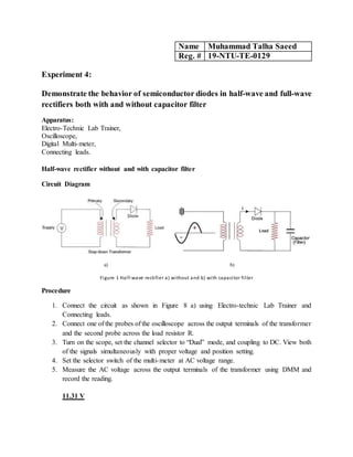
  • 1. Name Muhammad Talha Saeed Reg. # 19-NTU-TE-0129 Experiment 4: Demonstrate the behavior of semiconductor diodes in half-wave and full-wave rectifiers both with and without capacitor filter Apparatus: Electro-Technic Lab Trainer, Oscilloscope, Digital Multi-meter, Connecting leads. Half-wave rectifier without and with capacitor filter Circuit Diagram a) b) Figure 1 Half-wave rectifier a) without and b) with capacitor filter Procedure 1. Connect the circuit as shown in Figure 8 a) using Electro-technic Lab Trainer and Connecting leads. 2. Connect one of the probes of the oscilloscope across the output terminals of the transformer and the second probe across the load resistor R. 3. Turn on the scope, set the channel selector to “Dual” mode, and coupling to DC. View both of the signals simultaneously with proper voltage and position setting. 4. Set the selector switch of the multi-meter at AC voltage range. 5. Measure the AC voltage across the output terminals of the transformer using DMM and record the reading. 11.31 V
  • 2. 6. Measure the DC voltage across the load resistor with the help of digital multi-meter and record. 4.78 V 7. Paste picture of the output voltage observed by the oscilloscope in the following chart. WhatsApp Video 2022-04-04 at 11.30.42 AM.mp4 Double click on video icon to open this 8. Measure the output frequency and record. T = 4x5 ms = 20 ms = 0.02 s f = 1/T = 1/0.02 f = 50 Hz 9. Measure the peak value of the output voltage of the half-wave rectifier with the help of oscilloscope and record. = 3.4 x 5 = 17 10. Now, connect the capacitor filter across the load resistor as in Figure 8 b). 11. Paste picture of the output voltage observed by the oscilloscope in the following chart. WhatsApp Video 2022-04-04 at 11.30.42 AM (1).mp4 Double click on video icon to open this
  • 3. Full-wave rectifier without and with capacitor filter Circuit Diagram a) b) Figure 2 Full-wave rectifier a) without and b) with capacitor filter Procedure 1. Connect the circuit as shown in Figure 9 a) using Electro-technic Lab Trainer and Connecting leads. 2. Connect one of the probes of the oscilloscope across the output terminals of the transformer and the second probe across the load resistor R. 3. Turn on the scope, set the channel selector to “Dual” mode, and coupling to DC. View both of the signals simultaneously with proper voltage and position setting. 4. Set the selector switch of the multi-meter at AC voltage range. 5. Measure the AC voltage across the output terminals of the transformer using DMM and record the reading. 11.05 V 6. Measure the DC voltage across the load resistor with the help of multi-meter and record. 8.74 V 7. Measure the peak value of the output of the full-wave rectifier with the help of oscilloscope and record. = 3.3 x 5 = 17 8. Measure the output frequency and record. T = 2x5 ms = 10 ms = 0.01 s f = 1/T = 1/0.01 f = 100 Hz 9. Paste picture of the output voltage observed by the oscilloscope in the following chart.
  • 4. WhatsApp Video 2022-04-04 at 11.30.43 AM (1).mp4 Double click on video icon to open this 10. Now, connect the capacitor filter across the load resistor as in Figure 9 b). 11. Paste picture of the output voltage observed by the oscilloscope in the following chart. WhatsApp Video 2022-04-04 at 11.30.43 AM (3).mp4 Double click on video icon to open this Interpretation and Analysis Is there any frequency difference between half- and full-wave rectifier? If yes, then why? Yes frequency is different in half wave and full wave rectifier for same input frequency. In half wave the output frequency is same as input frequency. As it allows only a half cycle of AC input voltage. While in case of full wave rectifier the output frequency is twice the input frequency as it allows full cycle of AC input voltages to pass. Is there any difference between magnitude of DC output voltage of half- and full-wave rectifier? If yes, then why? Yes there is difference between magnitude of DC output voltage of Half and Full-wave rectifier. Because in half wave only half input cycle is rectified while in full wave whole cycle is rectified so out put voltage of full wave rectifier is higher. Conclusion From the experiment, results and above discussion it is concluded that both half wave and full wave rectifiers are used to transform AC into pulsating DC. Only the variation is the utilization of an applied input signal. However, pulsating dc output shows that some AC ripples are also present in it. So, it must be as small as possible. But the AC ripples in case of half wave rectifier is somewhat more as compared to full wave rectifier.