

Recomendados
Mais conteúdo relacionado
Mais procurados
Mais procurados (20)
Semelhante a Butterworth filter design
Semelhante a Butterworth filter design (20)
Último
Último (20)
Butterworth filter design
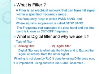
- 1. What is Filter ? A Filter is an electrical network that can transmit signal within a specified frequency range . This Frequency range is called PASS BAND and Where signal is suppressed is called STOP BAND. The Frequency that separates the pass band and the stop band is known as CUT-OFF frequency. What is Digital filter and why we use it ? Type of filter – 1) Analog filter 2) Digital filter Digital filter use to eliminate the Noise and to Extract the signal of interest from the other signal . Filtering is not done by RLC it done by using Difference eqn. It is implement using software like C and Assemble .
- 2. Types of Digital Filter – Depending on the no. of sample point used to determine the unit sample (impulse response)of LTI system ,digital filter are 2 types – 1)FIR(finite impulse response)filter 2)IIR(infinite impulse response)filter What is Ideal Filter? An ideal filter is would transmit signal under the pass band without attenuation and completely suppress the signal in stop band. Characteristics – it have constant gain in pass band and zero gain in the stop band. It has linear phase response. It must be causal .
- 3. Ideal filter can not be realize . IIR Filter Design – first design analog IIR filter. Then analog filter converted into the digital filter . Methods – 1) Impulse Invariant method – In this, we match the analog filter impulse response to the digital response. 2) Approximation of derivative method – In this ,differential equation of analog filter transform into difference equation of digital filter. 3) Bilinear method— In this, conformal mapping is done which transform the jΩ-Axis into the unit circle in the Z-plane.
- 4. What is basic analog filter Approximation? Approximation of analog filter is required because the practical characteristic of a filter is not identical to ideal characteristic . The approximation are 3 types - 1)Butterworth filter approximation 2) Chebyshev filter approximation 3) Elliptic filter approximation Note- The approximation is used for achieve ideal characteristic where as the methods are use to transform the analog filter response to digital filter response. we use transformation methods for designing of ideal characteristic.
- 5. Butterworth Filter For low pass filter.
- 6. The main characteristic of Butterworth filter is that the pass band is maximally flat. There are no variation (ripples) in the pass band. The magnitude response of LP Butterworth filter is given by - Where Ωc =cut off frequency |H(Ω)|2 =magnitude of LPF N= order of filter ,that means the no. of stages used in the design of analog filter.
- 8. Designing of Butterworth filter Designing steps : Let - Ap=Attenuation in pass band As=Attenuation in stop band Ωp=pass band edge frequency Ωc=Cut off frequency Ωs=stop band edge frequency Step 1 : Calculation for frequency of analog filter. a) For impulse invariance method , Ω - frequency of analog filter ῳ - frequency of digital filter T – sampling time b) For bilinear transformation method ,
- 9. Step 2: Evaluate the order N – Step 3 : Calculate cut-off frequency – a) For impulse invariance method-