
Recommended
Recommended
More Related Content
Similar to deloronzo_autotronics_lab (1).pdf
Similar to deloronzo_autotronics_lab (1).pdf (20)
Recently uploaded
Recently uploaded (20)
deloronzo_autotronics_lab (1).pdf
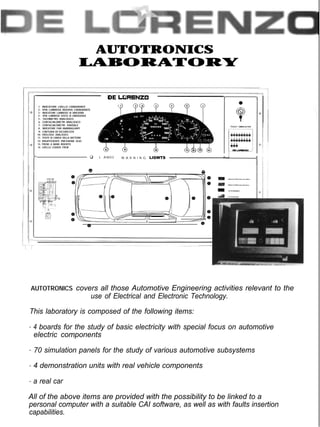
- 1. AUTOTRONICS ‘X’O’FRONI_(s!S LABORATORY 1: INDICATORE LIVELLO CARBURANTE 2 : SPIA LUMINOSA RISERVA CARBURANTE 3 : INDICATORE LUMINOSO DI DIREZIONE 4 : SPIA LUMINOSA SOSTA DI EMERGENZA 5 : TACHIMETRO ANALOGICO 6: CONTACHILOMETRI ANALOGICO 7: CONTACHILOMETRI PARZIALE 8: INDlCATORE FARI ANABBAGLIANTI 9: CINTURA DI SICUREZZA 10: OROLOGIO ANALOGICO 11: STATO DI CARICA DELLA BATTERIA 12: INSUFFICIENTE PRESSIONE OLIO 13: FRENO A MANO INSERITO 14: LIVELLO LIQUIDO FRENI DE LCaRENZO q L A M 0 3 W A R N I N G LIGWTS AUTOTRONICS covers all those Automotive Engineering activities relevant to the use of Electrical and Electronic Technology. This laboratory is composed of the following items: 4 boards for the study of basic electricity with special focus on automotive electric components 70 simulation panels for the study of various automotive subsystems 4 demonstration units with real vehicle components a real car All of the above items are provided with the possibility to be linked to a personal computer with a suitable CAI software, as well as with faults insertion capabilities.
- 2. This trainer has been developed to pro- vide the students with an excellent educational tool not only for the gra- dual learning of the basic theory, but also for the verification of the practical progress of the students. The student must, in a given time, study a circuit, understand the relevant theory, analyze the operating condi- tions and verify by means of suitable instrumentation, the situation at the various test points of the circuit. Once completed the experiment, the student must answer to a series of que- stions preprogrammed in the micropro- cessor. The latter guides the students through the various phases of the expe- riments: it automatically recognizes the module when inserted, it asks the stu- dent to insert his personal code, it pro- vides theoretical background, it asks questions, it inserts simulated faults and, finally, it places tests and gives a rating on the basis of the student performance. T I M E DC circuits - Voltmeter - Resistances and their recognition - Ohm's Law - Conductivity - Resistors in series - 1st Ohm's Law - Voltage dividers - Resistors in parallel - 2nd Kirchoff's Law - Current dividers - Circuits in parallel - series - Thevenin theorem - Norton theorem - Potentiometers - Hyperthesis theorem - Voltage sources - Maximum power transfer - Star and delta connection AC circuits - AC waveforms - Alternating current - Capacitors - RC circuits - Coils - RL circuits - Resonance - RC filters - RL filters - Band pass filters - Transformers - Electromagnets Automotive electric components and circuits - Voltage drop in series connection - Lamps - Automotive lights circuits - Relay Operating principles - Circuits with relays - Delay circuits with relay - Stop lights circuits (brakes) - Flash light circuits (direction indicators) - Diodes in light circuits - Diodes use for circuit separation - Thermistors in automotive circuits - Thermal switches - Angular deflection measurement using potentiometer - Fault finding Charging anti ignition circuits - AC generator (alternator) - Tachogenerator - AC to DC conversion - Automatic charging system - Hall effect switch - Strobe lights - Ignition excitation circuit with Hall switch - Induction coil - Ignition system - Fault finding Technical features -Robust structure and modern design - Gold plated terminals - Silk-screened circuit and identification of the components - Microprocessor: 7810 with 32 kb RAM, programmable through PC with C or Assembler compiler A/D 8 bit converter, 8 inputs 48 I/O lines 16 keys keypad LCD display, 4 lines, 40 characters/line, backlighted Board with 12 relays and 8 optoisolated inputs
- 3. This system consists of complete simulators on panel with printed schematics explaining the interconnections and the operation of typical automotive control systems. Schematic layouts of a vehicle show the location of the major components with test points and led indicators to represent system functions and outputs. The panels can be linked to a Personal Computer where a suitable software can demonstrate the relative theory as well as show graphically the operation on the computer. Also introduc- tion of system's basic faults is possible. The manuals provide a complete series of theory and exercises. DL AM01 Automotive air conditioning system Among others, the following subjects are covered: - Test instruments operation - Pressure/temperature relation in refrigerant - Operation principles of compressor, condenser - Pressure switches operation - Voltage measurement on electrical circuits (systems) DL AM02 Engine Starting Among others, the following subjects are covered: - Instruments (meter) operation -Voltage/resistance measurement - Starter operation - Ignition system - Operation and control of electronic circuits - Fuel system/operation - Electronic ignition DL AM03 Automotive electric circuits Among others, the following subjects are covered: -Electrical components -Electrical circuits -Electrical circuits faults, short-circuits, open circuits, bad components -Electrical components and their symbols -Automotive electric wiring -Troubleshooting method -Malfunctioning repair practical exercise DL AM04 Engine operation Among others, the following subjects are covered: -Temperature sensor operation -MAP sensor operation -Oxygen sensor operation -Knock sensor operation -Air injection control -Exhaust gas circuit -Ignition timings -Horsepower and engine torque -Engine efficiencies -Troubleshooting DL AM05 Engine sensors and controls Among others, the following subjects are covered: -Sensors operation -Temperature sensors -Pressure sensors -Flow sensors -Knock sensors -Position sensors -Oxygen sensors -Solenoids -Monitoring via computer -Open and close loop controls -Troubleshooting DL AM06 Emissions control system Among others, the following subjects are covered: -Internal combustion engines -Hydrocarbons, carbon monoxide and nitric oxides NOx measurements (emissions) -Exhaust gases (emissions) measurements -Stoichiometric air/fuel measurement -Early fuel evaporation -Idle air control -Evaporation emission Control -Exhaust gas sub-circuit (recirculation) -Catalyte -Fuel control -Air preheat systems DL AM07 Electric power subsystem Among others, the following subjects are covered: -Battery and power cables -Converter (alternator) -Voltage regulator -Starting system -Fuses and connections (fusible links) -Multiplier DL AM08 Electric components Among others, the following subjects are covered: - Digital instruments and display - Wipers - Cruise control - Radio/stereo system - Automatic lighting system - Electric seats with memories - Electric (power) windows - Alarm system DL AM09 Electrical components of big vehicles Among others, the following subjects are covered: - 12V circuits - Electric components - Electric circuits - Electric systems - Electric components and their symbols - Lorries electric wiring diagrams - Practical exercise on fault recognition and repair DL AM10 Big vehicles Starting Subsystem Among others, the following subjects are covered: - Digital meter operation - Ammeter operation - Battery voltage in terms of load and temperature - Battery charging and testing procedure - Cranking system - Loading procedure control system - Methods of recognizing faults - Repair's pactical techniques
- 4. DEMONSTRATION PANELS The integrated automotive technology laboratory includes also demonstrators with which practical exercises can be performed. The demonstrators are made with real automotive components to give the students a better understanding of the ope- rations. Also introduction of system's basic faults is possible. The manuals provide a complete series of theory and exer- cises, while an interactive software provides the students with multiple choice questions. DL DM01 DL DM03 H y d r a u l i c b r a k e s I g n i t i o n s y s t e m The demonstrator consists of a disk brake in the front wheel and a drum brake in the driving wheel. Both wheels are rotated slowly by means of an electric motor. When the brake is activated both wheels stop. The brake operates either by foot pedal or hand lever. The master cylinder is moved hydraulically. The auxiliary pump, the fluid pressure of the front disk brake are demonstrated on the unit. Also brake light are included and are lighted when the brake is activated. The panel has graphic diagrams to facilitate the comprehension of system operation. The system covers the following malfunctions: -Back wheel block, pressure does not drop after releasing pedal -Booster out of work, vacuum loss -Back brakes not functioning, leakage -Front brakes not functioning, leakage -Hard brakes -Brake lights, switch broken DL DM02 Electronic fuel injection Suitable to show how modern cars injection systems are designed to operate. The panel has graphic diagrams which provide comprehension of system operation. The experiments covered by the system are: -Relationship between the duration of injector opening to the quantity of injected fuel -Air temperature effect on the quantity of injected fuel -Signal analysis with oscilloscope -Injection time calculation with oscilloscope -Injection time calculation with tachometer and dwell meter -MAF sensor Operation -Valve position switch output signals -Valve position sensor output signals -Study of injector activation signal at various conditions -Ignition pulses effect on main switch -Injection duration at various speeds, temperatures and engine loads -Fuel cut off Suitable to show how modern cars ignition systems are designed to operate. All relative signals end to test points such as the output of Hall sensor, knock sensor output, engine speed, refrigerator temperature, MAP output, A/D input, voltage and current of initial ignition, voltage and current of secondary ignition (divided by 100), stroboscope trigger. The panel has graphic diagrams which provide comprehension of system operation. The experiments covered by the system are: -Direct ignition activation system -Different spark types analysis -Dwell timing and control -MAP sensor characteristics -Cooling sensor operation -Knock sensor characteristics -Constant current conservation for various engine speeds -Ignition system operation at various conditions of speed, load and engine temperature -Ignition time and dwell measurements -Operation of ignition system with fuel electronic injection DL DMO4 -Oxygen sensor operation ABS braking system Suitable to show how modern car ABS systems are designed to operate. The panel has graphic diagrams which provide comprehension of system operation. The experiments covered by the system are: -ABS operation when wheels are rotated at different speeds -ABS operation when wheels are rotated at same speed -Pressure measurement during operation -Hydraulic ABS valve operation -Self diagnostic control -Fault diagnosis procedure -Various control signals measurements in ABS system -Low fluid level detection -ABS operation with one wheel speed sensor disconnected -ABS operation with destroyed hydraulic valve -Brake system operation when the electronic brake unit is disconnected -Brakes operation when there is leakage -System operation with different relative rotation speed of wheels -ABS operation with hydraulic valve stuck REAL CAR The laboratory includes a real car into which fault insertion is done and is controlled by student workstation. In the car there is a system of inserting basic faults. The selection of fault is effected from the student workstation. Fault is displayed on student screen as customer complain (e.g. wipers are out of order), instructions are given to the student for finding procedure. The following areas are covered by the exercises in the real car: -Air and fuel input -Antipollution Controls -Automatic transmission -Brakes -Air conditioning -Heating -Cooling -Ignition -Fluid level Control -ABS System -Electronic controlled transmission -Wipers -Trip conditions control Viale Romagna, 20 - 20089 Rozzano (MI) ITALY Tel. +39 (2) 8254551 - Fax +39 (2) 8255181 E-mail: DE.LORENZO@GALACTICA.IT