SlideShare a Scribd company logo
1 of 27
Chapter 7
Coordinated Multipoint System
Abstract In this chapter, the application of multipoint cooperative communication
in the 4G networks, that is, the coordinated multipoint (CoMP) system, is addressed
from a variety of aspects. First, we review the development of CoMP in the
standardization of Long-Term Evolution-Advanced (LTE-A) networks and analyze
the reason of its preclusion from the LTE Release 10 specification. Second,
we discuss the renewed campaign of CoMP in LTE Release 11, including the
downlink transmission and uplink reception schemes of CoMP, as well as the related
specification works. Third, we analyze the simulation results from the 3GPP CoMP
study item to show the advantages of CoMP system in practical cellular networks.
Keywords CoMP • Implicit CSI feedback • CoMP scenarios • CoMP schemes
• Performance evaluation • LTE Release 8/9 • LTE Release 10 • LTE Release 11
7.1 Introduction
The formal discussions of multipoint cooperative communication technology in the
4G networks began in the Third Generation Partner Project (3GPP) technical spec-
ification group (TSG) radio access network (RAN) international mobile telecom-
munications (IMT) advanced workshop meeting (ETSI MCC 2008). Some well-
organized elaborations on this new technology within the standardization framework
can be found in Alcatel-Lucent (2008a). In the Long-Term Evolution-Advanced
(LTE-A) network, cooperative communication scheme is generally named coordi-
nated multipoint (CoMP) transmission or reception, which is employed as a tool
to improve the coverage of high data rates, the cell-edge throughput, and also to
increase the system throughput (3GPP 2009a).
The basic idea of CoMP is to evolve the conventional single-cell multiuser
equipment (UE) system structure to a multicell multi-UE network topology so that
the concept of cell-edge UE will blur since a UE close to the cell boundaries
can be at the same time on the central point of an area triangulated by several
M. Ding and H. Luo, Multi-point Cooperative Communication Systems: Theory and
Applications, Signals and Communication Technology, DOI 10.1007/978-3-642-34949-2 7,
© Shanghai Jiao Tong University Press, Shanghai and Springer-Verlag Berlin Heidelberg 2013
217
218 7 Coordinated Multipoint System
operational base stations (BSs). Hence, UEs with low signal qualities will get much
better service if nearby BSs can work together in cooperation or coordination. The
involved BSs will constitute a CoMP cooperating set. The effectiveness of CoMP
was well analyzed in Nortel (2008a) and references therein.
In 3GPP (2009a), two kinds of CoMP schemes have been identified, that is, co-
ordinated scheduling/coordinated beamforming (CS/CB) and joint processing/joint
transmission (JP/JT). The difference between CS/CB and JP/JT lies in whether
UE’s data can be transmitted from a single point (CS/CB) or from multiple points
(JP/JT), which implies that JP/JT necessitates data sharing among CoMP points.
During the early stage of discussions, beamforming coordination or spatial-domain
coordination drew most of the attention in CS/CB (Alcatel-Lucent 2008b; CATT
2008a; Hitachi 2008; Huawei 2008; Philips 2008a; Samsung 2008), while JP/JT in-
cluded a wider range of topics, such as the overall mechanism and the corresponding
reference signal (RS) design (Ericsson 2008; NTT DoCoMo 2008; ETRI 2008a;
Nokia 2008; ZTE 2008a, b), control signaling provision (Alcatel-Lucent 2008a;
Ericsson 2008; NTT DoCoMo 2008; Philips 2008b), and preprocessing schemes,
for example, precoding and transmit diversity (TD) (CATT 2008b; ETRI 2008b;
LGE 2008; Mitsubishi 2008; TI 2008; ZTE 2008c). In addition, some papers from
a high-level viewpoint tried to provide a unified framework for CoMP, covering
both CS/CB and JP/JT. For instance, the author of Samsung (2008) wanted to put
all CoMP schemes into a general category of intercell interference coordination
technology. Besides, 14 CoMP schemes were investigated and classified in Nortel
(2008b). In Motorola (2008), CS/CB was viewed as a constrained optimization
problem of JP/JT. Finally, a general utility function was proposed in Qualcomm
(2008) to price the performance of various CoMP schemes.
7.2 Standardization Progress
7.2.1 The Failed Campaign of CoMP in LTE Release 10
In the 3GPP TSG RAN working group 1 (WG1) denoted as 3GPP RAN1 for short
hereafter, at the #54 and #54bis meetings (MCC Support 2008a, b), most companies
actively joined the discussions on CoMP and many details about various CoMP
schemes were disclosed, which focused on JP/JT algorithms, UE feedback, RS
design, etc. Some proposals on beam coordination/collision avoidance were also
treated in the CoMP session of the 3GPP RAN1 #55 meeting (MCC Support 2008c).
In the first quarter of year 2009, more than 50 papers of this topic appeared at
each 3GPP RAN1 meeting (MCC Support 2009a, b, c), and a way forward on
CoMP was agreed that downlink control signaling should be sent from a single
point, that is, an anchor cell, and new precoded RS should be introduced for CoMP
demodulation. The purpose of introducing a new demodulation RS (DM RS) is to
make transmission schemes transparent to UE, since what a UE needs to do is to first
7.2 Standardization Progress 219
detect the precoded DM RS usually in the form of a UE-specific sequence, and then
decode its data using the detected RS as a reference for demodulation. Compared
with the conventional common RS (CRS) design that UE needs to know the exact
transmit operation at BS for correct demodulation (3GPP 2008), the employment
of the UE-specific and precoded DM RS leaves more freedom for radio resource
management (RRM) control at the network side. Terminology of CoMP-related
point sets was debated during the 3GPP RAN1 #57 meeting (MCC Support 2009d)
and e-mail discussions on CoMP that took place between the 3GPP RAN1 #57
and #57bis meetings were mainly concentrated on channel state information (CSI)
feedback design in support of downlink CoMP (MCC Support 2009e). As a result,
a constructive way forward was agreed that CoMP CSI feedback should be in
the form of per-cell feedback as a baseline and complementary intercell feedback
might be needed (MCC Support 2009f). In the following 3GPP meeting (MCC
Support 2009g), the topic of CoMP CSI feedback became a fighting ground with
the conventional implicit feedback paradigm (see Sect. 2.6 and Sect. 7.2.2 in the
following) defending the offensive from a new design of reporting explicit CSI.
In the end, it was observed that extension from the previous LTE design, that is,
implicit feedback, to accommodate CoMP operations seemed like a more logical
choice. Moreover, spatial domain interference coordination, that is, the seventh
category of multipoint cooperative communication technology (see Sect. 2.7.7.2),
became a hotly discussed topic for CoMP during the meeting.
The setback of the standardization of CoMP occurred in Nov 2009, when at
the 3GPP RAN1 #59 meeting (MCC Support 2009h) CoMP raised wide concerns
about its large complexity and heavy feedback overhead, especially for JT, that is,
the eighth category of multipoint cooperative communication technology (see Sect.
2.7.8.2).Thus, it was agreed that the standardization priority should be put on single-
cell multiple-input multiple-output (MIMO) operations while its extension to CoMP
system should be kept in mind. In particular, CSI feedback issues attracted most of
the attention during the online discussions for single-cell single-user (SU)/multiuser
(MU) MIMO transmissions and possible extensions to CoMP operations. At the
3GPP RAN1 #59bis meeting, several network operators jointly presented their
views on CoMP (Vodafone et al. 2010) that for the LTE-A network, that is, LTE
Release 10, 3GPP RAN1 should only target for intra-BS CoMP, which is largely an
implementation issue. And hence, it was agreed that (MCC Support 2010a):
• No inter-BS backhaul communication protocols should be included in LTE
Release 10.
• Design of RS for channel state information (CSI) measurement, that is, CSI RS,
should take potential needs of downlink CoMP into account.
• Additional CSI feedback requirements for CoMP in future LTE releases should
be consistent with the feedback framework for single-cell SU/MU MIMO defined
in LTE Release 10.
At the 3GPP RAN1 #60 meeting held in February 2010 (MCC Support 2010b),
the above agreement was reconfirmed with emphasis placed on the design of CSI RS
220 7 Coordinated Multipoint System
that it should allow for accurate intercell measurements, which would potentially
facilitate the fifth to eighth categories of multipoint cooperative communication
schemes (see Sects. 2.7.5, 2.7.6, 2.7.7, and 2.7.8) in the future.
Nevertheless, the co-source companies of NTT DOCOMO et al. (2010) recom-
mended to continue the studies on downlink CoMP in the timeframe of a new LTE
study item, which would generate a technical report guiding the second wave of
CoMP standardization activities when the time is right. Consequently, one month
later in March 2010, at the 3GPP #47 plenary meeting held in Vienna, that is, the
3GPP TSG RAN #47 meeting, a new study item description on the CoMP system
for future LTE networks (Samsung et al. 2010) was jointly proposed by many com-
panies, and it was agreed that work on this study item should be started in June 2010
(ETSI MCC 2010a). But due to the slow progress in the standardization on the basic
features of the LTE-A network, such as enhanced downlink/uplink MIMO opera-
tions, frequency carrier aggregation, and interference management in heterogeneous
networks, the study on CoMP was considered to have a much lower priority. There-
fore, it was concluded that the CoMP-related studies would be further postponed to
September 2010 (ETSI MCC 2010b). However, standardization campaigns on the
other fronts of the LTE-A network turned out to be much tougher than expected. As a
result, at the 3GPP TSG RAN #49 meeting (ETSI MCC 2010c), the endeavor on the
design of an advanced CoMP system was again deemed as not urgent and was put
off by another 3 months. Some companies were beginning to lose their patience on
this topic because the ambious CoMP campaign had been staying inactive for almost
a whole year since the 3GPP RAN1 #59 meeting held in Nov 2009 (MCC Support
2009h). So the following 3GPP #50 plenary meeting scheduled in December 2010,
seemed to be vital in determining the future of CoMP in LTE networks.
To offer some in-depth background information, the suspension of LTE stan-
dardization on CoMP in year 2010 was mainly due to lack of coordination
between CoMP and MIMO sessions in the 3GPP RAN1 meetings, leading to
immature discussions on CoMP-oriented technologies, for example, explicit CSI
feedback, which was incompatible with the MIMO framework at that time. As
the LTE-A specifications were scheduled to be finished before the International
Telecommunication Union (ITU) officially announcing the 4G standards in the end
of 2010, the CoMP operation had to be dropped in the LTE-A network because of
its low priority compared with the basic MIMO functionality.
As expected, at the 3GPP TSG RAN #50 meeting, the study on CoMP operation
for LTE was finally agreed to restart from December 2010, based on a revised study
item description proposal (Samsung 2010a). The scope of this study item included
performance evaluation of various CoMP schemes, recommendation of CoMP
technologies, and identification of standardization impacts on related specifications.
This study item was estimated to be completed in 9 months (ETSI MCC 2011), and
four areas were identified as the focal points of study:
1. For the performance evaluation, it should be considered whether further refine-
ments to the simulation assumptions from the agreements reached during the
previous study item were needed to align with the potential CoMP deployment
scenarios.
7.2 Standardization Progress 221
2. Concrete numerical results should be provided to evaluate the performance
benefits of enhanced CoMP operation and the required specification support for
both intra-BS and inter-BS CoMP.
3. Potential enhancements for downlink CoMP operation should be carefully
investigated to assist the system design, such as contents of required CSI
feedback, uplink RS enhancement for exploiting the channel reciprocity, and
control procedures to support CoMP transmission.
4. Potential standardization impact on higher layer protocols for CoMP should be
considered, if possible.
7.2.2 CSI Feedback for Single-Cell MIMO in LTE
Release 8/9/10
While the CoMP discussion was kept silent in 3GPP RAN1 during the year 2010, the
study on downlink MIMO stood up to lead the specification progress in the aspect
of enhanced physical layer technologies. The major challenges in downlink MIMO
were closely related to the new deployment scenario of eight transmission antennas
at BS. Some hotly discussed topics were design of the codebook for precoding,
generation of eight-layer DM RSs, and new CSI feedback to support the upgraded
single-cell SU/MU MIMO operation. Among them, the feedback framework for the
single-cell SU/MU MIMO defined in LTE Release 10 had a profound implication
for CoMP since any additional CSI feedback enhancement designed for CoMP
should be compatible with the existing framework (MCC Support 2010a). Hence,
in the following, we review the CSI feedback design for the single-cell downlink
MIMO in LTE-A networks.
7.2.2.1 Implicit CSI Feedback in LTE Release 8/9
First, it is helpful to elaborate on the conventional implicit CSI feedback methods
in more details. In general, the implicit CSI feedback refers to the approach of
UE reporting transmission recommendations based on codebook searching to BS,
which have been briefly introduced in Sect. 2.6. In LTE Release 8/9 systems, that
is, the predecessors of the LTE-A network, the implicit CSI feedback serves well
considering its reasonable performance gain based on a very limited load of uplink
overhead.
The contents of implicit CSI feedback are divided into three categories based on
their time-variant properties as follows:
• Rank indicator (RI), which indicates the number of usable layers of a MIMO
channel. RI changes very slowly both in time and frequency domains, for
example, one RI is typically valid for a bandwidth of 10 MHz during a period
of several hundreds of milliseconds (3GPP 2008). A rank-deficient channel often
222 7 Coordinated Multipoint System
occurs when there is a line-of-sight (LoS) link between BS and UE. It should be
noted that rank deficiency can be useful for coverage extension since the low-rank
precoding, also known as beamforming, can concentrate the limited transmission
power onto one or two beams with high antenna array gain (see Sect. 2.3.3). In
a non-LoS (NLoS) channel environment with plenty of scattering objects, full-
rank transmission can be considered to reap the multiplexing gain of the MIMO
system (see Sect. 2.3.1).
• Precoding matrix indicator (PMI), which indicates the beamforming vector(s) or
precoding matrix employed at the transmitter. As explained earlier, the beam-
forming vector is usually associated with the low-rank transmission, while the
precoding matrix supports the high-rank one. Nevertheless, both the beamform-
ing vector and precoding matrix convey the information of proper preprocessing
before the transmission (see Sect. 2.3). PMI changes relatively slowly in time
domain for UEs with low moving speed, but it may vary between adjacent sub-
bands in frequency domain depending on the existence of strong LoS links. In an
NLoS case, the channel becomes a frequency-selective one for precoding due to
the increased uncertainty of the multi-path phase-combining on a subcarrier from
waves bouncing off different scattering objects, which are located randomly in
the environment. In contrast, an LoS channel is usually able to accommodate a
transmission with a wideband precoder due to the conspicuous channel direction,
the beam(s) derived from which is invariable for a wide frequency spectrum. For
a UE moving at a typical speed below 10 km/h, one single-cell PMI is valid for
a frequency sub-band of about 1 MHz (non-LoS case) or a system wideband of
10 MHz (LoS case), during a period of tens of milliseconds (3GPP 2008).
• Channel quality indicator (CQI), which indicates the adaptive modulation and
coding (AMC) scheme having a packet error rate (PER) typically no more than
0.1 (3GPP 2011a). CQI changes fast both in time and frequency domains because
a small variation of time or frequency can be interpreted into large phase shifts for
the channel frequency response components associated with different time taps
considering the relatively high carrier frequency, for example, 2 GHz, and the
large phase shifts will lead to constructive or destructive combining of channel
frequency response components across the time-frequency resources. For a UE
moving at a speed below 10 km/h, one single-cell CQI typically measures the
average channel quality for a frequency sub-band of about 1 MHz in a period
of 10 20 ms or for a wideband of 10 MHz in a period of tens of milliseconds
(3GPP 2008).
Regarding the container of the above implicit CSI, there are two feedback
channels in the LTE system, that is, a physical uplink control channel (PUCCH) and
a physical uplink shared channel (PUSCH). The PUCCH is usually configured for
transmission of periodic, basic CSI with low payload since PUCCH is essentially a
capacity-limited control channel, the main role of which is to assist the downlink
data transmission on the physical downlink shared channel (PDSCH). For CSI
feedback on the PUCCH, different CSI contents, for example, RI, PMI, and CQI,
are transmitted with different periodicity depending on their time-variant properties.
To be more specific, CQI is reported with a small periodicity T0, PMI is updated less
7.2 Standardization Progress 223
frequently, for example, by a periodicity of several T0, and RI is heavily protected
by multi-sequence combinations with its feedback periodicity being tens of times
of T0. On the other hand, the PUSCH is employed for transmission of one-shot,
extended CSI with high payload. Due to the large size of a PUSCH transport block
(TB), a complete report of all CSI contents can be transmitted within one subframe
for the BS to quickly acquire the UE’s instantaneous CSI over the entire system
bandwidth.
For the PUCCH, there are four feedback types in LTE Release 8/9 networks as
follows (3GPP 2009b):
1. Type 1: Location index of one preferred sub-band in a band part (BP), which is
a subset of the system bandwidth and information of CQI for the selected sub-
band. The respective overhead includes L bits for the sub-band location, 4 bits
for the CQI of the first data stream, and 3 bits for the CQI of the possible second
data stream which is differentially coded with respect to the CQI of the first data
stream.
2. Type 2: Wideband CQI and wideband PMI. The respective overhead includes 4
bits for the wideband CQI of the first data stream, 3 bits for the wideband CQI
of the possible second data stream which is differentially coded with respect to
the wideband CQI of the first data stream, and 2 or 4 bits for the wideband PMI
depending on the transmit antenna configuration at BS. To be more specific, a
2-bit PMI is for a 2-antenna BS, while 4-bit PMI for a 4-antenna BS.
3. Type 3: RI. The overhead for RI is 1 bit for a 2-antenna BS or 2 bits for a
4-antenna BS.
4. Type 4: Wideband CQI of the first data stream. The overhead is constantly 4 bits.
Based on the combination of the above four CSI feedback types, there are four
CSI feedback modes defined in LTE Release 8/9 networks (3GPP 2009b), that is,
mode 1-0, mode 1-1, mode 2-0, and mode 2-1.
1. The mode 1-0 is a combination of type 3 and type 4. That is, the feedbacks of
type 3 and type 4 are operated by different periodicities and/or with different
subframe offsets. This mode only provides basic CSI of RI and wideband CQI to
BS, thus it mainly targets for wideband TD technologies without precoding (see
Sect. 2.3.2).
2. The mode 1-1 is a combination of type 3 and type 2. Similar to the mode 1-0, the
feedbacks of type 3 and type 2 are operated by different periodicities and/or with
different subframe offsets. This mode includes additional wideband PMI into the
feedback compared with the mode 1-0, and hence it is suitable for precoding in
frequency nonselective channels, for example, LoS channels.
3. The mode 2-0 is a combination of type 3, type 4, and type 1. This mode contains
the wideband and sub-band CQIs for the first data stream as well as the RI
if necessary. Compared with the mode 1-0, this mode is also designed for TD
technologies, but with frequency-selective sub-band CQIs.
4. The mode 2-1 is a combination of type 3, type 2, and type 1, which is the most
sophisticated one among the four modes. In the mode 2-1, the RI if necessary,
224 7 Coordinated Multipoint System
the wideband PMI and CQI, as well as one preferred sub-band location in each
BP and the associated sub-band CQI, are available to BS. This mode can support
multilayer precoding operation with sub-band link adaptation.
The purpose of introducing several CSI feedback modes is to assist the BS to
perform various transmission schemes. In LTE Release 8/9 networks (3GPP 2009b),
the following eight MIMO transmission modes (TMs) for downlink communication
are defined:
1. TM 1: Single-antenna transmission, where only a single layer of data can be
transmitted in this degraded MIMO mode. It is designed for BS with one
transmission antenna or used as a fallback mode for the system in case of
unexpected link failure.
2. TM 2: TD, which has been discussed in Sect. 2.3.2. In a MIMO system, multiple
signal replicas transmitted in time/spatial/frequency domain can improve the
quality of the received signal but at the cost of sacrificing the multiplexing gain
of the MIMO system.
3. TM 3: Open-loop spatial multiplexing, which is an SU multilayer MIMO
transmission with predetermined PMI hopping designed for high-speed UE. Note
that the term “open loop” means that no precoder information needs to be fed
back to BS. However, RI and a reference CQI based on the assumption of TM
2 are still needed so that the reference CQI can serve as a rough measure of the
channel quality for the link adaptation operation in TM 3.
4. TM 4: Closed-loop spatial multiplexing, which is an SU multilayer MIMO
transmission based on CSI feedback of PMI, as well as RI and CQI.
5. TM 5: MU MIMO, which is a MU version of TM 4. In TM 5, multiple UEs can
be simultaneously served on the same downlink time-frequency resource.
6. TM 6: Closed-loop single-layer beamforming, where only a single layer of data
is transmitted using MIMO beamforming and the PMI feedback from UE is
required.
7. TM 7: Open-loop single-layer beamforming, which is an open-loop version of
TM 6. In TM 7, the PMI and RI feedbacks from UE are not required, and a
dedicated reference signal, that is, DM RS, is used for data demodulation at
UE. Note that a reference CQI based on the assumption of TM 2 should also
be reported for link adaptation at BS in TM 7.
8. TM 8: Dual-layer beamforming with DM RSs. In TM 8, UE can be configured
with PMI/RI reporting, or otherwise. Note that if no PMI/RI reporting is required,
UE still needs to feed back a reference CQI based on the assumption of TM 2 for
link adaptation at BS.
For each TM discussed above, two CSI feedback modes are assigned to support
its operation. The association between the TM and the supportive CSI feedback
modes is summarized as follows:
1. TM 1: Mode 1-0 and mode 2-0
2. TM 2: Mode 1-0 and mode 2-0
3. TM 3: Mode 1-0 and mode 2-0
7.2 Standardization Progress 225
Co-phasing
vector (W2)
Common beam
direction (W1)
Cross-polarized linear
antenna setup
8 antennas (2 groups)
Fig. 7.1 Illustration of the double precoder design
4. TM 4: Mode 1-1 and mode 2-1
5. TM 5: Mode 1-1 and mode 2-1
6. TM 6: Mode 1-1 and mode 2-1
7. TM 7: Mode 1-0 and mode 2-0
8. TM 8 with PMI/RI feedback from UE: Mode 1-1 and mode 2-1; TM 8 without
PMI/RI feedback from UE: mode 1-0 and mode 2-0
7.2.2.2 Implicit CSI Feedback in LTE Release 10
The implicit CSI feedback methods in LTE Release 8/9 systems are designed for
BS with 1, 2, or 4 transmit antennas. As the MIMO technology continues to
evolve in the LTE Release 10 network, CSI feedback for 8-antenna BS should
be considered. At the 3GPP RAN1 #60 and #60bis meetings, respectively, held in
February and April of year 2010, it was agreed that implicit feedback contents, that
is, PMI/RI/CQI, should also be used for LTE Release 10 networks (MCC Support
2010b). And the precoder W for a frequency sub-band should be the multiplication
of two matrices (MCC Support 2010c) written as
W D W1W2; (7.1)
where W1 targets wideband/long-term channel properties and W2 measures
frequency-selective/short-term CSI. Equation (7.1) is usually referred to as the
double precoder design, the basic idea of which is to optimize the cross-polarized
linear antenna setup as illustrated by Fig. 7.1.
As can be seen from Fig. 7.1, eight transmission antennas are divided into two
groups of linear antenna arrays, both with the same polarization direction illustrated
in red and blue beams. For both antenna groups, a common beamforming direction
is represented by a 4 1 vector. Furthermore, a co-phasing vector is employed to
226 7 Coordinated Multipoint System
coherently combine the signals transmitted from the two antenna groups. Therefore,
W1 is written in the form of a block diagonal matrix shown as
W1 D
Ä
F
F
; (7.2)
where F 2 C4 L
is the multilayer precoding matrix for each antenna group
containing L vectors. And W2 becomes a 2L by L co-phasing matrix, which
combines the L vector pairs of the two antenna groups using appropriate phase
weights. Mathematically, W2 can be described as
W2 D
2
6
6
6
6
6
6
6
6
6
6
6
6
6
4
1 0 0
0 1 0
:::
:::
:::
0 0 1
exp .j'1/ 0 0
0 exp .j'2/ 0
:::
:::
:::
0 0 exp .j'L/
3
7
7
7
7
7
7
7
7
7
7
7
7
7
5
: (7.3)
Regarding the feedback design of W1 and W2, good progress was made at the
3GPP RAN1 #61 meeting (MCC Support 2010d). Following the basic principles
established in LTE Release 8/9, the report on PUSCH should be self-contained in
the same subframe, and hence one PUSCH CSI report should contain both W1 and
W2. For feedback on PUCCH, W1 and W2 can be signaled in separate subframes
(CSI mode 1). Alternatively, W2 might be divided into a wideband part and a sub-
band one and W1 and wideband W2 can be transmitted in the same subframe (CSI
mode 2). Besides, details of RI and CQI reporting should be further studied. In
June 2010, at the 3GPP RAN1 #61bis meeting, three way-forward proposals on
CSI mode 1/2 were discussed successively, but none of them got through. A weak
consensus was that for CSI mode 2 the total overhead of W1, W2, and CQI should
be no more than 11 bits. As the clock was ticking toward the end of the evaluation
for 4G candidate systems, the specification work of the LTE-A network must move
forward and fast. Hence, at the 3GPP RAN1 #62 meeting (MCC Support 2010e),
six way-forward files were crafted by various companies trying to settle the open
issues of CSI feedback in a swift way. After tough negotiations and necessary
compromises, the F in W1 was agreed to be composed of discrete Fourier transform
(DFT) vectors, and the detailed codebooks of W1 and W2 were firmed up (3GPP
2011a). For CSI feedback on PUCCH, it was agreed that only two modes should
be considered for CSI mode 1, that is, extensions of LTE Release 8/9 PUCCH
mode 1-1 and mode 2-1, and only one mode should be supported for CSI mode
2, that is, extension of LTE Release 8/9 PUCCH mode 1-1. For CSI feedback on
PUSCH, most issues were quickly settled and the remaining open question was
7.2 Standardization Progress 227
whether to introduce a new CSI feedback mode containing complete information of
sub-band PMI and CQI across the system bandwidth. If such advanced CSI feedback
mode were agreed, refinements that reduce the overhead should be considered even
for the large-size PUSCH packet. Before the end of year 2010, all the remaining
details of CSI feedback for LTE Release 10 networks were confirmed and carefully
specified (MCC Support 2010f, g). Note that at the 3GPP RAN1 #63 meeting it was
concluded that due to lack of time no new CSI feedback mode would be introduced
for PUSCH, and enhanced CQI for MU MIMO would be considered in future LTE
releases.
In the LTE Release 10 network, a new transmission mode, that is, TM 9, was
introduced. The TM 9 can be viewed as the combination of TM 4 and TM 8 since
it defines a closed-loop spatial multiplexing up to 8 layers with dedicated RSs for
demodulation. Like TM 8, UE can be configured with or without PMI/RI reporting
in TM 9. If no PMI/RI reporting is required, UE still needs to feed back a reference
CQI based on the assumption of TM 2 for link adaptation at BS. In order to keep
the feedback modes for a UE consistent with those corresponding to TM 4/8 and to
support the new TM 9, the PUCCH CSI feedback mode 1-1 and mode 2-1 in the
LTE-A system are modified as follows.
Based on transmission methods of W1 and W2, that is, CSI mode 1 or 2, mode 1-1
is splitted into two new sub-modes: mode 1-1 sub-mode 1 (CSI mode 1) and mode
1-1 sub-mode 2 (CSI mode 2). Besides, mode 2-1 (CSI mode 1) is also properly
revised. In order to support the newly defined feedback modes, several types of
feedbacks are introduced in the LTE-A system (3GPP 2011a):
1. Type 1a: Location index of one preferred sub-band in a BP, as well as CQI and
indicator of W2 for the selected sub-band. The overhead for the sub-band location
is L bits, and the total overhead for the sub-band CQI(s) and sub-band W2 is 8
bits (when RI D 1), 9 bits (when 2 Ä RI Ä 4), or 7 bits (when 5 Ä RI Ä 8),
respectively.
2. Type 2a: Indicator of W1, the overhead of which is 4 bits (when 1 Ä RI Ä 2),
2 bits (when 3 Ä RI Ä 7), or 0 bit (when RI D 8), respectively. Note that W1
always targets for wideband precoding according to its definition.
3. Type 2b: Wideband W2 indicator and wideband CQI, the total overhead of which
is 8 bits (when RI D 1), 11 bits (when 2 Ä RI Ä 3), 10 bits (when RI D 4), or 7
bits (when 5 Ä RI Ä 8), respectively.
4. Type 2c: Wideband CQI, W1 indicator and wideband W2 indicator. The total
overhead for type 2c is 8 bits (when RI D 1), 11 bits (when 2 Ä RI Ä 4), 9 bits
(when 5 Ä RI Ä 7), or 7 bits (when RI D 8), respectively. It should be noted that,
in order to limit the feedback overhead, the W1 and wideband W2 take values
from certain subsets of their codebooks, which are obtained by downsampling
the W1 and W2 codebooks.
5. Type 5: RI and W1 indicator, the total overhead of which is 4 bits in the case
of up to 2-layer data multiplexing or 5 bits in the case of up to 4/8-layer data
multiplexing. Also, it is to be noted that, in order to limit the feedback overhead,
the W1 takes values from a codebook subset by downsampling.
228 7 Coordinated Multipoint System
6. Type 6: RI and precoding type indicator (PTI). The overhead for PTI is fixed to 1
bit, indicating the type of precoding information. The total overhead of type 6 is
2, 3, and 4 bits in the case of up to 2-layer, 4-layer, and 8-layer data multiplexing,
respectively.
The mode-to-type relations between the new mode 1-1/2-1 and the above new
feedback types are as follows:
1. The mode 1-1 sub-mode 1 is a combination of type 5 and type 2b. That is, the
feedbacks of type 5 and type 2b are operated by different periodicities and/or
with different subframe offsets.
2. The mode 1-1 sub-mode 2 is a combination of type 3 and type 2/2c. When the
MIMO transmission mode is TM 4 or 8, the mode 1-1 sub-mode 2 is composed
of type 3 and type 2, that is, the conventional mode 1-1. When the MIMO
transmission mode is the new TM 9, the mode 1-1 sub-mode 2 consists of type 3
and type 2c.
3. The new mode 2-1 is specified to support the new TM 9 and is a combination
of type 6, type 2b, and type 2a/1a. When the PTI in the type 6 is 0, the new
mode 2-1 is composed of wideband CSI only, that is, type 6, type 2a, and type
2b. Otherwise, the new mode 2-1 consists of type 6, type 2b, and type 1a.
7.2.3 The Renewed Campaign of CoMP in LTE Release 11
With the CSI feedback schemes for single-cell MIMO in LTE-A networks being
specified to the last detail at the end of year 2010, the time for launching a
second campaign of CoMP had finally come (ETSI MCC 2011). Although the
double precoder design together with the new CSI feedback mode 1-1/2-1 largely
constrained the framework of CoMP study, there were still many open issues that
should be solved as discussed in the concluding remarks of Sect. 7.2.1. In the revised
study item description proposal (Samsung 2010a), some nontraditional deployment
scenarios are addressed such as heterogeneous networks, where the macro-cell
coverage is overlaid with those of distributed remote radio heads (RRHs).
The 3GPP RAN1 #63bis meeting marked the beginning of renewed efforts
on the CoMP study in LTE Release 11. During the meeting, various companies
presented their general views on the CoMP system. A number of homogeneous and
heterogeneous CoMP scenarios were proposed and agreed for further study (MCC
Support 2011a):
1. Scenario 1: Homogeneous network with intra-site CoMP.
2. Scenario 2: Homogeneous network with high-power RRHs performing inter-site
CoMP.
3. Scenario 3: Heterogeneous network with low-power RRHs within the macro-
cell coverage, where the transmission/reception points created by the RRHs have
separate cell IDs as the macro cell.
7.2 Standardization Progress 229
BS
BSBS
BS
BSBS
BS
CoMP Area
Fig. 7.2 CoMP scenario 1: homogeneous network with intra-site CoMP (7 cell sites plotted)
4. Scenario 4: Heterogeneous network with low-power RRHs within the macro-cell
coverage, where the transmission/reception points created by the RRHs have the
same cell IDs as the macro cell.
Scenarios 1 and 2 describe the homogeneous networks, that is, all nodes in the
network are of the same power class and the coverage areas of two adjacent nodes
barely overlay with each other. On the other hand, scenarios 3 and 4 characterize the
heterogeneous networks, where low-power nodes coexist with the macro-BSs and
hot-spot areas are doubly covered by both the low-power nodes and the macro-BSs.
To explain it in more details, scenario 1 defines a homogeneous network with
intra-site CoMP, where a cell site is composed of several cells (sectors) and all
radio resources of a cell site are controlled by one macro-BS. Thus, intra-site CoMP
operations are mostly left to transparent implementation in BS. The schematic
model of CoMP scenario 1 is illustrated in Fig. 7.2.
Scenario 2 represents a more advanced homogeneous network compared with
scenario 1. In practice, a fully operational BS with both RF functions and baseband
signal processing capabilities is usually of high cost. Therefore, RRH equipment
230 7 Coordinated Multipoint System
High-power
RRH
CoMP Area
BS
Optical
fiber
High-power
RRH
High-power
RRH
High-power
RRH
High-power
RRH
High-power
RRH
Fig. 7.3 CoMP scenario 2: homogeneous network with CoMP operated among macro-BS and
high-power RRHs (7 cell sites plotted)
that only has RF modules and optical fiber connection to the macro-BS is widely
used as an efficient means to extend the system coverage. Here, the power level of
a RRH node is comparable with that of a BS and this type of RRH is called high-
power RRH. As the RRM functions of RRHs are relegated to the master BS, CoMP
can be operated among macro-BS and high-power RRHs in a wide area, which is
considered in CoMP scenario 2 as illustrated in Fig. 7.3.
CoMP scenarios 3 and 4 relate to a heterogeneous network illustrated in Fig. 7.4,
where multiple low-power RRHs are located inside the coverage area of a macro-BS
so that the plane of RRH coverage is overlaid with that of the macro-BS coverage.
The difference between scenarios 3 and 4 lies in that each RRH has a distinct cell
ID in scenario 3, while RRHs share the same cell ID with the associated macro-BS
in scenario 4.
As explained in Sect. 6.1, due to the immature study of CoMP with higher
latency/lower capacity backhaul communication (Gesbert et al. 2010), optical fiber-
based backhaul with zero latency and infinite capacity (Orange et al. 2011) was
7.2 Standardization Progress 231
Low-power
RRH
Low-power
RRH
Low-power
RRH
Low-power
RRH
Low-power
RRH
Low-power
RRH
CoMP Area
BS
Fig. 7.4 CoMP scenario 3/4: heterogeneous network with low-power RRHs within the macro-cell
coverage (1 cell site plotted)
assumed for all the CoMP scenarios in the LTE Release 11 network as a starting
point of the working order for the imperfect backhaul issue (Samsung 2010b). In the
future, the impact of imperfect backhaul should be carefully investigated for CoMP
operations (Ericsson and ST-Ericsson 2011). In particular, for scenarios 2 and 3,
RRHs may belong to different BSs, in which case backhaul information exchange
may require some additional standardization support (3GPP 2011b).
According to MCC Support (2011a), the CoMP studies were organized into two
phases with some priorities set among the defined scenarios. In a first phase, CoMP
for scenarios 1 and 2 would be studied to evaluate the potential gains, and this phase
was aimed to be concluded in May 2011. In a second phase scheduled to start from
Feb 2011, CoMP for heterogeneous deployments, that is, scenarios 3 and 4, would
be investigated to show its performance gain in practical systems.
In addition, during the 3GPP RAN1 #63bis meeting and through the follow-
ing communications on the e-mail reflector, extensive discussions on simulation
232 7 Coordinated Multipoint System
Fig. 7.5 CDF of downlink wideband SINR (3GPP Case 1 with 2D transmission antennas (3GPP
2006))
assumptions were observed. Many companies tried to calibrate their simulators for
the convenience of comparing different schemes and evaluating the performance
gain. Simulation assumptions included (NTT DOCOMO 2011), for example,
performance metrics for full-buffer traffic and non-full-buffer traffics, simulation
case (3GPP Case 1 models (3GPP 2006, 2010), or ITU channel model (ITU-R
1997)), node power setting, CoMP transmission schemes, antenna configuration,
CSI feedback assumptions, and UE receiver capability.
Based on the agreed simulation assumptions, companies can compare and
calibrate their performance curves for some basic configurations so that the cellular
infrastructure and system functionalities are modeled correctly. For instance, using
a downlink system-level simulator extended from the one addressed in Sect. 5.4, we
can obtain the cumulative distribution function (CDF) curves of wideband signal-
to-interference-plus-noise ratio (SINR) for 3GPP Case 1 with 2D transmission
antennas (3GPP 2006), and 3D transmission antennas (3GPP 2010), as shown in
Figs. 7.5 and 7.6, respectively. The results in Figs. 7.5 and 7.6 are in accordance with
those calibrated ones provided by a variety of worldwide companies in Ericsson
(2009). If large performance deviations from the curves in Figs. 7.5 and 7.6 are
observed in some test runs, then the simulator should be double checked and
carefully revised until it works properly.
In Feb 2011, at the 3GPP RAN1 #64 meeting, preliminary results for CoMP
scenarios 1 and 2 were presented by many companies. However, the disclosed
results were drastically diverse among different sources. Thus, it seemed to be
necessary to further exchange the updated results in the following meetings (MCC
7.2 Standardization Progress 233
Fig. 7.6 CDF of downlink wideband SINR (3GPP Case 1 with 3D transmission antennas (3GPP
2010))
Support 2011b). Upon the deadline of the first phase of CoMP study, final results
for CoMP scenarios 1 and 2 were collected at the 3GPP RAN1 #65 meeting in May
2011 (MCC Support 2011c). An important observation was that the relative CoMP
performance gain over the non-CoMP scheme is decreased for high load compared
to low load in non-full-buffertraffic model, because idle resources in a low-load sys-
tem can be activated by CoMP operations to improve the quality of received signals.
Besides, the downlink CoMP performance gain seems to be larger in ITU channel
models compared with 3GPP Case 1 models. Also at the 3GPP RAN1 #65 meeting,
simulation parameter alignment for CoMP study Phase 2 was agreed and the
placement of BS, low-power RRH, and UE was regulated as illustrated in Fig. 7.7.
It should be noted that an interesting paper (TI 2011) appeared in a parallel
session on the enhanced downlink MIMO, in which it was pointed out that CoMP
scenario 4 is actually a single-cell scenario with geographically separated antennas,
that is, distributed antenna system (DAS). Thus, the corresponding discussion
should be moved from CoMP to the item of enhanced downlink MIMO. Moreover,
RRH/antenna selection technologies, that is, the sixth category of multipoint
cooperative communication technology (see Sect. 2.7.6.2), were proposed in TI
(2011) to improve the spectral efficiency in DAS.
At the 3GPP RAN1 #66 meeting held in Aug 2011, the final evaluation results for
CoMP scenarios 3 and 4 were discussed (MCC Support 2011d). It was observed that
considerable performance gain can be offered by both downlink and uplink CoMP
schemes. In view of the positive evaluation results obtained from the CoMP study
item, 3GPP RAN1 concluded that the upcoming work item should specify downlink
CoMP operations and investigate the extent to uplink CoMP schemes.
234 7 Coordinated Multipoint System
Low-power
RRH
Low-power
RRH
Low-power
RRH
Low-power
RRH
BS
>40m
>75m
>35m
>10m
Fig. 7.7 Regulations on the placement of BS, low-power RRH, and UE in CoMP scenario 3/4
7.3 CoMP Schemes in LTE Release 11
During the CoMP study item, a variety of CoMP schemes were identified. All
of them have been well covered by our proposed framework of multipoint co-
operative communication technologies (see Chap. 2). In this section, we briefly
review the downlink and uplink CoMP schemes captured by the LTE Release 11
system (3GPP 2011b). Note that the following CoMP schemes were treated with
unequal importance in standardization considering their potential gains and required
complexity/overhead. Some recommendations on the work priority of the CoMP
schemes can be found in Ericsson et al. (2011) and Huawei et al. (2011).
7.3.1 Downlink CoMP Transmission Schemes
In the downlink CoMP transmission, dynamic coordination among multiple geo-
graphically separated transmission points is operated. According to 3GPP (2011b),
the term “point” means a set of geographically colocated transmit antennas, which
is similar to our definition throughout this book. It should be noted that in CoMP
scenario 1, sectors of the same cell site correspond to different points. In the Release
7.3 CoMP Schemes in LTE Release 11 235
BS1
BS2
BS3
JT
UE1
UE2
Fig. 7.8 Illustration of a partial JT scheme
11 LTE-A network, two types of downlink CoMP transmission schemes have been
identified with high working priority, that is, joint processing (JP) and coordinated
scheduling/coordinated beamforming (CS/CB) (3GPP 2011b).
7.3.1.1 Joint Processing
In JP CoMP, both data and CSI are shared among multiple points. If time-frequency
synchronized transmission (TFST) is operated, that is, a UE data is simultaneously
transmitted from multiple points on a time-frequency resource to improve the re-
ceived signal quality and/or data throughput, then JP will become joint transmission
(JT), which has been discussed in the eighth category of multipoint cooperative
communication technology (see Sect. 2.7.8). On the other hand, if non-TFST is
allowed, then a UE data will be transmitted from a selected point, possibly with
additional muted point(s). This JP scheme degrades to dynamic point selection
(DPS) and/or dynamic point blanking (DPB), which has been treated in the sixth
category of multipoint cooperative communication technology (see Sect. 2.7.6). It
should be noted that DPS and JT schemes can be combined to form a partial JT
scheme, in which more than one point, but not all the available points, are selected
for JT operation. An illustration of a partial JT scheme is shown in Fig. 7.8, where
BS3 is unselected in the JT for UE1.
7.3.1.2 Coordinated Scheduling/Coordinated Beamforming
In the second type of downlink CoMP transmission, that is, CS/CB, a UE data
is only available at one transmission point but multipoint CSI is exchanged in
236 7 Coordinated Multipoint System
BS1
BS2
BS3
JT
UE1
Fig. 7.9 Illustration of a hybrid JP and CS/CB scheme
the network for interpoint coordination of scheduling and/or beamforming. Such
scheme belongs to the seventh category of multipoint cooperative communication
technology (see Sect. 2.7.7). Note that if point muting is considered, CS/CB
schemes will fall into the fifth category of multipoint cooperative communication
technology (see Sect. 2.7.5).
In 3GPP (2011b), it also doesn’t preclude the possibility of a hybrid JP and
CS/CB scheme, which is essentially an interesting combination of the 5th, 6th, 7th,
and 8th multipoint cooperative communication technologies. In this general scheme,
some points are denoted as JP points and other points serve as CS/CB points.
Interpoint CSI is shared among the JP and CS/CB points, but data only arrives at the
JP points. Among the JP points, some points will be activated to perform JT, while
the CS/CB points will conduct dynamic or semi-static interference coordination. An
illustration of a hybrid JP and CS/CB scheme is shown in Fig. 7.9, where BS1 and
BS2 are performing JT for UE1 while BS3 avoids pointing its spatial-domain beams
at UE1 as a CB operation.
7.3.2 Uplink CoMP Reception Schemes
Similar to the downlink CoMP transmission, uplink CoMP reception also features
on JP and CS/CB. The uplink JP reception implies joint reception (JR) of the
transmitted signal at multiple points to improve the receive SINR, which belongs
to the eighth category of multipoint cooperative communication technology (see
Sect. 2.7.8). The uplink CS/CB operation involves multicell UE scheduling, power
control, low-interference precoder design, etc. The related schemes have been
discussed in Sects. 2.7.5 and 2.7.7.
7.5 Simulation and Analysis 237
7.4 Specification Works
In standardization activities, identifying the technical schemes is just the first
step. Detailed protocols and necessary information provisions should be carefully
specified so that the interested schemes can be put to practical use with both the BS
and UE knowing how to conduct the operations.
Regarding the downlink CoMP schemes, for scenarios 2–4, inter-BS coordina-
tion is obviously needed. Thus, protocols of information exchange over the backhaul
links should be designed for BSs. Besides, control signaling should be specified to
assist the information acquisition between the BS and UE, such as multicell CSI
report from the UE to the BS, enhanced RSs broadcasted from BSs to facilitate
the CSI measurement at the UE side, and radio resource control of CoMP schemes
configured by the BS. Among the mentioned specification works, the most effort-
demanding area is the design of CSI report because it directly impacts the trade-off
between system performance and feedback overhead. As have been explained in
Sect. 2.6, more CSI generally promises better performance and the problem is that
full CSI cannot be obtained at the transmitter side even for the time division duplex
(TDD) system. Therefore, to what level and with what contents the CSI shall be
provided to the system always arouse hot debates in standardization meetings.
As for the uplink CoMP schemes, the situation is less complicated since the UE
is only able to perform simple transmission and most of the signal processing burden
is transferred to the BS receiver, which can be left to vendor implementations. Nev-
ertheless, several specification areas include inter-BS data exchange, enhancement
of uplink RSs to increase the RS capacity and improve the RS orthogonality, and
low-interference-oriented transmission power decrease at UE due to high reliability
of multipoint reception or coordination.
7.5 Simulation and Analysis
Large performance gain can be foreseen for the uplink CoMP schemes since
any enhanced receiver can achieve performance gains by using advanced signal
processing algorithms. Therefore, during the CoMP study item, most simulation
efforts were devoted to evaluate the performance of downlink CoMP schemes,
where various nonideal assumptions about the BS coordination may offset the
theoretical gain promised by the downlink CoMP. In the following, we will review
the simulation and analysis results for the downlink CoMP schemes in 3GPP.
In phase I of the performance evaluation for CoMP scenarios 1 and 2, about
20 companies provided their simulation results in Samsung (2011). In spite of the
fact that tremendous work had already been devoted to the unification of evaluation
methodology and calibration of system-level simulators from various companies, so
that comparable results could be obtained from multiple sources to double-check the
true gain of CoMP schemes in practical systems, it was a bit discouraging to find
238 7 Coordinated Multipoint System
that large performance differences still existed in the reported results because the
detailed software implementation in each simulator still can be very different among
the source companies (see the references in Samsung (2011)). One prominent
example of the nontransparent implementation issue is the BS scheduler, which
has a significant impact on the distribution of UE throughputs and thus greatly
influences the results of cell-edge throughput and the proportional fairness factor
of the interested schemes.
The baseline simulation parameters for phase I evaluation can be found in 3GPP
(2010, 2011b), and the performance metrics are cell average spectral efficiency in
bps/Hz/cell and 5% point cell-edge UE spectral efficiency in bps/Hz/user (3GPP
2011b). From practical considerations, it is assumed that every UE reports CSI
based on the assumption of SU MIMO transmission.
For CoMP scenario 1 illustrated in Fig. 7.2, simulations were conducted for fre-
quency division duplex (FDD)/time division duplex (TDD) downlink with closely
spaced cross-polarized antenna deployment and full-buffer (FB) traffic for the 3GPP
case 1 and ITU channel models. For BS and UE equipped with four and two
antennas, respectively, the JT MU-MIMO scheme was shown to achieve an average
performance gain about 20–30% in terms of cell-edge UE spectral efficiency as well
as some moderate gains in cell average spectral efficiency compared with the single-
cell MU-MIMO scheme. On the other hand, the performance gain offered by CS/CB
MU MIMO seemed to be rather limited, less than 5% for FDD and around 10% for
TDD in terms of cell-edge UE spectral efficiency.
For CoMP scenario 2 illustrated in Fig. 7.3, similar simulation assumptions were
adopted as those for CoMP scenario 1. As for the set of cooperating cells, JT in
a nine-cell coordination area was considered as the baseline. In addition, uniform
linear array (ULA) was considered as an alternative antenna configuration. Similar
observations can be drawn for JT and CS/CB when BS and UE are, respectively,
equipped with four and two antennas (3GPP 2011b). Besides, a notable finding is
that increasing the BS coordination area, that is, conducting CoMP operation among
more than nine cells, has a positive effect on CS/CB while it is not helpful for JT
because JT MU-MIMO across too many cells will have to sacrifice considerable
performance gain in exchange for complexity reduction in practical systems.
In phase II of the performance evaluation for CoMP scenarios 3 and 4, the
system-level simulation parameters for the heterogeneous networks are specified
in 3GPP (2011b) and a total of 25 companies presented their simulation results. In
addition to the traffic model used in CoMP study item phase I, a non-full-buffer
model was considered in phase II for simulations of dynamic traffic in hot spots.
For FDD systems and FB traffic models, both CS/CB and JP schemes can achieve
25–30% gain in cell-edge UE spectral efficiency compared with a baseline scheme
without interference management. Note that the performance gains become even
larger for non-full-traffic models because idle resources in a low- or medium-loaded
system can be utilized by the network to operate non-time-frequency-synchronized
transmission or reception (TFSTR) CoMP schemes, that is, the third, fourth, fifth,
and sixth categories of multipoint cooperative communication technologies (see
Sect. 2.7).
References 239
To sum up, from the performance evaluation results in the 3GPP CoMP study
item, it can be concluded that both the downlink and uplink CoMP schemes can offer
performance benefits in all defined scenarios. But it is also found that performance
of CoMP schemes with spatial information exchange is sensitive to the delay
between two transmission points (3GPP 2011b). Therefore, aspects related to the
delay issue, such as limited-bit CSI feedback and/or nonideal backhaul conditions,
should be further investigated.
7.6 Conclusion
After several years of study in academic communities, the seventh and eighth
categories of multipoint cooperative communication technologies were considered
to be applied in practical cellular networks, for example, in the LTE Release 10
system. The applications are generally called CoMP transmission or reception.
Although the CoMP function is failed to be adopted by the LTE Release 10
specifications due to some incompatible CSI feedback designs with the single-
cell MIMO framework, it has eventually come back for the LTE Release 11
standardization. Several interested CoMP schemes have been identified as JT/JR
or CS/CB. The corresponding specification works are related to aspects such as
backhaul communication protocols, control signaling provision, and multipoint CSI
feedback design. The performance evaluation results of various CoMP schemes
show that considerable gains can be expected from CoMP, but the multipoint delay
issue should be further investigated for practical applications.
References
3GPP (2006) TR 25.814 V7.1.0: physical layer aspects for evolved Universal Terrestrial Radio
Access (UTRA) (Release 7). http://www.3gpp.org/ftp/Specs/archive/25 series/25.814/25814-
710.zip. Accessed Oct 2006
3GPP (2008) TS 25.213 V8.0.0: physical layer procedures (Release 8). http://www.3gpp.org/ftp/
Specs/archive/25 series/25.213/25213-800.zip. Accessed Mar 2008
3GPP (2009a) TR 36.814 V1.0.0: further advancements for E-UTRA: physical layer aspects. http://
www.3gpp.org/ftp/Specs/archive/36 series/36.814/36814-100.zip. Accessed Feb 2009
3GPP (2009b) TS 25.213 V9.0.0: physical layer procedures (Release 9). http://www.3gpp.org/ftp/
Specs/archive/25 series/25.213/25213-900.zip. Accessed Sept 2009
3GPP (2010) TR 36.814: further advancements for E-UTRA, physical layer aspects. http://www.
3gpp.org/ftp/Specs/archive/36 series/36.814/36814-900.zip. Accessed Mar 2010
3GPP (2011a) TS 36.213 V10.1.0: physical layer procedures (Release 10). http://www.3gpp.org/
ftp/Specs/archive/36 series/36.213/36213-a10.zip. Accessed Mar 2011
3GPP (2011b) TR 36.819 V11.1.0: coordinated multi-point operation for LTE physical layer
aspects (Release 11). http://www.3gpp.org/ftp/Specs/archive/36 series/36.819/36819-b10.zip.
Accessed Dec 2011
240 7 Coordinated Multipoint System
Alcatel-Lucent (2008a) R1-082812: collaborative MIMO for LTE-A downlink. In: 3GPP TSG
RAN WG1 meeting #54, Jeju, Korea, 18–22 Aug 2008. http://www.3gpp.org/ftp/tsg ran/WG1
RL1/TSGR1 54/Docs/R1-082812.zip
Alcatel-Lucent (2008b) R1-084141: UE PMI feedback signalling for user pairing/coordination. In:
3GPP TSG RAN WG1 #55, Prague, Czech Republic, 10–14 Nov 2008. http://www.3gpp.org/
ftp/tsg ran/WG1 RL1/TSGR1 55/docs/R1-084141.zip
CATT (2008a) R1-084290: proposal of multiple sites coordination for LTE-A TDD. In: 3GPP TSG
RAN WG1 meeting #55, Prague, Czech Republic, 10–14 Nov 2008. http://www.3gpp.org/ftp/
tsg ran/WG1 RL1/TSGR1 55/docs/R1-084290.zip
CATT (2008b) R1-083630: a technique to enhance the cell edge performance. In: 3GPP TSG
RAN WG1 #54bis, Prague, Czech Republic, September 29–October 3 2008. http://www.3gpp.
org/ftp/tsg ran/WG1 RL1/TSGR1 54b/Docs/R1-083630.zip
Ericsson (2008) R1-084377: downlink coordinated transmission–impact on specification. In: 3GPP
TSG-RAN WG1 #55, Prague, Czech Republic, 10–14 Nov 2008. http://www.3gpp.org/ftp/tsg
ran/WG1 RL1/TSGR1 55/docs/R1-084377.zip
Ericsson (2009) R1-092019: summary from email discussion on calibration step1C2. In: 3GPP
TSG RAN1 meeting #57, San Francisco, 4–8 May 2009. http://www.3gpp.org/ftp/tsg ran/wg1
rl1/TSGR1 57/Docs/R1-092019.zip
Ericsson, ST-Ericsson (2011) R1-110452: deployment and backhaul constraints for CoMP. In:
3GPP TSG-RAN1#63bis meeting, Dublin, Ireland, 17–21 Jan 2011. http://www.3gpp.org/ftp/
tsg ran/WG1 RL1/TSGR1 63b/Docs/R1-110452.zip
Ericsson et al (2011) R1-112852: proposal for DL CoMP standardization impact. In: 3GPP TSG-
RAN WG1 meeting #66, Athens, Greece, 22–26 Aug 2011. http://www.3gpp.org/ftp/tsg ran/
wg1 rl1/TSGR1 66/Docs/R1-112852.zip
ETRI (2008a) R1-082896: coordinated multi-cell transmission for LTE-advanced downlink. In:
3GPP TSG-RAN WG1 #54, Jeju, South Korea, 18–22 August 2008. http://www.3gpp.org/ftp/
tsg ran/WG1 RL1/TSGR1 54/Docs/R1-082896.zip
ETRI (2008b) R1-084144: per-cell precoding methods for downlink joint processing CoMP. In:
3GPP TSG RAN WG1#55, Prague, Czech Republic, 10–14 Nov 2008. http://www.3gpp.org/
ftp/tsg ran/WG1 RL1/TSGR1 55/docs/R1-084144.zip
ETSI MCC (2010a) Report of 3GPP TSG RAN meeting #47. In: 3GPP TSG RAN #47, Vienna,
Austria, 16–19 Mar 2010. http://www.3gpp.org/ftp/tsg ran/TSG RAN/TSGR 47/Report/RP-
100648.zip
ETSI MCC (2010b) Report of 3GPP TSG RAN meeting #48. In: 3GPP TSG RAN meeting #48,
Seoul, Korea, 1–4 June 2010. http://www.3gpp.org/ftp/tsg ran/TSG RAN/TSGR 48/Report/
RP-100969.zip
ETSI MCC (2010c) Report of 3GPP TSG RAN meeting #49. In: 3GPP TSG RAN meeting #49,
San Antonio, 14–17 Sept 2010. http://www.3gpp.org/ftp/tsg ran/TSG RAN/TSGR 49/Report/
RP-101373.zip
ETSI MCC (2011) Report of 3GPP TSG RAN meeting #50. In: 3GPP TSG RAN meeting
#50, Istanbul, Turkey, 7–12 Dec 2010. http://www.3gpp.org/ftp/tsg ran/TSG RAN/TSGR 50/
Report/RP-110361.zip
ETSI Mobile Competence Centre (MCC) (2008) REV-080060: report of the 3GPP TSG RAN IMT
advanced workshop. In: 3GPP TSG RAN IMT advanced workshop, Shenzhen, China, 7–8
Apr 2008. http://www.3gpp.org/ftp/workshop/2008-04-07 RAN IMT Advanced/Docs/REV-
080060.zip
Gesbert D, Hanly S, Huang H, Shamai S, Simeone O, Wei Y (2010) Multi-cell MIMO cooperative
networks: a new look at interference. IEEE J Sel Areas Commun 28(9):1380–1408
Hitachi (2008) R1-083689: proposal of inter cell interference coordination scheme. In: 3GPP TSG
RAN WG1 #54bis, Prague, Czech Republic, September 29–October 3, 2008. http://www.3gpp.
org/ftp/tsg ran/WG1 RL1/TSGR1 54b/Docs/R1-083689.zip
Huawei (2008) R1-084352: DL coordinated beam switching for interference management in LTE-
advanced. In: 3GPP TSG RAN WG1#55, Prague, Czech Republic, 10–14 Nov 2008. http://
www.3gpp.org/ftp/tsg ran/WG1 RL1/TSGR1 55/docs/R1-084352.zip
References 241
Huawei et al (2011) R1-112829; way forward on CoMP performance gains. In: 3GPP TSG-RAN
WG1 meeting #66, Athens, Greece, 22–26 Aug 2011. http://www.3gpp.org/ftp/tsg ran/wg1
rl1/TSGR1 66/Docs/R1-112829.zip
ITU-R (1997) Recommendation ITU-R M.1225: guidelines for evaluation of radio transmis-
sion technologies for IMT-2000. http://www.itu.int/dms pubrec/itu-r/rec/m/R-REC-M.1225-
0-199702-I!!PDF-E.pdf. Accessed 1997
LGE (2008) R1-084202: multi-layered rate control for CoMP in LTE-advanced. In: 3GPP TSG
RAN WG1#55, Prague, Czech Republic, 10–14 Nov 2008. http://www.3gpp.org/ftp/tsg ran/
WG1 RL1/TSGR1 55/docs/R1-084202.zip
MCC Support (2008a) Final report of 3GPP TSG RAN WG1 #54 v1.0.0. In: 3GPP TSG RAN
WG1 #54, Jeju Island, South Korea, 18–22 Aug 2008. http://www.3gpp.org/ftp/tsg ran/WG1
RL1/TSGR1 54/Report/Final ReportWG1#54 v100.zip
MCC Support (2008b) Draft report of 3GPP TSG RAN WG1 #54b v0.2.0. In: 3GPP TSG RAN
WG1 #54b, Czech Republic, September 29–October 3, 2008. http://www.3gpp.org/ftp/tsg ran/
WG1 RL1/TSGR1 54b/Report/Draft ReportWG1#54b v020.zip
MCC Support (2008c) Final report of 3GPP TSG RAN WG1 #55 v1.0.0. In: 3GPP TSG RAN
WG1 #55, Czech Republic, 10–14 Nov 2008. http://www.3gpp.org/ftp/tsg ran/WG1 RL1/
TSGR1 55/Report/Final ReportWG1#55 v100.zip
MCC Support (2009a) Final report of 3GPP TSG RAN WG1 #55bis v3.0.0. In: 3GPP TSG RAN
WG1 #55bis, Ljubljana, Slovenia, 12–16 Jan 2009. http://www.3gpp.org/ftp/tsg ran/WG1
RL1/TSGR1 55b/Report/Final ReportWG1#55bis v300.zip
MCC Support (2009b) Final report of 3GPP TSG RAN WG1 #56 v1.0.0. In: 3GPP TSG
RAN WG1 #56, Athens, Greece, 9–13 Feb 2009. http://www.3gpp.org/ftp/tsg ran/WG1 RL1/
TSGR1 56/Report/Final ReportWG1#56 v100.zip
MCC Support (2009c) Final report of 3GPP TSG RAN WG1 #56bis v2.0.0. In: 3GPP TSG RAN
WG1 #56bis, Seoul, South Korea, 23–27 Mar 2009. http://www.3gpp.org/ftp/tsg ran/WG1
RL1/TSGR1 56b/Report/Final ReportWG1#56b v200.zip
MCC Support (2009d) Final report of 3GPP TSG RAN WG1 #57 v1.0.0. In: 3GPP TSG RAN
WG1 #57, San Francisco, 4–8 May 2009. http://www.3gpp.org/ftp/tsg ran/WG1 RL1/TSGR1
57/Report/Final ReportWG1#57 v100.zip
MCC Support (2009e) Final report of 3GPP TSG RAN WG1 #57bis v1.0.0. In: 3GPP TSG RAN
WG1 #57bis, Los Angeles, June 29–July 3 2009. http://www.3gpp.org/ftp/tsg ran/WG1 RL1/
TSGR1 57b/Report/Final ReportWG1#57b v100.zip
MCC Support (2009f) Final report of 3GPP TSG RAN WG1 #58 v1.0.0. In: 3GPP TSG RAN WG1
#58, Shenzhen, China, 24–28 Aug 2009. http://www.3gpp.org/ftp/tsg ran/WG1 RL1/TSGR1
58/Report/Final ReportWG1#58 v100.zip
MCC Support (2009g) Final report of 3GPP TSG RAN WG1 #58bis v1.0.0. In: 3GPP TSG RAN
WG1 #58bis, Miyazaki, Japan, 12–16 Oct 2009. http://www.3gpp.org/ftp/tsg ran/WG1 RL1/
TSGR1 58b/Report/Final ReportWG1#58b v100.zip
MCC Support (2009h) Final report of 3GPP TSG RAN WG1 #59 v1.0.0. In: 3GPP TSG RAN
WG1 #59, Jeju, South Korea, 9–13 Nov 2009. http://www.3gpp.org/ftp/tsg ran/WG1 RL1/
TSGR1 59/Report/Final ReportWG1#59 v100.zip
MCC Support (2010a) Draft report of 3GPP TSG RAN WG1 #59bis v0.1.0. In: 3GPP TSG RAN
WG1 #59bis, Valencia, Spain, 18–22 Jan 2010. http://www.3gpp.org/ftp/tsg ran/WG1 RL1/
TSGR1 59b/Report/Draft ReportWG1#59b v020.zip
MCC Support (2010b) Final report of 3GPP TSG RAN WG1 #60 v1.0.0. In: 3GPP TSG RAN
WG1 #60, California, 22–26 Feb 2010. http://www.3gpp.org/ftp/tsg ran/WG1 RL1/TSGR1
60/Report/R1-101711.zip
MCC Support (2010c) Final report of 3GPP TSG RAN WG1 #60bis v1.0.0. In: 3GPP TSG RAN
WG1 #60bis, Beijing, China, 12–16 Apr 2010. http://www.3gpp.org/ftp/tsg ran/WG1 RL1/
TSGR1 60b/Report/R1-102601.zip
MCC Support (2010d) Final report of 3GPP TSG RAN WG1 #61 v3.0.0. In: 3GPP TSG RAN
WG1 #61, Montreal, Canada, 10–14 May 2010. http://www.3gpp.org/ftp/tsg ran/WG1 RL1/
TSGR1 61/Report/Final ReportWG1#61 v300.zip
242 7 Coordinated Multipoint System
MCC Support (2010e) Draft report of 3GPP TSG RAN WG1 #62 v0.1.0. In: 3GPP TSG
RAN WG1 #62, Madrid, Spain, 23–27 Aug 2010. http://www.3gpp.org/ftp/tsg ran/WG1 RL1/
TSGR1 62/Report/Draft ReportWG1#62 v010.zip
MCC Support (2010f) Draft report of 3GPP TSG RAN WG1 #62bis v0.1.0. In: 3GPP TSG
RAN WG1 #62bis, Xian, China, 11–15 Oct 2010. http://www.3gpp.org/ftp/tsg ran/WG1 RL1/
TSGR1 62b/Report/Draft ReportWG1#62b v010.zip
MCC Support (2010g) Final report of 3GPP TSG RAN WG1 #63 v1.0.0. In: 3GPP TSG RAN
WG1 #63, Florida, 15–19 Nov 2010. http://www.3gpp.org/ftp/tsg ran/WG1 RL1/TSGR1 63/
Report/Final ReportWG1#63 v100.zip
MCC Support (2011a) Final report of 3GPP TSG RAN WG1 #63bis v1.0.0. In: 3GPP TSG RAN
WG1 #63bis, Dublin, Ireland, 17–21 Jan 2011. http://www.3gpp.org/ftp/tsg ran/WG1 RL1/
TSGR1 63b/Report/Final ReportWG1#63b v100.zip
MCC Support (2011b) Final report of 3GPP TSG RAN WG1 #64 v1.3.0. In: 3GPP TSG
RAN WG1 #64, Taipei, Taiwan, 21–25 Feb 2011. http://www.3gpp.org/ftp/tsg ran/WG1 RL1/
TSGR1 64/Report/Final ReportWG1#64 v130.zip
MCC Support (2011c) Draft report of 3GPP TSG RAN WG1 #65 v1.0.0. In: 3GPP TSG RAN
WG1 #65, Barcelona, Spain, 9–13 May 2011. http://www.3gpp.org/ftp/tsg ran/WG1 RL1/
TSGR1 65/Report/Final ReportWG1#65 v100.zip
MCC Support (2011d) Final report of 3GPP TSG RAN WG1 #66 v1.0.0. In: 3GPP TSG RAN
WG1 #66, Athens, Greece, 22–26 Aug 2011. http://www.3gpp.org/ftp/tsg ran/WG1 RL1/
TSGR1 66/Report/Final ReportWG1#66 v100.zip
Mitsubishi (2008) R1-084482: low-complexity precoding for LTE-A collaborative MIMO: a signal
leakage approach. In: 3GPP TSG RAN WG1#55, Prague, Czech Republic, 10–14 Nov 2008.
http://www.3gpp.org/ftp/tsg ran/WG1 RL1/TSGR1 55/docs/R1-084482.zip
Motorola (2008) R1-084407: coordinated multi-point transmission – exploring possible system
operations and UE support. In: 3GPP TSG RAN WG1#55, Prague, Czech Republic, 10–14
Nov 2008. http://www.3gpp.org/ftp/tsg ran/WG1 RL1/TSGR1 55/docs/R1-084407.zip
Nokia (2008) R1-084322: scalable CoMP solutions for LTE advanced. In: 3GPP TSG RAN
WG1#55, Prague, Czech Republic, 10–14 Nov 2008. http://www.3gpp.org/ftp/tsg ran/WG1
RL1/TSGR1 55/docs/R1-084322.zip
Nortel (2008a) R1-084464: cell clustering for CoMP transmission/reception. In: 3GPP TSG-RAN
WG1 #55, Prague, Czech Republic, 10–14 Nov 2008. http://www.3gpp.org/ftp/tsg ran/WG1
RL1/TSGR1 55/docs/R1-084464.zip
Nortel (2008b) R1-084465: discussion and link level simulation results on LTE-A downlink multi-
site MIMO cooperation. In: 3GPP TSG RAN WG1#55, Prague, Czech Republic, 10–14 Nov
2008. http://www.3gpp.org/ftp/tsg ran/WG1 RL1/TSGR1 55/docs/R1-084465.zip
NTT DoCoMo (2008) R1-084252: views on coordinated multipoint transmission/reception in
LTE-advanced. In: 3GPP TSG RAN WG1#55, Prague, Czech Republic, 10–14 Nov 2008.
http://www.3gpp.org/ftp/tsg ran/WG1 RL1/TSGR1 55/docs/R1-084252.zip
NTT DOCOMO (2011) R1-110598: CoMP simulation assumptions. In: 3GPP TSG RAN1
#63bis, Dublin, Ireland, 17–21 Jan 2011. http://www.3gpp.org/ftp/tsg ran/WG1 RL1/TSGR1
63b/Docs/R1-110598.zip
NTT DOCOMO et al (2010) R1-101599: way forward for CoMP in release 10. In: 3GPP TSG RAN
WG1 #60, California, 22–26 Feb 2010. http://www.3gpp.org/ftp/tsg ran/wg1 rl1/TSGR1 60/
Docs/R1-101599.zip
Orange et al (2011) R1-110546: views on CoMP evaluation methodology. In: 3GPP TSG-
RAN1#63bis meeting, Dublin, Ireland, 17–21 Jan 2011. http://www.3gpp.org/ftp/tsg ran/
WG1 RL1/TSGR1 63b/Docs/R1-110546.zip
Philips (2008a) R1-084100: multi-cell co-operative beamforming: operation and performance. In:
3GPP TSG RAN WG1#55, Prague, Czech Republic, 10–14 Nov 2008. http://www.3gpp.org/
ftp/tsg ran/WG1 RL1/TSGR1 55/docs/R1-084100.zip
Philips (2008b) R1-084099: interference management for LTE-advanced. In: 3GPP TSG RAN
WG1#55, Prague, Czech Republic, 10–14 Nov 2008. http://www.3gpp.org/ftp/tsg ran/WG1
RL1/TSGR1 55/docs/R1-084099.zip
References 243
Qualcomm (2008) R1-084400: coordinated multi-point downlink transmission in LTE-advanced.
In: 3GPP TSG RAN WG1#55, Prague, Czech Republic, 10–14 Nov 2008. http://www.3gpp.
org/ftp/tsg ran/WG1 RL1/TSGR1 55/docs/R1-084400.zip
Samsung (2008) R1-084173: inter-cell interference mitigation through limited coordination. In:
3GPP TSG RAN WG1#55, Prague, Czech Republic, 10–14 Nov 2008. http://www.3gpp.org/
ftp/tsg ran/WG1 RL1/TSGR1 55/docs/R1-084173.zip
Samsung (2010a) RP-101425: revised SID proposal: coordinated multi-point operation for LTE.
In: 3GPP TSG RAN#50, Istanbul, Turkey, 7–10 Dec 2010. http://www.3gpp.org/ftp/tsg ran/
TSG RAN/TSGR 50/Docs/RP-101425.zip
Samsung (2010b) RP-101425: revised SID proposal: coordinated multi-point operation for LTE.
In: 3GPP TSG RAN#50 meeting, Istanbul, Turkey, 7–10 Dec 2010. http://www.3gpp.org/ftp/
tsg ran/TSG RAN/TSGR 50/Docs/RP-101425.zip
Samsung (2011) R1-111944: RAN1 phase 1 CoMP results. In: 3GPP TSG RAN WG1 Meeting
#65, Barcelona, Spain, 9–13 May 2011. http://www.3gpp.org/ftp/tsg ran/WG1 RL1/TSGR1
65/Docs/R1-111944.zip
Samsung et al (2010) RP-100370: new study item proposal: coordinated multi-point operation for
LTE. In: TSG RAN meeting #47, Vienna, Austria, 16–19 Mar 2010. http://www.3gpp.org/ftp/
tsg ran/tsg ran/TSGR 47/Docs/RP-100370.zip
Texas Instruments (2011) R1-111342: Rel.11 DL MIMO enhancements for single-cell with RRHs.
In: 3GPP TSG RAN WG1 65, Barcelona, Spain, 9–13 May 2011. http://www.3gpp.org/ftp/tsg
ran/WG1 RL1/TSGR1 65/Docs/R1-111342.zip
TI (2008) R1-084444: aspects of cooperative MIMO for advanced E-UTRA. In: 3GPP TSG RAN
WG1#55, Prague, Czech Republic, 10–14 Nov 2008. http://www.3gpp.org/ftp/tsg ran/WG1
RL1/TSGR1 55/docs/R1-084444.zip
Vodafone et al (2010) R1-100764: proposal for intra-eNB/inter-site eNB CoMP. In: 3GPP TSG
RAN WG1 meeting #59bis, Valencia, Spain, 18–22 Jan 2010. http://www.3gpp.org/ftp/tsg
ran/WG1 RL1/TSGR1 59b/Docs/R1-100764.zip
ZTE (2008a) R1-082847: on consideration for CoMP in LTE-A. In: 3GPP TSG-RAN WG1 #54,
Jeju, South Korea, 18–22 Aug 2008. http://www.3gpp.org/ftp/tsg ran/WG1 RL1/TSGR1 54/
Docs/R1-082847.zip
ZTE (2008b) R1-083611: consideration on COMP antenna port mapping in LTE-A. In: 3GPP TSG
RAN WG1 #54bis, Prague, Czech Republic, September 29–October 3 2008. http://www.3gpp.
org/ftp/tsg ran/WG1 RL1/TSGR1 54b/Docs/R1-083611.zip
ZTE (2008c) R1-084115: downlink CoMP transmitting scheme based on beamforming. In: 3GPP
TSG RAN WG1#55, Prague, Czech Republic, 10–14 Nov 2008. http://www.3gpp.org/ftp/tsg
ran/WG1 RL1/TSGR1 55/docs/R1-084115.zip

More Related Content

What's hot

What's hot (20)

Comparison of Various Waveform Contenders of 5G Wireless Communication Based ...
Comparison of Various Waveform Contenders of 5G Wireless Communication Based ...Comparison of Various Waveform Contenders of 5G Wireless Communication Based ...
Comparison of Various Waveform Contenders of 5G Wireless Communication Based ...
 
An Efficient Performance of Mimo - Ofdm Based Cognitieve Radio System for Arr...
An Efficient Performance of Mimo - Ofdm Based Cognitieve Radio System for Arr...An Efficient Performance of Mimo - Ofdm Based Cognitieve Radio System for Arr...
An Efficient Performance of Mimo - Ofdm Based Cognitieve Radio System for Arr...
 
IRJET- Survey Paper on Paper Reduction for MIMO-OFDM Systems using PTS Scheme
IRJET- 	  Survey Paper on Paper Reduction for MIMO-OFDM Systems using PTS SchemeIRJET- 	  Survey Paper on Paper Reduction for MIMO-OFDM Systems using PTS Scheme
IRJET- Survey Paper on Paper Reduction for MIMO-OFDM Systems using PTS Scheme
 
techInvestigations with mode division multiplexed transmission
techInvestigations with mode division multiplexed transmissiontechInvestigations with mode division multiplexed transmission
techInvestigations with mode division multiplexed transmission
 
New Technique Combining the Tone Reservation Method with Clipping Technique t...
New Technique Combining the Tone Reservation Method with Clipping Technique t...New Technique Combining the Tone Reservation Method with Clipping Technique t...
New Technique Combining the Tone Reservation Method with Clipping Technique t...
 
Fp3410401046
Fp3410401046Fp3410401046
Fp3410401046
 
5G
5G5G
5G
 
System Level 5G Evaluation of GFDM Waveforms in an LTE-A Platform
System Level 5G Evaluation of GFDM Waveforms in an LTE-A PlatformSystem Level 5G Evaluation of GFDM Waveforms in an LTE-A Platform
System Level 5G Evaluation of GFDM Waveforms in an LTE-A Platform
 
NEW BER ANALYSIS OF OFDM SYSTEM OVER NAKAGAMI-n (RICE) FADING CHANNEL
NEW BER ANALYSIS OF OFDM SYSTEM OVER NAKAGAMI-n (RICE) FADING CHANNELNEW BER ANALYSIS OF OFDM SYSTEM OVER NAKAGAMI-n (RICE) FADING CHANNEL
NEW BER ANALYSIS OF OFDM SYSTEM OVER NAKAGAMI-n (RICE) FADING CHANNEL
 
Precoding
PrecodingPrecoding
Precoding
 
D010231821
D010231821D010231821
D010231821
 
Analysis of MIMO Transmit Diversity and MIMO Spatial Multiplexing System in W...
Analysis of MIMO Transmit Diversity and MIMO Spatial Multiplexing System in W...Analysis of MIMO Transmit Diversity and MIMO Spatial Multiplexing System in W...
Analysis of MIMO Transmit Diversity and MIMO Spatial Multiplexing System in W...
 
Low complexity DCO-FBMC visible light communication system
Low complexity DCO-FBMC visible light  communication system Low complexity DCO-FBMC visible light  communication system
Low complexity DCO-FBMC visible light communication system
 
Impacto del 5G en los seres humanos
Impacto del 5G en los seres humanosImpacto del 5G en los seres humanos
Impacto del 5G en los seres humanos
 
Relay lte
Relay lteRelay lte
Relay lte
 
COMPARING VARIOUS CHANNEL ESTIMATION TECHNIQUES FOR OFDM SYSTEMS USING MATLAB
COMPARING VARIOUS CHANNEL ESTIMATION TECHNIQUES FOR OFDM SYSTEMS USING MATLABCOMPARING VARIOUS CHANNEL ESTIMATION TECHNIQUES FOR OFDM SYSTEMS USING MATLAB
COMPARING VARIOUS CHANNEL ESTIMATION TECHNIQUES FOR OFDM SYSTEMS USING MATLAB
 
1.2 4
1.2 41.2 4
1.2 4
 
HYBRID LS-LMMSE CHANNEL ESTIMATION Technique for LTE Downlink Systems
HYBRID LS-LMMSE CHANNEL ESTIMATION Technique for LTE Downlink SystemsHYBRID LS-LMMSE CHANNEL ESTIMATION Technique for LTE Downlink Systems
HYBRID LS-LMMSE CHANNEL ESTIMATION Technique for LTE Downlink Systems
 
E213152
E213152E213152
E213152
 
A simplified spatial modulation MISO-OFDM scheme
A simplified spatial modulation MISO-OFDM schemeA simplified spatial modulation MISO-OFDM scheme
A simplified spatial modulation MISO-OFDM scheme
 

Viewers also liked

Coordinated Multipoint Transmission and Reception in LTE-Advanced (1)
Coordinated Multipoint Transmission and Reception in LTE-Advanced (1)Coordinated Multipoint Transmission and Reception in LTE-Advanced (1)
Coordinated Multipoint Transmission and Reception in LTE-Advanced (1)
Mariem NAIJA
 
Cloud RAN for Mobile Networks_Final
Cloud RAN for Mobile Networks_FinalCloud RAN for Mobile Networks_Final
Cloud RAN for Mobile Networks_Final
Sumedh Deshpande
 
Coordinated Multipoint (CoMP) Transmission for LTE-Advanced Networks in Dense...
Coordinated Multipoint (CoMP) Transmission for LTE-Advanced Networks in Dense...Coordinated Multipoint (CoMP) Transmission for LTE-Advanced Networks in Dense...
Coordinated Multipoint (CoMP) Transmission for LTE-Advanced Networks in Dense...
Beneyam Haile
 

Viewers also liked (14)

Coordinated Multipoint Transmission and Reception in LTE-Advanced (1)
Coordinated Multipoint Transmission and Reception in LTE-Advanced (1)Coordinated Multipoint Transmission and Reception in LTE-Advanced (1)
Coordinated Multipoint Transmission and Reception in LTE-Advanced (1)
 
Cloud RAN with a Chance of Virtualization
Cloud RAN with a Chance of VirtualizationCloud RAN with a Chance of Virtualization
Cloud RAN with a Chance of Virtualization
 
Migration des réseaux RAN vers le Cloud RAN
Migration des réseaux RAN vers le Cloud RAN Migration des réseaux RAN vers le Cloud RAN
Migration des réseaux RAN vers le Cloud RAN
 
CLOUD RAN- Benefits of Centralization and Virtualization
CLOUD RAN- Benefits of Centralization and VirtualizationCLOUD RAN- Benefits of Centralization and Virtualization
CLOUD RAN- Benefits of Centralization and Virtualization
 
Cloud RAN fronthaul
Cloud RAN fronthaulCloud RAN fronthaul
Cloud RAN fronthaul
 
Radisys_Wind River_C-RAN Webinar_June 26_14
Radisys_Wind River_C-RAN Webinar_June 26_14Radisys_Wind River_C-RAN Webinar_June 26_14
Radisys_Wind River_C-RAN Webinar_June 26_14
 
Cloud RAN for Mobile Networks_Final
Cloud RAN for Mobile Networks_FinalCloud RAN for Mobile Networks_Final
Cloud RAN for Mobile Networks_Final
 
Coordinated Multipoint (CoMP) Transmission for LTE-Advanced Networks in Dense...
Coordinated Multipoint (CoMP) Transmission for LTE-Advanced Networks in Dense...Coordinated Multipoint (CoMP) Transmission for LTE-Advanced Networks in Dense...
Coordinated Multipoint (CoMP) Transmission for LTE-Advanced Networks in Dense...
 
AT&T View on LTE to 5G Network Migration
AT&T View on LTE to 5G Network Migration AT&T View on LTE to 5G Network Migration
AT&T View on LTE to 5G Network Migration
 
5G Crosshaul vs 5G-XHaul
5G Crosshaul vs 5G-XHaul5G Crosshaul vs 5G-XHaul
5G Crosshaul vs 5G-XHaul
 
5G Network Architecture and Design
5G Network Architecture and Design5G Network Architecture and Design
5G Network Architecture and Design
 
2015 Upload Campaigns Calendar - SlideShare
2015 Upload Campaigns Calendar - SlideShare2015 Upload Campaigns Calendar - SlideShare
2015 Upload Campaigns Calendar - SlideShare
 
What to Upload to SlideShare
What to Upload to SlideShareWhat to Upload to SlideShare
What to Upload to SlideShare
 
Getting Started With SlideShare
Getting Started With SlideShareGetting Started With SlideShare
Getting Started With SlideShare
 

Similar to Multi point cooperative communication systems theory and applications

LTE_NETWORK_ARCHITECTURE_EVOLUTION.pdf
LTE_NETWORK_ARCHITECTURE_EVOLUTION.pdfLTE_NETWORK_ARCHITECTURE_EVOLUTION.pdf
LTE_NETWORK_ARCHITECTURE_EVOLUTION.pdf
YunesHasanAhmedAli1
 
Lte Advancedtechnologyintroduction 100401143915 Phpapp01
Lte Advancedtechnologyintroduction 100401143915 Phpapp01Lte Advancedtechnologyintroduction 100401143915 Phpapp01
Lte Advancedtechnologyintroduction 100401143915 Phpapp01
Deepak Sharma
 
Road-to-5G-Introduction-and-Migration_FINAL.pdf
Road-to-5G-Introduction-and-Migration_FINAL.pdfRoad-to-5G-Introduction-and-Migration_FINAL.pdf
Road-to-5G-Introduction-and-Migration_FINAL.pdf
Vinay Singh
 
Carrier Aggregation in LTE Releases3rd Generation Partnership Proj.docx
Carrier Aggregation in LTE Releases3rd Generation Partnership Proj.docxCarrier Aggregation in LTE Releases3rd Generation Partnership Proj.docx
Carrier Aggregation in LTE Releases3rd Generation Partnership Proj.docx
annandleola
 
Georgia tech 2010
Georgia tech 2010Georgia tech 2010
Georgia tech 2010
oeslle
 

Similar to Multi point cooperative communication systems theory and applications (20)

LTE_NETWORK_ARCHITECTURE_EVOLUTION.pdf
LTE_NETWORK_ARCHITECTURE_EVOLUTION.pdfLTE_NETWORK_ARCHITECTURE_EVOLUTION.pdf
LTE_NETWORK_ARCHITECTURE_EVOLUTION.pdf
 
Macro with pico cells (hetnets) system behaviour using well known scheduling ...
Macro with pico cells (hetnets) system behaviour using well known scheduling ...Macro with pico cells (hetnets) system behaviour using well known scheduling ...
Macro with pico cells (hetnets) system behaviour using well known scheduling ...
 
Addressing 5G Sync plane issues
Addressing 5G Sync plane issuesAddressing 5G Sync plane issues
Addressing 5G Sync plane issues
 
3GPP LTE-A Standardisation in Release 12 and Beyond - Jan 2013 Eiko Seidel, C...
3GPP LTE-A Standardisation in Release 12 and Beyond - Jan 2013 Eiko Seidel, C...3GPP LTE-A Standardisation in Release 12 and Beyond - Jan 2013 Eiko Seidel, C...
3GPP LTE-A Standardisation in Release 12 and Beyond - Jan 2013 Eiko Seidel, C...
 
Ike A to LF Edge Akraino Comp Stor Netw & Commun & ETSI MEC AppD Mngmnt Prese...
Ike A to LF Edge Akraino Comp Stor Netw & Commun & ETSI MEC AppD Mngmnt Prese...Ike A to LF Edge Akraino Comp Stor Netw & Commun & ETSI MEC AppD Mngmnt Prese...
Ike A to LF Edge Akraino Comp Stor Netw & Commun & ETSI MEC AppD Mngmnt Prese...
 
Lte training an introduction-to-lte-basics
Lte training an introduction-to-lte-basicsLte training an introduction-to-lte-basics
Lte training an introduction-to-lte-basics
 
NB-IoT vs Lora.pdf
NB-IoT vs Lora.pdfNB-IoT vs Lora.pdf
NB-IoT vs Lora.pdf
 
NB-IoT vs Lora.pdf
NB-IoT vs Lora.pdfNB-IoT vs Lora.pdf
NB-IoT vs Lora.pdf
 
Lte Advancedtechnologyintroduction 100401143915 Phpapp01
Lte Advancedtechnologyintroduction 100401143915 Phpapp01Lte Advancedtechnologyintroduction 100401143915 Phpapp01
Lte Advancedtechnologyintroduction 100401143915 Phpapp01
 
LTE Advanced Technology Introduction
LTE Advanced Technology IntroductionLTE Advanced Technology Introduction
LTE Advanced Technology Introduction
 
Introducing LTE-Advanced
Introducing LTE-AdvancedIntroducing LTE-Advanced
Introducing LTE-Advanced
 
5G RAN - Split of Functions between Central and Distributed Unit
5G RAN - Split of Functions between Central and Distributed Unit5G RAN - Split of Functions between Central and Distributed Unit
5G RAN - Split of Functions between Central and Distributed Unit
 
Jrs ieee com mag network sharing ftth pon august 2014
Jrs ieee com mag network sharing ftth pon august 2014Jrs ieee com mag network sharing ftth pon august 2014
Jrs ieee com mag network sharing ftth pon august 2014
 
Report of the LTE breakout session (NB-IoT) by Mediatek Inc. (Session Chair)
Report of the LTE breakout session (NB-IoT) by Mediatek Inc. (Session Chair)Report of the LTE breakout session (NB-IoT) by Mediatek Inc. (Session Chair)
Report of the LTE breakout session (NB-IoT) by Mediatek Inc. (Session Chair)
 
Keynote Address: Critical communications standards supporting a multi-vendor ...
Keynote Address: Critical communications standards supporting a multi-vendor ...Keynote Address: Critical communications standards supporting a multi-vendor ...
Keynote Address: Critical communications standards supporting a multi-vendor ...
 
Road-to-5G-Introduction-and-Migration_FINAL.pdf
Road-to-5G-Introduction-and-Migration_FINAL.pdfRoad-to-5G-Introduction-and-Migration_FINAL.pdf
Road-to-5G-Introduction-and-Migration_FINAL.pdf
 
201804 road to-5 g-introduction-and-migration
201804 road to-5 g-introduction-and-migration201804 road to-5 g-introduction-and-migration
201804 road to-5 g-introduction-and-migration
 
Carrier Aggregation in LTE Releases3rd Generation Partnership Proj.docx
Carrier Aggregation in LTE Releases3rd Generation Partnership Proj.docxCarrier Aggregation in LTE Releases3rd Generation Partnership Proj.docx
Carrier Aggregation in LTE Releases3rd Generation Partnership Proj.docx
 
Georgia tech 2010
Georgia tech 2010Georgia tech 2010
Georgia tech 2010
 
QOS-B ASED P ERFORMANCE E VALUATION OF C HANNEL -A WARE /QOS-A WARE S CHEDULI...
QOS-B ASED P ERFORMANCE E VALUATION OF C HANNEL -A WARE /QOS-A WARE S CHEDULI...QOS-B ASED P ERFORMANCE E VALUATION OF C HANNEL -A WARE /QOS-A WARE S CHEDULI...
QOS-B ASED P ERFORMANCE E VALUATION OF C HANNEL -A WARE /QOS-A WARE S CHEDULI...
 

More from Springer

The chemistry of the actinide and transactinide elements (set vol.1 6)
The chemistry of the actinide and transactinide elements (set vol.1 6)The chemistry of the actinide and transactinide elements (set vol.1 6)
The chemistry of the actinide and transactinide elements (set vol.1 6)
Springer
 
Transition metal catalyzed enantioselective allylic substitution in organic s...
Transition metal catalyzed enantioselective allylic substitution in organic s...Transition metal catalyzed enantioselective allylic substitution in organic s...
Transition metal catalyzed enantioselective allylic substitution in organic s...
Springer
 
Total synthesis of natural products
Total synthesis of natural productsTotal synthesis of natural products
Total synthesis of natural products
Springer
 
Solid state nmr
Solid state nmrSolid state nmr
Solid state nmr
Springer
 
Mass spectrometry
Mass spectrometryMass spectrometry
Mass spectrometry
Springer
 
Higher oxidation state organopalladium and platinum
Higher oxidation state organopalladium and platinumHigher oxidation state organopalladium and platinum
Higher oxidation state organopalladium and platinum
Springer
 
Principles and applications of esr spectroscopy
Principles and applications of esr spectroscopyPrinciples and applications of esr spectroscopy
Principles and applications of esr spectroscopy
Springer
 
Inorganic 3 d structures
Inorganic 3 d structuresInorganic 3 d structures
Inorganic 3 d structures
Springer
 
Field flow fractionation in biopolymer analysis
Field flow fractionation in biopolymer analysisField flow fractionation in biopolymer analysis
Field flow fractionation in biopolymer analysis
Springer
 
Thermodynamics of crystalline states
Thermodynamics of crystalline statesThermodynamics of crystalline states
Thermodynamics of crystalline states
Springer
 
Theory of electroelasticity
Theory of electroelasticityTheory of electroelasticity
Theory of electroelasticity
Springer
 
Tensor algebra and tensor analysis for engineers
Tensor algebra and tensor analysis for engineersTensor algebra and tensor analysis for engineers
Tensor algebra and tensor analysis for engineers
Springer
 
Springer handbook of nanomaterials
Springer handbook of nanomaterialsSpringer handbook of nanomaterials
Springer handbook of nanomaterials
Springer
 
Shock wave compression of condensed matter
Shock wave compression of condensed matterShock wave compression of condensed matter
Shock wave compression of condensed matter
Springer
 
Polarization bremsstrahlung on atoms, plasmas, nanostructures and solids
Polarization bremsstrahlung on atoms, plasmas, nanostructures and solidsPolarization bremsstrahlung on atoms, plasmas, nanostructures and solids
Polarization bremsstrahlung on atoms, plasmas, nanostructures and solids
Springer
 
Nanostructured materials for magnetoelectronics
Nanostructured materials for magnetoelectronicsNanostructured materials for magnetoelectronics
Nanostructured materials for magnetoelectronics
Springer
 
Nanobioelectrochemistry
NanobioelectrochemistryNanobioelectrochemistry
Nanobioelectrochemistry
Springer
 
Modern theory of magnetism in metals and alloys
Modern theory of magnetism in metals and alloysModern theory of magnetism in metals and alloys
Modern theory of magnetism in metals and alloys
Springer
 
Mechanical behaviour of materials
Mechanical behaviour of materialsMechanical behaviour of materials
Mechanical behaviour of materials
Springer
 

More from Springer (20)

The chemistry of the actinide and transactinide elements (set vol.1 6)
The chemistry of the actinide and transactinide elements (set vol.1 6)The chemistry of the actinide and transactinide elements (set vol.1 6)
The chemistry of the actinide and transactinide elements (set vol.1 6)
 
Transition metal catalyzed enantioselective allylic substitution in organic s...
Transition metal catalyzed enantioselective allylic substitution in organic s...Transition metal catalyzed enantioselective allylic substitution in organic s...
Transition metal catalyzed enantioselective allylic substitution in organic s...
 
Total synthesis of natural products
Total synthesis of natural productsTotal synthesis of natural products
Total synthesis of natural products
 
Solid state nmr
Solid state nmrSolid state nmr
Solid state nmr
 
Mass spectrometry
Mass spectrometryMass spectrometry
Mass spectrometry
 
Higher oxidation state organopalladium and platinum
Higher oxidation state organopalladium and platinumHigher oxidation state organopalladium and platinum
Higher oxidation state organopalladium and platinum
 
Principles and applications of esr spectroscopy
Principles and applications of esr spectroscopyPrinciples and applications of esr spectroscopy
Principles and applications of esr spectroscopy
 
Inorganic 3 d structures
Inorganic 3 d structuresInorganic 3 d structures
Inorganic 3 d structures
 
Field flow fractionation in biopolymer analysis
Field flow fractionation in biopolymer analysisField flow fractionation in biopolymer analysis
Field flow fractionation in biopolymer analysis
 
Thermodynamics of crystalline states
Thermodynamics of crystalline statesThermodynamics of crystalline states
Thermodynamics of crystalline states
 
Theory of electroelasticity
Theory of electroelasticityTheory of electroelasticity
Theory of electroelasticity
 
Tensor algebra and tensor analysis for engineers
Tensor algebra and tensor analysis for engineersTensor algebra and tensor analysis for engineers
Tensor algebra and tensor analysis for engineers
 
Springer handbook of nanomaterials
Springer handbook of nanomaterialsSpringer handbook of nanomaterials
Springer handbook of nanomaterials
 
Shock wave compression of condensed matter
Shock wave compression of condensed matterShock wave compression of condensed matter
Shock wave compression of condensed matter
 
Polarization bremsstrahlung on atoms, plasmas, nanostructures and solids
Polarization bremsstrahlung on atoms, plasmas, nanostructures and solidsPolarization bremsstrahlung on atoms, plasmas, nanostructures and solids
Polarization bremsstrahlung on atoms, plasmas, nanostructures and solids
 
Nanostructured materials for magnetoelectronics
Nanostructured materials for magnetoelectronicsNanostructured materials for magnetoelectronics
Nanostructured materials for magnetoelectronics
 
Nanobioelectrochemistry
NanobioelectrochemistryNanobioelectrochemistry
Nanobioelectrochemistry
 
Modern theory of magnetism in metals and alloys
Modern theory of magnetism in metals and alloysModern theory of magnetism in metals and alloys
Modern theory of magnetism in metals and alloys
 
Mechanical behaviour of materials
Mechanical behaviour of materialsMechanical behaviour of materials
Mechanical behaviour of materials
 
Magnonics
MagnonicsMagnonics
Magnonics
 

Recently uploaded

Why Teams call analytics are critical to your entire business
Why Teams call analytics are critical to your entire businessWhy Teams call analytics are critical to your entire business
Why Teams call analytics are critical to your entire business
panagenda
 

Recently uploaded (20)

Repurposing LNG terminals for Hydrogen Ammonia: Feasibility and Cost Saving
Repurposing LNG terminals for Hydrogen Ammonia: Feasibility and Cost SavingRepurposing LNG terminals for Hydrogen Ammonia: Feasibility and Cost Saving
Repurposing LNG terminals for Hydrogen Ammonia: Feasibility and Cost Saving
 
Understanding Discord NSFW Servers A Guide for Responsible Users.pdf
Understanding Discord NSFW Servers A Guide for Responsible Users.pdfUnderstanding Discord NSFW Servers A Guide for Responsible Users.pdf
Understanding Discord NSFW Servers A Guide for Responsible Users.pdf
 
TrustArc Webinar - Unlock the Power of AI-Driven Data Discovery
TrustArc Webinar - Unlock the Power of AI-Driven Data DiscoveryTrustArc Webinar - Unlock the Power of AI-Driven Data Discovery
TrustArc Webinar - Unlock the Power of AI-Driven Data Discovery
 
Apidays New York 2024 - Scaling API-first by Ian Reasor and Radu Cotescu, Adobe
Apidays New York 2024 - Scaling API-first by Ian Reasor and Radu Cotescu, AdobeApidays New York 2024 - Scaling API-first by Ian Reasor and Radu Cotescu, Adobe
Apidays New York 2024 - Scaling API-first by Ian Reasor and Radu Cotescu, Adobe
 
presentation ICT roal in 21st century education
presentation ICT roal in 21st century educationpresentation ICT roal in 21st century education
presentation ICT roal in 21st century education
 
The 7 Things I Know About Cyber Security After 25 Years | April 2024
The 7 Things I Know About Cyber Security After 25 Years | April 2024The 7 Things I Know About Cyber Security After 25 Years | April 2024
The 7 Things I Know About Cyber Security After 25 Years | April 2024
 
Partners Life - Insurer Innovation Award 2024
Partners Life - Insurer Innovation Award 2024Partners Life - Insurer Innovation Award 2024
Partners Life - Insurer Innovation Award 2024
 
Why Teams call analytics are critical to your entire business
Why Teams call analytics are critical to your entire businessWhy Teams call analytics are critical to your entire business
Why Teams call analytics are critical to your entire business
 
Top 5 Benefits OF Using Muvi Live Paywall For Live Streams
Top 5 Benefits OF Using Muvi Live Paywall For Live StreamsTop 5 Benefits OF Using Muvi Live Paywall For Live Streams
Top 5 Benefits OF Using Muvi Live Paywall For Live Streams
 
Top 10 Most Downloaded Games on Play Store in 2024
Top 10 Most Downloaded Games on Play Store in 2024Top 10 Most Downloaded Games on Play Store in 2024
Top 10 Most Downloaded Games on Play Store in 2024
 
A Domino Admins Adventures (Engage 2024)
A Domino Admins Adventures (Engage 2024)A Domino Admins Adventures (Engage 2024)
A Domino Admins Adventures (Engage 2024)
 
Deploy with confidence: VMware Cloud Foundation 5.1 on next gen Dell PowerEdg...
Deploy with confidence: VMware Cloud Foundation 5.1 on next gen Dell PowerEdg...Deploy with confidence: VMware Cloud Foundation 5.1 on next gen Dell PowerEdg...
Deploy with confidence: VMware Cloud Foundation 5.1 on next gen Dell PowerEdg...
 
Powerful Google developer tools for immediate impact! (2023-24 C)
Powerful Google developer tools for immediate impact! (2023-24 C)Powerful Google developer tools for immediate impact! (2023-24 C)
Powerful Google developer tools for immediate impact! (2023-24 C)
 
From Event to Action: Accelerate Your Decision Making with Real-Time Automation
From Event to Action: Accelerate Your Decision Making with Real-Time AutomationFrom Event to Action: Accelerate Your Decision Making with Real-Time Automation
From Event to Action: Accelerate Your Decision Making with Real-Time Automation
 
Bajaj Allianz Life Insurance Company - Insurer Innovation Award 2024
Bajaj Allianz Life Insurance Company - Insurer Innovation Award 2024Bajaj Allianz Life Insurance Company - Insurer Innovation Award 2024
Bajaj Allianz Life Insurance Company - Insurer Innovation Award 2024
 
Strategies for Unlocking Knowledge Management in Microsoft 365 in the Copilot...
Strategies for Unlocking Knowledge Management in Microsoft 365 in the Copilot...Strategies for Unlocking Knowledge Management in Microsoft 365 in the Copilot...
Strategies for Unlocking Knowledge Management in Microsoft 365 in the Copilot...
 
Artificial Intelligence Chap.5 : Uncertainty
Artificial Intelligence Chap.5 : UncertaintyArtificial Intelligence Chap.5 : Uncertainty
Artificial Intelligence Chap.5 : Uncertainty
 
GenAI Risks & Security Meetup 01052024.pdf
GenAI Risks & Security Meetup 01052024.pdfGenAI Risks & Security Meetup 01052024.pdf
GenAI Risks & Security Meetup 01052024.pdf
 
Apidays Singapore 2024 - Building Digital Trust in a Digital Economy by Veron...
Apidays Singapore 2024 - Building Digital Trust in a Digital Economy by Veron...Apidays Singapore 2024 - Building Digital Trust in a Digital Economy by Veron...
Apidays Singapore 2024 - Building Digital Trust in a Digital Economy by Veron...
 
Mastering MySQL Database Architecture: Deep Dive into MySQL Shell and MySQL R...
Mastering MySQL Database Architecture: Deep Dive into MySQL Shell and MySQL R...Mastering MySQL Database Architecture: Deep Dive into MySQL Shell and MySQL R...
Mastering MySQL Database Architecture: Deep Dive into MySQL Shell and MySQL R...
 

Multi point cooperative communication systems theory and applications

  • 1. Chapter 7 Coordinated Multipoint System Abstract In this chapter, the application of multipoint cooperative communication in the 4G networks, that is, the coordinated multipoint (CoMP) system, is addressed from a variety of aspects. First, we review the development of CoMP in the standardization of Long-Term Evolution-Advanced (LTE-A) networks and analyze the reason of its preclusion from the LTE Release 10 specification. Second, we discuss the renewed campaign of CoMP in LTE Release 11, including the downlink transmission and uplink reception schemes of CoMP, as well as the related specification works. Third, we analyze the simulation results from the 3GPP CoMP study item to show the advantages of CoMP system in practical cellular networks. Keywords CoMP • Implicit CSI feedback • CoMP scenarios • CoMP schemes • Performance evaluation • LTE Release 8/9 • LTE Release 10 • LTE Release 11 7.1 Introduction The formal discussions of multipoint cooperative communication technology in the 4G networks began in the Third Generation Partner Project (3GPP) technical spec- ification group (TSG) radio access network (RAN) international mobile telecom- munications (IMT) advanced workshop meeting (ETSI MCC 2008). Some well- organized elaborations on this new technology within the standardization framework can be found in Alcatel-Lucent (2008a). In the Long-Term Evolution-Advanced (LTE-A) network, cooperative communication scheme is generally named coordi- nated multipoint (CoMP) transmission or reception, which is employed as a tool to improve the coverage of high data rates, the cell-edge throughput, and also to increase the system throughput (3GPP 2009a). The basic idea of CoMP is to evolve the conventional single-cell multiuser equipment (UE) system structure to a multicell multi-UE network topology so that the concept of cell-edge UE will blur since a UE close to the cell boundaries can be at the same time on the central point of an area triangulated by several M. Ding and H. Luo, Multi-point Cooperative Communication Systems: Theory and Applications, Signals and Communication Technology, DOI 10.1007/978-3-642-34949-2 7, © Shanghai Jiao Tong University Press, Shanghai and Springer-Verlag Berlin Heidelberg 2013 217
  • 2. 218 7 Coordinated Multipoint System operational base stations (BSs). Hence, UEs with low signal qualities will get much better service if nearby BSs can work together in cooperation or coordination. The involved BSs will constitute a CoMP cooperating set. The effectiveness of CoMP was well analyzed in Nortel (2008a) and references therein. In 3GPP (2009a), two kinds of CoMP schemes have been identified, that is, co- ordinated scheduling/coordinated beamforming (CS/CB) and joint processing/joint transmission (JP/JT). The difference between CS/CB and JP/JT lies in whether UE’s data can be transmitted from a single point (CS/CB) or from multiple points (JP/JT), which implies that JP/JT necessitates data sharing among CoMP points. During the early stage of discussions, beamforming coordination or spatial-domain coordination drew most of the attention in CS/CB (Alcatel-Lucent 2008b; CATT 2008a; Hitachi 2008; Huawei 2008; Philips 2008a; Samsung 2008), while JP/JT in- cluded a wider range of topics, such as the overall mechanism and the corresponding reference signal (RS) design (Ericsson 2008; NTT DoCoMo 2008; ETRI 2008a; Nokia 2008; ZTE 2008a, b), control signaling provision (Alcatel-Lucent 2008a; Ericsson 2008; NTT DoCoMo 2008; Philips 2008b), and preprocessing schemes, for example, precoding and transmit diversity (TD) (CATT 2008b; ETRI 2008b; LGE 2008; Mitsubishi 2008; TI 2008; ZTE 2008c). In addition, some papers from a high-level viewpoint tried to provide a unified framework for CoMP, covering both CS/CB and JP/JT. For instance, the author of Samsung (2008) wanted to put all CoMP schemes into a general category of intercell interference coordination technology. Besides, 14 CoMP schemes were investigated and classified in Nortel (2008b). In Motorola (2008), CS/CB was viewed as a constrained optimization problem of JP/JT. Finally, a general utility function was proposed in Qualcomm (2008) to price the performance of various CoMP schemes. 7.2 Standardization Progress 7.2.1 The Failed Campaign of CoMP in LTE Release 10 In the 3GPP TSG RAN working group 1 (WG1) denoted as 3GPP RAN1 for short hereafter, at the #54 and #54bis meetings (MCC Support 2008a, b), most companies actively joined the discussions on CoMP and many details about various CoMP schemes were disclosed, which focused on JP/JT algorithms, UE feedback, RS design, etc. Some proposals on beam coordination/collision avoidance were also treated in the CoMP session of the 3GPP RAN1 #55 meeting (MCC Support 2008c). In the first quarter of year 2009, more than 50 papers of this topic appeared at each 3GPP RAN1 meeting (MCC Support 2009a, b, c), and a way forward on CoMP was agreed that downlink control signaling should be sent from a single point, that is, an anchor cell, and new precoded RS should be introduced for CoMP demodulation. The purpose of introducing a new demodulation RS (DM RS) is to make transmission schemes transparent to UE, since what a UE needs to do is to first
  • 3. 7.2 Standardization Progress 219 detect the precoded DM RS usually in the form of a UE-specific sequence, and then decode its data using the detected RS as a reference for demodulation. Compared with the conventional common RS (CRS) design that UE needs to know the exact transmit operation at BS for correct demodulation (3GPP 2008), the employment of the UE-specific and precoded DM RS leaves more freedom for radio resource management (RRM) control at the network side. Terminology of CoMP-related point sets was debated during the 3GPP RAN1 #57 meeting (MCC Support 2009d) and e-mail discussions on CoMP that took place between the 3GPP RAN1 #57 and #57bis meetings were mainly concentrated on channel state information (CSI) feedback design in support of downlink CoMP (MCC Support 2009e). As a result, a constructive way forward was agreed that CoMP CSI feedback should be in the form of per-cell feedback as a baseline and complementary intercell feedback might be needed (MCC Support 2009f). In the following 3GPP meeting (MCC Support 2009g), the topic of CoMP CSI feedback became a fighting ground with the conventional implicit feedback paradigm (see Sect. 2.6 and Sect. 7.2.2 in the following) defending the offensive from a new design of reporting explicit CSI. In the end, it was observed that extension from the previous LTE design, that is, implicit feedback, to accommodate CoMP operations seemed like a more logical choice. Moreover, spatial domain interference coordination, that is, the seventh category of multipoint cooperative communication technology (see Sect. 2.7.7.2), became a hotly discussed topic for CoMP during the meeting. The setback of the standardization of CoMP occurred in Nov 2009, when at the 3GPP RAN1 #59 meeting (MCC Support 2009h) CoMP raised wide concerns about its large complexity and heavy feedback overhead, especially for JT, that is, the eighth category of multipoint cooperative communication technology (see Sect. 2.7.8.2).Thus, it was agreed that the standardization priority should be put on single- cell multiple-input multiple-output (MIMO) operations while its extension to CoMP system should be kept in mind. In particular, CSI feedback issues attracted most of the attention during the online discussions for single-cell single-user (SU)/multiuser (MU) MIMO transmissions and possible extensions to CoMP operations. At the 3GPP RAN1 #59bis meeting, several network operators jointly presented their views on CoMP (Vodafone et al. 2010) that for the LTE-A network, that is, LTE Release 10, 3GPP RAN1 should only target for intra-BS CoMP, which is largely an implementation issue. And hence, it was agreed that (MCC Support 2010a): • No inter-BS backhaul communication protocols should be included in LTE Release 10. • Design of RS for channel state information (CSI) measurement, that is, CSI RS, should take potential needs of downlink CoMP into account. • Additional CSI feedback requirements for CoMP in future LTE releases should be consistent with the feedback framework for single-cell SU/MU MIMO defined in LTE Release 10. At the 3GPP RAN1 #60 meeting held in February 2010 (MCC Support 2010b), the above agreement was reconfirmed with emphasis placed on the design of CSI RS
  • 4. 220 7 Coordinated Multipoint System that it should allow for accurate intercell measurements, which would potentially facilitate the fifth to eighth categories of multipoint cooperative communication schemes (see Sects. 2.7.5, 2.7.6, 2.7.7, and 2.7.8) in the future. Nevertheless, the co-source companies of NTT DOCOMO et al. (2010) recom- mended to continue the studies on downlink CoMP in the timeframe of a new LTE study item, which would generate a technical report guiding the second wave of CoMP standardization activities when the time is right. Consequently, one month later in March 2010, at the 3GPP #47 plenary meeting held in Vienna, that is, the 3GPP TSG RAN #47 meeting, a new study item description on the CoMP system for future LTE networks (Samsung et al. 2010) was jointly proposed by many com- panies, and it was agreed that work on this study item should be started in June 2010 (ETSI MCC 2010a). But due to the slow progress in the standardization on the basic features of the LTE-A network, such as enhanced downlink/uplink MIMO opera- tions, frequency carrier aggregation, and interference management in heterogeneous networks, the study on CoMP was considered to have a much lower priority. There- fore, it was concluded that the CoMP-related studies would be further postponed to September 2010 (ETSI MCC 2010b). However, standardization campaigns on the other fronts of the LTE-A network turned out to be much tougher than expected. As a result, at the 3GPP TSG RAN #49 meeting (ETSI MCC 2010c), the endeavor on the design of an advanced CoMP system was again deemed as not urgent and was put off by another 3 months. Some companies were beginning to lose their patience on this topic because the ambious CoMP campaign had been staying inactive for almost a whole year since the 3GPP RAN1 #59 meeting held in Nov 2009 (MCC Support 2009h). So the following 3GPP #50 plenary meeting scheduled in December 2010, seemed to be vital in determining the future of CoMP in LTE networks. To offer some in-depth background information, the suspension of LTE stan- dardization on CoMP in year 2010 was mainly due to lack of coordination between CoMP and MIMO sessions in the 3GPP RAN1 meetings, leading to immature discussions on CoMP-oriented technologies, for example, explicit CSI feedback, which was incompatible with the MIMO framework at that time. As the LTE-A specifications were scheduled to be finished before the International Telecommunication Union (ITU) officially announcing the 4G standards in the end of 2010, the CoMP operation had to be dropped in the LTE-A network because of its low priority compared with the basic MIMO functionality. As expected, at the 3GPP TSG RAN #50 meeting, the study on CoMP operation for LTE was finally agreed to restart from December 2010, based on a revised study item description proposal (Samsung 2010a). The scope of this study item included performance evaluation of various CoMP schemes, recommendation of CoMP technologies, and identification of standardization impacts on related specifications. This study item was estimated to be completed in 9 months (ETSI MCC 2011), and four areas were identified as the focal points of study: 1. For the performance evaluation, it should be considered whether further refine- ments to the simulation assumptions from the agreements reached during the previous study item were needed to align with the potential CoMP deployment scenarios.
  • 5. 7.2 Standardization Progress 221 2. Concrete numerical results should be provided to evaluate the performance benefits of enhanced CoMP operation and the required specification support for both intra-BS and inter-BS CoMP. 3. Potential enhancements for downlink CoMP operation should be carefully investigated to assist the system design, such as contents of required CSI feedback, uplink RS enhancement for exploiting the channel reciprocity, and control procedures to support CoMP transmission. 4. Potential standardization impact on higher layer protocols for CoMP should be considered, if possible. 7.2.2 CSI Feedback for Single-Cell MIMO in LTE Release 8/9/10 While the CoMP discussion was kept silent in 3GPP RAN1 during the year 2010, the study on downlink MIMO stood up to lead the specification progress in the aspect of enhanced physical layer technologies. The major challenges in downlink MIMO were closely related to the new deployment scenario of eight transmission antennas at BS. Some hotly discussed topics were design of the codebook for precoding, generation of eight-layer DM RSs, and new CSI feedback to support the upgraded single-cell SU/MU MIMO operation. Among them, the feedback framework for the single-cell SU/MU MIMO defined in LTE Release 10 had a profound implication for CoMP since any additional CSI feedback enhancement designed for CoMP should be compatible with the existing framework (MCC Support 2010a). Hence, in the following, we review the CSI feedback design for the single-cell downlink MIMO in LTE-A networks. 7.2.2.1 Implicit CSI Feedback in LTE Release 8/9 First, it is helpful to elaborate on the conventional implicit CSI feedback methods in more details. In general, the implicit CSI feedback refers to the approach of UE reporting transmission recommendations based on codebook searching to BS, which have been briefly introduced in Sect. 2.6. In LTE Release 8/9 systems, that is, the predecessors of the LTE-A network, the implicit CSI feedback serves well considering its reasonable performance gain based on a very limited load of uplink overhead. The contents of implicit CSI feedback are divided into three categories based on their time-variant properties as follows: • Rank indicator (RI), which indicates the number of usable layers of a MIMO channel. RI changes very slowly both in time and frequency domains, for example, one RI is typically valid for a bandwidth of 10 MHz during a period of several hundreds of milliseconds (3GPP 2008). A rank-deficient channel often
  • 6. 222 7 Coordinated Multipoint System occurs when there is a line-of-sight (LoS) link between BS and UE. It should be noted that rank deficiency can be useful for coverage extension since the low-rank precoding, also known as beamforming, can concentrate the limited transmission power onto one or two beams with high antenna array gain (see Sect. 2.3.3). In a non-LoS (NLoS) channel environment with plenty of scattering objects, full- rank transmission can be considered to reap the multiplexing gain of the MIMO system (see Sect. 2.3.1). • Precoding matrix indicator (PMI), which indicates the beamforming vector(s) or precoding matrix employed at the transmitter. As explained earlier, the beam- forming vector is usually associated with the low-rank transmission, while the precoding matrix supports the high-rank one. Nevertheless, both the beamform- ing vector and precoding matrix convey the information of proper preprocessing before the transmission (see Sect. 2.3). PMI changes relatively slowly in time domain for UEs with low moving speed, but it may vary between adjacent sub- bands in frequency domain depending on the existence of strong LoS links. In an NLoS case, the channel becomes a frequency-selective one for precoding due to the increased uncertainty of the multi-path phase-combining on a subcarrier from waves bouncing off different scattering objects, which are located randomly in the environment. In contrast, an LoS channel is usually able to accommodate a transmission with a wideband precoder due to the conspicuous channel direction, the beam(s) derived from which is invariable for a wide frequency spectrum. For a UE moving at a typical speed below 10 km/h, one single-cell PMI is valid for a frequency sub-band of about 1 MHz (non-LoS case) or a system wideband of 10 MHz (LoS case), during a period of tens of milliseconds (3GPP 2008). • Channel quality indicator (CQI), which indicates the adaptive modulation and coding (AMC) scheme having a packet error rate (PER) typically no more than 0.1 (3GPP 2011a). CQI changes fast both in time and frequency domains because a small variation of time or frequency can be interpreted into large phase shifts for the channel frequency response components associated with different time taps considering the relatively high carrier frequency, for example, 2 GHz, and the large phase shifts will lead to constructive or destructive combining of channel frequency response components across the time-frequency resources. For a UE moving at a speed below 10 km/h, one single-cell CQI typically measures the average channel quality for a frequency sub-band of about 1 MHz in a period of 10 20 ms or for a wideband of 10 MHz in a period of tens of milliseconds (3GPP 2008). Regarding the container of the above implicit CSI, there are two feedback channels in the LTE system, that is, a physical uplink control channel (PUCCH) and a physical uplink shared channel (PUSCH). The PUCCH is usually configured for transmission of periodic, basic CSI with low payload since PUCCH is essentially a capacity-limited control channel, the main role of which is to assist the downlink data transmission on the physical downlink shared channel (PDSCH). For CSI feedback on the PUCCH, different CSI contents, for example, RI, PMI, and CQI, are transmitted with different periodicity depending on their time-variant properties. To be more specific, CQI is reported with a small periodicity T0, PMI is updated less
  • 7. 7.2 Standardization Progress 223 frequently, for example, by a periodicity of several T0, and RI is heavily protected by multi-sequence combinations with its feedback periodicity being tens of times of T0. On the other hand, the PUSCH is employed for transmission of one-shot, extended CSI with high payload. Due to the large size of a PUSCH transport block (TB), a complete report of all CSI contents can be transmitted within one subframe for the BS to quickly acquire the UE’s instantaneous CSI over the entire system bandwidth. For the PUCCH, there are four feedback types in LTE Release 8/9 networks as follows (3GPP 2009b): 1. Type 1: Location index of one preferred sub-band in a band part (BP), which is a subset of the system bandwidth and information of CQI for the selected sub- band. The respective overhead includes L bits for the sub-band location, 4 bits for the CQI of the first data stream, and 3 bits for the CQI of the possible second data stream which is differentially coded with respect to the CQI of the first data stream. 2. Type 2: Wideband CQI and wideband PMI. The respective overhead includes 4 bits for the wideband CQI of the first data stream, 3 bits for the wideband CQI of the possible second data stream which is differentially coded with respect to the wideband CQI of the first data stream, and 2 or 4 bits for the wideband PMI depending on the transmit antenna configuration at BS. To be more specific, a 2-bit PMI is for a 2-antenna BS, while 4-bit PMI for a 4-antenna BS. 3. Type 3: RI. The overhead for RI is 1 bit for a 2-antenna BS or 2 bits for a 4-antenna BS. 4. Type 4: Wideband CQI of the first data stream. The overhead is constantly 4 bits. Based on the combination of the above four CSI feedback types, there are four CSI feedback modes defined in LTE Release 8/9 networks (3GPP 2009b), that is, mode 1-0, mode 1-1, mode 2-0, and mode 2-1. 1. The mode 1-0 is a combination of type 3 and type 4. That is, the feedbacks of type 3 and type 4 are operated by different periodicities and/or with different subframe offsets. This mode only provides basic CSI of RI and wideband CQI to BS, thus it mainly targets for wideband TD technologies without precoding (see Sect. 2.3.2). 2. The mode 1-1 is a combination of type 3 and type 2. Similar to the mode 1-0, the feedbacks of type 3 and type 2 are operated by different periodicities and/or with different subframe offsets. This mode includes additional wideband PMI into the feedback compared with the mode 1-0, and hence it is suitable for precoding in frequency nonselective channels, for example, LoS channels. 3. The mode 2-0 is a combination of type 3, type 4, and type 1. This mode contains the wideband and sub-band CQIs for the first data stream as well as the RI if necessary. Compared with the mode 1-0, this mode is also designed for TD technologies, but with frequency-selective sub-band CQIs. 4. The mode 2-1 is a combination of type 3, type 2, and type 1, which is the most sophisticated one among the four modes. In the mode 2-1, the RI if necessary,
  • 8. 224 7 Coordinated Multipoint System the wideband PMI and CQI, as well as one preferred sub-band location in each BP and the associated sub-band CQI, are available to BS. This mode can support multilayer precoding operation with sub-band link adaptation. The purpose of introducing several CSI feedback modes is to assist the BS to perform various transmission schemes. In LTE Release 8/9 networks (3GPP 2009b), the following eight MIMO transmission modes (TMs) for downlink communication are defined: 1. TM 1: Single-antenna transmission, where only a single layer of data can be transmitted in this degraded MIMO mode. It is designed for BS with one transmission antenna or used as a fallback mode for the system in case of unexpected link failure. 2. TM 2: TD, which has been discussed in Sect. 2.3.2. In a MIMO system, multiple signal replicas transmitted in time/spatial/frequency domain can improve the quality of the received signal but at the cost of sacrificing the multiplexing gain of the MIMO system. 3. TM 3: Open-loop spatial multiplexing, which is an SU multilayer MIMO transmission with predetermined PMI hopping designed for high-speed UE. Note that the term “open loop” means that no precoder information needs to be fed back to BS. However, RI and a reference CQI based on the assumption of TM 2 are still needed so that the reference CQI can serve as a rough measure of the channel quality for the link adaptation operation in TM 3. 4. TM 4: Closed-loop spatial multiplexing, which is an SU multilayer MIMO transmission based on CSI feedback of PMI, as well as RI and CQI. 5. TM 5: MU MIMO, which is a MU version of TM 4. In TM 5, multiple UEs can be simultaneously served on the same downlink time-frequency resource. 6. TM 6: Closed-loop single-layer beamforming, where only a single layer of data is transmitted using MIMO beamforming and the PMI feedback from UE is required. 7. TM 7: Open-loop single-layer beamforming, which is an open-loop version of TM 6. In TM 7, the PMI and RI feedbacks from UE are not required, and a dedicated reference signal, that is, DM RS, is used for data demodulation at UE. Note that a reference CQI based on the assumption of TM 2 should also be reported for link adaptation at BS in TM 7. 8. TM 8: Dual-layer beamforming with DM RSs. In TM 8, UE can be configured with PMI/RI reporting, or otherwise. Note that if no PMI/RI reporting is required, UE still needs to feed back a reference CQI based on the assumption of TM 2 for link adaptation at BS. For each TM discussed above, two CSI feedback modes are assigned to support its operation. The association between the TM and the supportive CSI feedback modes is summarized as follows: 1. TM 1: Mode 1-0 and mode 2-0 2. TM 2: Mode 1-0 and mode 2-0 3. TM 3: Mode 1-0 and mode 2-0
  • 9. 7.2 Standardization Progress 225 Co-phasing vector (W2) Common beam direction (W1) Cross-polarized linear antenna setup 8 antennas (2 groups) Fig. 7.1 Illustration of the double precoder design 4. TM 4: Mode 1-1 and mode 2-1 5. TM 5: Mode 1-1 and mode 2-1 6. TM 6: Mode 1-1 and mode 2-1 7. TM 7: Mode 1-0 and mode 2-0 8. TM 8 with PMI/RI feedback from UE: Mode 1-1 and mode 2-1; TM 8 without PMI/RI feedback from UE: mode 1-0 and mode 2-0 7.2.2.2 Implicit CSI Feedback in LTE Release 10 The implicit CSI feedback methods in LTE Release 8/9 systems are designed for BS with 1, 2, or 4 transmit antennas. As the MIMO technology continues to evolve in the LTE Release 10 network, CSI feedback for 8-antenna BS should be considered. At the 3GPP RAN1 #60 and #60bis meetings, respectively, held in February and April of year 2010, it was agreed that implicit feedback contents, that is, PMI/RI/CQI, should also be used for LTE Release 10 networks (MCC Support 2010b). And the precoder W for a frequency sub-band should be the multiplication of two matrices (MCC Support 2010c) written as W D W1W2; (7.1) where W1 targets wideband/long-term channel properties and W2 measures frequency-selective/short-term CSI. Equation (7.1) is usually referred to as the double precoder design, the basic idea of which is to optimize the cross-polarized linear antenna setup as illustrated by Fig. 7.1. As can be seen from Fig. 7.1, eight transmission antennas are divided into two groups of linear antenna arrays, both with the same polarization direction illustrated in red and blue beams. For both antenna groups, a common beamforming direction is represented by a 4 1 vector. Furthermore, a co-phasing vector is employed to
  • 10. 226 7 Coordinated Multipoint System coherently combine the signals transmitted from the two antenna groups. Therefore, W1 is written in the form of a block diagonal matrix shown as W1 D Ä F F ; (7.2) where F 2 C4 L is the multilayer precoding matrix for each antenna group containing L vectors. And W2 becomes a 2L by L co-phasing matrix, which combines the L vector pairs of the two antenna groups using appropriate phase weights. Mathematically, W2 can be described as W2 D 2 6 6 6 6 6 6 6 6 6 6 6 6 6 4 1 0 0 0 1 0 ::: ::: ::: 0 0 1 exp .j'1/ 0 0 0 exp .j'2/ 0 ::: ::: ::: 0 0 exp .j'L/ 3 7 7 7 7 7 7 7 7 7 7 7 7 7 5 : (7.3) Regarding the feedback design of W1 and W2, good progress was made at the 3GPP RAN1 #61 meeting (MCC Support 2010d). Following the basic principles established in LTE Release 8/9, the report on PUSCH should be self-contained in the same subframe, and hence one PUSCH CSI report should contain both W1 and W2. For feedback on PUCCH, W1 and W2 can be signaled in separate subframes (CSI mode 1). Alternatively, W2 might be divided into a wideband part and a sub- band one and W1 and wideband W2 can be transmitted in the same subframe (CSI mode 2). Besides, details of RI and CQI reporting should be further studied. In June 2010, at the 3GPP RAN1 #61bis meeting, three way-forward proposals on CSI mode 1/2 were discussed successively, but none of them got through. A weak consensus was that for CSI mode 2 the total overhead of W1, W2, and CQI should be no more than 11 bits. As the clock was ticking toward the end of the evaluation for 4G candidate systems, the specification work of the LTE-A network must move forward and fast. Hence, at the 3GPP RAN1 #62 meeting (MCC Support 2010e), six way-forward files were crafted by various companies trying to settle the open issues of CSI feedback in a swift way. After tough negotiations and necessary compromises, the F in W1 was agreed to be composed of discrete Fourier transform (DFT) vectors, and the detailed codebooks of W1 and W2 were firmed up (3GPP 2011a). For CSI feedback on PUCCH, it was agreed that only two modes should be considered for CSI mode 1, that is, extensions of LTE Release 8/9 PUCCH mode 1-1 and mode 2-1, and only one mode should be supported for CSI mode 2, that is, extension of LTE Release 8/9 PUCCH mode 1-1. For CSI feedback on PUSCH, most issues were quickly settled and the remaining open question was
  • 11. 7.2 Standardization Progress 227 whether to introduce a new CSI feedback mode containing complete information of sub-band PMI and CQI across the system bandwidth. If such advanced CSI feedback mode were agreed, refinements that reduce the overhead should be considered even for the large-size PUSCH packet. Before the end of year 2010, all the remaining details of CSI feedback for LTE Release 10 networks were confirmed and carefully specified (MCC Support 2010f, g). Note that at the 3GPP RAN1 #63 meeting it was concluded that due to lack of time no new CSI feedback mode would be introduced for PUSCH, and enhanced CQI for MU MIMO would be considered in future LTE releases. In the LTE Release 10 network, a new transmission mode, that is, TM 9, was introduced. The TM 9 can be viewed as the combination of TM 4 and TM 8 since it defines a closed-loop spatial multiplexing up to 8 layers with dedicated RSs for demodulation. Like TM 8, UE can be configured with or without PMI/RI reporting in TM 9. If no PMI/RI reporting is required, UE still needs to feed back a reference CQI based on the assumption of TM 2 for link adaptation at BS. In order to keep the feedback modes for a UE consistent with those corresponding to TM 4/8 and to support the new TM 9, the PUCCH CSI feedback mode 1-1 and mode 2-1 in the LTE-A system are modified as follows. Based on transmission methods of W1 and W2, that is, CSI mode 1 or 2, mode 1-1 is splitted into two new sub-modes: mode 1-1 sub-mode 1 (CSI mode 1) and mode 1-1 sub-mode 2 (CSI mode 2). Besides, mode 2-1 (CSI mode 1) is also properly revised. In order to support the newly defined feedback modes, several types of feedbacks are introduced in the LTE-A system (3GPP 2011a): 1. Type 1a: Location index of one preferred sub-band in a BP, as well as CQI and indicator of W2 for the selected sub-band. The overhead for the sub-band location is L bits, and the total overhead for the sub-band CQI(s) and sub-band W2 is 8 bits (when RI D 1), 9 bits (when 2 Ä RI Ä 4), or 7 bits (when 5 Ä RI Ä 8), respectively. 2. Type 2a: Indicator of W1, the overhead of which is 4 bits (when 1 Ä RI Ä 2), 2 bits (when 3 Ä RI Ä 7), or 0 bit (when RI D 8), respectively. Note that W1 always targets for wideband precoding according to its definition. 3. Type 2b: Wideband W2 indicator and wideband CQI, the total overhead of which is 8 bits (when RI D 1), 11 bits (when 2 Ä RI Ä 3), 10 bits (when RI D 4), or 7 bits (when 5 Ä RI Ä 8), respectively. 4. Type 2c: Wideband CQI, W1 indicator and wideband W2 indicator. The total overhead for type 2c is 8 bits (when RI D 1), 11 bits (when 2 Ä RI Ä 4), 9 bits (when 5 Ä RI Ä 7), or 7 bits (when RI D 8), respectively. It should be noted that, in order to limit the feedback overhead, the W1 and wideband W2 take values from certain subsets of their codebooks, which are obtained by downsampling the W1 and W2 codebooks. 5. Type 5: RI and W1 indicator, the total overhead of which is 4 bits in the case of up to 2-layer data multiplexing or 5 bits in the case of up to 4/8-layer data multiplexing. Also, it is to be noted that, in order to limit the feedback overhead, the W1 takes values from a codebook subset by downsampling.
  • 12. 228 7 Coordinated Multipoint System 6. Type 6: RI and precoding type indicator (PTI). The overhead for PTI is fixed to 1 bit, indicating the type of precoding information. The total overhead of type 6 is 2, 3, and 4 bits in the case of up to 2-layer, 4-layer, and 8-layer data multiplexing, respectively. The mode-to-type relations between the new mode 1-1/2-1 and the above new feedback types are as follows: 1. The mode 1-1 sub-mode 1 is a combination of type 5 and type 2b. That is, the feedbacks of type 5 and type 2b are operated by different periodicities and/or with different subframe offsets. 2. The mode 1-1 sub-mode 2 is a combination of type 3 and type 2/2c. When the MIMO transmission mode is TM 4 or 8, the mode 1-1 sub-mode 2 is composed of type 3 and type 2, that is, the conventional mode 1-1. When the MIMO transmission mode is the new TM 9, the mode 1-1 sub-mode 2 consists of type 3 and type 2c. 3. The new mode 2-1 is specified to support the new TM 9 and is a combination of type 6, type 2b, and type 2a/1a. When the PTI in the type 6 is 0, the new mode 2-1 is composed of wideband CSI only, that is, type 6, type 2a, and type 2b. Otherwise, the new mode 2-1 consists of type 6, type 2b, and type 1a. 7.2.3 The Renewed Campaign of CoMP in LTE Release 11 With the CSI feedback schemes for single-cell MIMO in LTE-A networks being specified to the last detail at the end of year 2010, the time for launching a second campaign of CoMP had finally come (ETSI MCC 2011). Although the double precoder design together with the new CSI feedback mode 1-1/2-1 largely constrained the framework of CoMP study, there were still many open issues that should be solved as discussed in the concluding remarks of Sect. 7.2.1. In the revised study item description proposal (Samsung 2010a), some nontraditional deployment scenarios are addressed such as heterogeneous networks, where the macro-cell coverage is overlaid with those of distributed remote radio heads (RRHs). The 3GPP RAN1 #63bis meeting marked the beginning of renewed efforts on the CoMP study in LTE Release 11. During the meeting, various companies presented their general views on the CoMP system. A number of homogeneous and heterogeneous CoMP scenarios were proposed and agreed for further study (MCC Support 2011a): 1. Scenario 1: Homogeneous network with intra-site CoMP. 2. Scenario 2: Homogeneous network with high-power RRHs performing inter-site CoMP. 3. Scenario 3: Heterogeneous network with low-power RRHs within the macro- cell coverage, where the transmission/reception points created by the RRHs have separate cell IDs as the macro cell.
  • 13. 7.2 Standardization Progress 229 BS BSBS BS BSBS BS CoMP Area Fig. 7.2 CoMP scenario 1: homogeneous network with intra-site CoMP (7 cell sites plotted) 4. Scenario 4: Heterogeneous network with low-power RRHs within the macro-cell coverage, where the transmission/reception points created by the RRHs have the same cell IDs as the macro cell. Scenarios 1 and 2 describe the homogeneous networks, that is, all nodes in the network are of the same power class and the coverage areas of two adjacent nodes barely overlay with each other. On the other hand, scenarios 3 and 4 characterize the heterogeneous networks, where low-power nodes coexist with the macro-BSs and hot-spot areas are doubly covered by both the low-power nodes and the macro-BSs. To explain it in more details, scenario 1 defines a homogeneous network with intra-site CoMP, where a cell site is composed of several cells (sectors) and all radio resources of a cell site are controlled by one macro-BS. Thus, intra-site CoMP operations are mostly left to transparent implementation in BS. The schematic model of CoMP scenario 1 is illustrated in Fig. 7.2. Scenario 2 represents a more advanced homogeneous network compared with scenario 1. In practice, a fully operational BS with both RF functions and baseband signal processing capabilities is usually of high cost. Therefore, RRH equipment
  • 14. 230 7 Coordinated Multipoint System High-power RRH CoMP Area BS Optical fiber High-power RRH High-power RRH High-power RRH High-power RRH High-power RRH Fig. 7.3 CoMP scenario 2: homogeneous network with CoMP operated among macro-BS and high-power RRHs (7 cell sites plotted) that only has RF modules and optical fiber connection to the macro-BS is widely used as an efficient means to extend the system coverage. Here, the power level of a RRH node is comparable with that of a BS and this type of RRH is called high- power RRH. As the RRM functions of RRHs are relegated to the master BS, CoMP can be operated among macro-BS and high-power RRHs in a wide area, which is considered in CoMP scenario 2 as illustrated in Fig. 7.3. CoMP scenarios 3 and 4 relate to a heterogeneous network illustrated in Fig. 7.4, where multiple low-power RRHs are located inside the coverage area of a macro-BS so that the plane of RRH coverage is overlaid with that of the macro-BS coverage. The difference between scenarios 3 and 4 lies in that each RRH has a distinct cell ID in scenario 3, while RRHs share the same cell ID with the associated macro-BS in scenario 4. As explained in Sect. 6.1, due to the immature study of CoMP with higher latency/lower capacity backhaul communication (Gesbert et al. 2010), optical fiber- based backhaul with zero latency and infinite capacity (Orange et al. 2011) was
  • 15. 7.2 Standardization Progress 231 Low-power RRH Low-power RRH Low-power RRH Low-power RRH Low-power RRH Low-power RRH CoMP Area BS Fig. 7.4 CoMP scenario 3/4: heterogeneous network with low-power RRHs within the macro-cell coverage (1 cell site plotted) assumed for all the CoMP scenarios in the LTE Release 11 network as a starting point of the working order for the imperfect backhaul issue (Samsung 2010b). In the future, the impact of imperfect backhaul should be carefully investigated for CoMP operations (Ericsson and ST-Ericsson 2011). In particular, for scenarios 2 and 3, RRHs may belong to different BSs, in which case backhaul information exchange may require some additional standardization support (3GPP 2011b). According to MCC Support (2011a), the CoMP studies were organized into two phases with some priorities set among the defined scenarios. In a first phase, CoMP for scenarios 1 and 2 would be studied to evaluate the potential gains, and this phase was aimed to be concluded in May 2011. In a second phase scheduled to start from Feb 2011, CoMP for heterogeneous deployments, that is, scenarios 3 and 4, would be investigated to show its performance gain in practical systems. In addition, during the 3GPP RAN1 #63bis meeting and through the follow- ing communications on the e-mail reflector, extensive discussions on simulation
  • 16. 232 7 Coordinated Multipoint System Fig. 7.5 CDF of downlink wideband SINR (3GPP Case 1 with 2D transmission antennas (3GPP 2006)) assumptions were observed. Many companies tried to calibrate their simulators for the convenience of comparing different schemes and evaluating the performance gain. Simulation assumptions included (NTT DOCOMO 2011), for example, performance metrics for full-buffer traffic and non-full-buffer traffics, simulation case (3GPP Case 1 models (3GPP 2006, 2010), or ITU channel model (ITU-R 1997)), node power setting, CoMP transmission schemes, antenna configuration, CSI feedback assumptions, and UE receiver capability. Based on the agreed simulation assumptions, companies can compare and calibrate their performance curves for some basic configurations so that the cellular infrastructure and system functionalities are modeled correctly. For instance, using a downlink system-level simulator extended from the one addressed in Sect. 5.4, we can obtain the cumulative distribution function (CDF) curves of wideband signal- to-interference-plus-noise ratio (SINR) for 3GPP Case 1 with 2D transmission antennas (3GPP 2006), and 3D transmission antennas (3GPP 2010), as shown in Figs. 7.5 and 7.6, respectively. The results in Figs. 7.5 and 7.6 are in accordance with those calibrated ones provided by a variety of worldwide companies in Ericsson (2009). If large performance deviations from the curves in Figs. 7.5 and 7.6 are observed in some test runs, then the simulator should be double checked and carefully revised until it works properly. In Feb 2011, at the 3GPP RAN1 #64 meeting, preliminary results for CoMP scenarios 1 and 2 were presented by many companies. However, the disclosed results were drastically diverse among different sources. Thus, it seemed to be necessary to further exchange the updated results in the following meetings (MCC
  • 17. 7.2 Standardization Progress 233 Fig. 7.6 CDF of downlink wideband SINR (3GPP Case 1 with 3D transmission antennas (3GPP 2010)) Support 2011b). Upon the deadline of the first phase of CoMP study, final results for CoMP scenarios 1 and 2 were collected at the 3GPP RAN1 #65 meeting in May 2011 (MCC Support 2011c). An important observation was that the relative CoMP performance gain over the non-CoMP scheme is decreased for high load compared to low load in non-full-buffertraffic model, because idle resources in a low-load sys- tem can be activated by CoMP operations to improve the quality of received signals. Besides, the downlink CoMP performance gain seems to be larger in ITU channel models compared with 3GPP Case 1 models. Also at the 3GPP RAN1 #65 meeting, simulation parameter alignment for CoMP study Phase 2 was agreed and the placement of BS, low-power RRH, and UE was regulated as illustrated in Fig. 7.7. It should be noted that an interesting paper (TI 2011) appeared in a parallel session on the enhanced downlink MIMO, in which it was pointed out that CoMP scenario 4 is actually a single-cell scenario with geographically separated antennas, that is, distributed antenna system (DAS). Thus, the corresponding discussion should be moved from CoMP to the item of enhanced downlink MIMO. Moreover, RRH/antenna selection technologies, that is, the sixth category of multipoint cooperative communication technology (see Sect. 2.7.6.2), were proposed in TI (2011) to improve the spectral efficiency in DAS. At the 3GPP RAN1 #66 meeting held in Aug 2011, the final evaluation results for CoMP scenarios 3 and 4 were discussed (MCC Support 2011d). It was observed that considerable performance gain can be offered by both downlink and uplink CoMP schemes. In view of the positive evaluation results obtained from the CoMP study item, 3GPP RAN1 concluded that the upcoming work item should specify downlink CoMP operations and investigate the extent to uplink CoMP schemes.
  • 18. 234 7 Coordinated Multipoint System Low-power RRH Low-power RRH Low-power RRH Low-power RRH BS >40m >75m >35m >10m Fig. 7.7 Regulations on the placement of BS, low-power RRH, and UE in CoMP scenario 3/4 7.3 CoMP Schemes in LTE Release 11 During the CoMP study item, a variety of CoMP schemes were identified. All of them have been well covered by our proposed framework of multipoint co- operative communication technologies (see Chap. 2). In this section, we briefly review the downlink and uplink CoMP schemes captured by the LTE Release 11 system (3GPP 2011b). Note that the following CoMP schemes were treated with unequal importance in standardization considering their potential gains and required complexity/overhead. Some recommendations on the work priority of the CoMP schemes can be found in Ericsson et al. (2011) and Huawei et al. (2011). 7.3.1 Downlink CoMP Transmission Schemes In the downlink CoMP transmission, dynamic coordination among multiple geo- graphically separated transmission points is operated. According to 3GPP (2011b), the term “point” means a set of geographically colocated transmit antennas, which is similar to our definition throughout this book. It should be noted that in CoMP scenario 1, sectors of the same cell site correspond to different points. In the Release
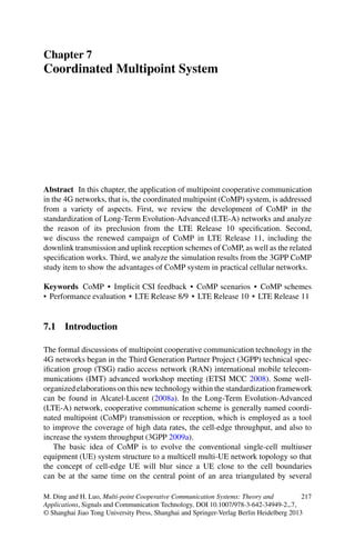
  • 19. 7.3 CoMP Schemes in LTE Release 11 235 BS1 BS2 BS3 JT UE1 UE2 Fig. 7.8 Illustration of a partial JT scheme 11 LTE-A network, two types of downlink CoMP transmission schemes have been identified with high working priority, that is, joint processing (JP) and coordinated scheduling/coordinated beamforming (CS/CB) (3GPP 2011b). 7.3.1.1 Joint Processing In JP CoMP, both data and CSI are shared among multiple points. If time-frequency synchronized transmission (TFST) is operated, that is, a UE data is simultaneously transmitted from multiple points on a time-frequency resource to improve the re- ceived signal quality and/or data throughput, then JP will become joint transmission (JT), which has been discussed in the eighth category of multipoint cooperative communication technology (see Sect. 2.7.8). On the other hand, if non-TFST is allowed, then a UE data will be transmitted from a selected point, possibly with additional muted point(s). This JP scheme degrades to dynamic point selection (DPS) and/or dynamic point blanking (DPB), which has been treated in the sixth category of multipoint cooperative communication technology (see Sect. 2.7.6). It should be noted that DPS and JT schemes can be combined to form a partial JT scheme, in which more than one point, but not all the available points, are selected for JT operation. An illustration of a partial JT scheme is shown in Fig. 7.8, where BS3 is unselected in the JT for UE1. 7.3.1.2 Coordinated Scheduling/Coordinated Beamforming In the second type of downlink CoMP transmission, that is, CS/CB, a UE data is only available at one transmission point but multipoint CSI is exchanged in
  • 20. 236 7 Coordinated Multipoint System BS1 BS2 BS3 JT UE1 Fig. 7.9 Illustration of a hybrid JP and CS/CB scheme the network for interpoint coordination of scheduling and/or beamforming. Such scheme belongs to the seventh category of multipoint cooperative communication technology (see Sect. 2.7.7). Note that if point muting is considered, CS/CB schemes will fall into the fifth category of multipoint cooperative communication technology (see Sect. 2.7.5). In 3GPP (2011b), it also doesn’t preclude the possibility of a hybrid JP and CS/CB scheme, which is essentially an interesting combination of the 5th, 6th, 7th, and 8th multipoint cooperative communication technologies. In this general scheme, some points are denoted as JP points and other points serve as CS/CB points. Interpoint CSI is shared among the JP and CS/CB points, but data only arrives at the JP points. Among the JP points, some points will be activated to perform JT, while the CS/CB points will conduct dynamic or semi-static interference coordination. An illustration of a hybrid JP and CS/CB scheme is shown in Fig. 7.9, where BS1 and BS2 are performing JT for UE1 while BS3 avoids pointing its spatial-domain beams at UE1 as a CB operation. 7.3.2 Uplink CoMP Reception Schemes Similar to the downlink CoMP transmission, uplink CoMP reception also features on JP and CS/CB. The uplink JP reception implies joint reception (JR) of the transmitted signal at multiple points to improve the receive SINR, which belongs to the eighth category of multipoint cooperative communication technology (see Sect. 2.7.8). The uplink CS/CB operation involves multicell UE scheduling, power control, low-interference precoder design, etc. The related schemes have been discussed in Sects. 2.7.5 and 2.7.7.
  • 21. 7.5 Simulation and Analysis 237 7.4 Specification Works In standardization activities, identifying the technical schemes is just the first step. Detailed protocols and necessary information provisions should be carefully specified so that the interested schemes can be put to practical use with both the BS and UE knowing how to conduct the operations. Regarding the downlink CoMP schemes, for scenarios 2–4, inter-BS coordina- tion is obviously needed. Thus, protocols of information exchange over the backhaul links should be designed for BSs. Besides, control signaling should be specified to assist the information acquisition between the BS and UE, such as multicell CSI report from the UE to the BS, enhanced RSs broadcasted from BSs to facilitate the CSI measurement at the UE side, and radio resource control of CoMP schemes configured by the BS. Among the mentioned specification works, the most effort- demanding area is the design of CSI report because it directly impacts the trade-off between system performance and feedback overhead. As have been explained in Sect. 2.6, more CSI generally promises better performance and the problem is that full CSI cannot be obtained at the transmitter side even for the time division duplex (TDD) system. Therefore, to what level and with what contents the CSI shall be provided to the system always arouse hot debates in standardization meetings. As for the uplink CoMP schemes, the situation is less complicated since the UE is only able to perform simple transmission and most of the signal processing burden is transferred to the BS receiver, which can be left to vendor implementations. Nev- ertheless, several specification areas include inter-BS data exchange, enhancement of uplink RSs to increase the RS capacity and improve the RS orthogonality, and low-interference-oriented transmission power decrease at UE due to high reliability of multipoint reception or coordination. 7.5 Simulation and Analysis Large performance gain can be foreseen for the uplink CoMP schemes since any enhanced receiver can achieve performance gains by using advanced signal processing algorithms. Therefore, during the CoMP study item, most simulation efforts were devoted to evaluate the performance of downlink CoMP schemes, where various nonideal assumptions about the BS coordination may offset the theoretical gain promised by the downlink CoMP. In the following, we will review the simulation and analysis results for the downlink CoMP schemes in 3GPP. In phase I of the performance evaluation for CoMP scenarios 1 and 2, about 20 companies provided their simulation results in Samsung (2011). In spite of the fact that tremendous work had already been devoted to the unification of evaluation methodology and calibration of system-level simulators from various companies, so that comparable results could be obtained from multiple sources to double-check the true gain of CoMP schemes in practical systems, it was a bit discouraging to find
  • 22. 238 7 Coordinated Multipoint System that large performance differences still existed in the reported results because the detailed software implementation in each simulator still can be very different among the source companies (see the references in Samsung (2011)). One prominent example of the nontransparent implementation issue is the BS scheduler, which has a significant impact on the distribution of UE throughputs and thus greatly influences the results of cell-edge throughput and the proportional fairness factor of the interested schemes. The baseline simulation parameters for phase I evaluation can be found in 3GPP (2010, 2011b), and the performance metrics are cell average spectral efficiency in bps/Hz/cell and 5% point cell-edge UE spectral efficiency in bps/Hz/user (3GPP 2011b). From practical considerations, it is assumed that every UE reports CSI based on the assumption of SU MIMO transmission. For CoMP scenario 1 illustrated in Fig. 7.2, simulations were conducted for fre- quency division duplex (FDD)/time division duplex (TDD) downlink with closely spaced cross-polarized antenna deployment and full-buffer (FB) traffic for the 3GPP case 1 and ITU channel models. For BS and UE equipped with four and two antennas, respectively, the JT MU-MIMO scheme was shown to achieve an average performance gain about 20–30% in terms of cell-edge UE spectral efficiency as well as some moderate gains in cell average spectral efficiency compared with the single- cell MU-MIMO scheme. On the other hand, the performance gain offered by CS/CB MU MIMO seemed to be rather limited, less than 5% for FDD and around 10% for TDD in terms of cell-edge UE spectral efficiency. For CoMP scenario 2 illustrated in Fig. 7.3, similar simulation assumptions were adopted as those for CoMP scenario 1. As for the set of cooperating cells, JT in a nine-cell coordination area was considered as the baseline. In addition, uniform linear array (ULA) was considered as an alternative antenna configuration. Similar observations can be drawn for JT and CS/CB when BS and UE are, respectively, equipped with four and two antennas (3GPP 2011b). Besides, a notable finding is that increasing the BS coordination area, that is, conducting CoMP operation among more than nine cells, has a positive effect on CS/CB while it is not helpful for JT because JT MU-MIMO across too many cells will have to sacrifice considerable performance gain in exchange for complexity reduction in practical systems. In phase II of the performance evaluation for CoMP scenarios 3 and 4, the system-level simulation parameters for the heterogeneous networks are specified in 3GPP (2011b) and a total of 25 companies presented their simulation results. In addition to the traffic model used in CoMP study item phase I, a non-full-buffer model was considered in phase II for simulations of dynamic traffic in hot spots. For FDD systems and FB traffic models, both CS/CB and JP schemes can achieve 25–30% gain in cell-edge UE spectral efficiency compared with a baseline scheme without interference management. Note that the performance gains become even larger for non-full-traffic models because idle resources in a low- or medium-loaded system can be utilized by the network to operate non-time-frequency-synchronized transmission or reception (TFSTR) CoMP schemes, that is, the third, fourth, fifth, and sixth categories of multipoint cooperative communication technologies (see Sect. 2.7).
  • 23. References 239 To sum up, from the performance evaluation results in the 3GPP CoMP study item, it can be concluded that both the downlink and uplink CoMP schemes can offer performance benefits in all defined scenarios. But it is also found that performance of CoMP schemes with spatial information exchange is sensitive to the delay between two transmission points (3GPP 2011b). Therefore, aspects related to the delay issue, such as limited-bit CSI feedback and/or nonideal backhaul conditions, should be further investigated. 7.6 Conclusion After several years of study in academic communities, the seventh and eighth categories of multipoint cooperative communication technologies were considered to be applied in practical cellular networks, for example, in the LTE Release 10 system. The applications are generally called CoMP transmission or reception. Although the CoMP function is failed to be adopted by the LTE Release 10 specifications due to some incompatible CSI feedback designs with the single- cell MIMO framework, it has eventually come back for the LTE Release 11 standardization. Several interested CoMP schemes have been identified as JT/JR or CS/CB. The corresponding specification works are related to aspects such as backhaul communication protocols, control signaling provision, and multipoint CSI feedback design. The performance evaluation results of various CoMP schemes show that considerable gains can be expected from CoMP, but the multipoint delay issue should be further investigated for practical applications. References 3GPP (2006) TR 25.814 V7.1.0: physical layer aspects for evolved Universal Terrestrial Radio Access (UTRA) (Release 7). http://www.3gpp.org/ftp/Specs/archive/25 series/25.814/25814- 710.zip. Accessed Oct 2006 3GPP (2008) TS 25.213 V8.0.0: physical layer procedures (Release 8). http://www.3gpp.org/ftp/ Specs/archive/25 series/25.213/25213-800.zip. Accessed Mar 2008 3GPP (2009a) TR 36.814 V1.0.0: further advancements for E-UTRA: physical layer aspects. http:// www.3gpp.org/ftp/Specs/archive/36 series/36.814/36814-100.zip. Accessed Feb 2009 3GPP (2009b) TS 25.213 V9.0.0: physical layer procedures (Release 9). http://www.3gpp.org/ftp/ Specs/archive/25 series/25.213/25213-900.zip. Accessed Sept 2009 3GPP (2010) TR 36.814: further advancements for E-UTRA, physical layer aspects. http://www. 3gpp.org/ftp/Specs/archive/36 series/36.814/36814-900.zip. Accessed Mar 2010 3GPP (2011a) TS 36.213 V10.1.0: physical layer procedures (Release 10). http://www.3gpp.org/ ftp/Specs/archive/36 series/36.213/36213-a10.zip. Accessed Mar 2011 3GPP (2011b) TR 36.819 V11.1.0: coordinated multi-point operation for LTE physical layer aspects (Release 11). http://www.3gpp.org/ftp/Specs/archive/36 series/36.819/36819-b10.zip. Accessed Dec 2011
  • 24. 240 7 Coordinated Multipoint System Alcatel-Lucent (2008a) R1-082812: collaborative MIMO for LTE-A downlink. In: 3GPP TSG RAN WG1 meeting #54, Jeju, Korea, 18–22 Aug 2008. http://www.3gpp.org/ftp/tsg ran/WG1 RL1/TSGR1 54/Docs/R1-082812.zip Alcatel-Lucent (2008b) R1-084141: UE PMI feedback signalling for user pairing/coordination. In: 3GPP TSG RAN WG1 #55, Prague, Czech Republic, 10–14 Nov 2008. http://www.3gpp.org/ ftp/tsg ran/WG1 RL1/TSGR1 55/docs/R1-084141.zip CATT (2008a) R1-084290: proposal of multiple sites coordination for LTE-A TDD. In: 3GPP TSG RAN WG1 meeting #55, Prague, Czech Republic, 10–14 Nov 2008. http://www.3gpp.org/ftp/ tsg ran/WG1 RL1/TSGR1 55/docs/R1-084290.zip CATT (2008b) R1-083630: a technique to enhance the cell edge performance. In: 3GPP TSG RAN WG1 #54bis, Prague, Czech Republic, September 29–October 3 2008. http://www.3gpp. org/ftp/tsg ran/WG1 RL1/TSGR1 54b/Docs/R1-083630.zip Ericsson (2008) R1-084377: downlink coordinated transmission–impact on specification. In: 3GPP TSG-RAN WG1 #55, Prague, Czech Republic, 10–14 Nov 2008. http://www.3gpp.org/ftp/tsg ran/WG1 RL1/TSGR1 55/docs/R1-084377.zip Ericsson (2009) R1-092019: summary from email discussion on calibration step1C2. In: 3GPP TSG RAN1 meeting #57, San Francisco, 4–8 May 2009. http://www.3gpp.org/ftp/tsg ran/wg1 rl1/TSGR1 57/Docs/R1-092019.zip Ericsson, ST-Ericsson (2011) R1-110452: deployment and backhaul constraints for CoMP. In: 3GPP TSG-RAN1#63bis meeting, Dublin, Ireland, 17–21 Jan 2011. http://www.3gpp.org/ftp/ tsg ran/WG1 RL1/TSGR1 63b/Docs/R1-110452.zip Ericsson et al (2011) R1-112852: proposal for DL CoMP standardization impact. In: 3GPP TSG- RAN WG1 meeting #66, Athens, Greece, 22–26 Aug 2011. http://www.3gpp.org/ftp/tsg ran/ wg1 rl1/TSGR1 66/Docs/R1-112852.zip ETRI (2008a) R1-082896: coordinated multi-cell transmission for LTE-advanced downlink. In: 3GPP TSG-RAN WG1 #54, Jeju, South Korea, 18–22 August 2008. http://www.3gpp.org/ftp/ tsg ran/WG1 RL1/TSGR1 54/Docs/R1-082896.zip ETRI (2008b) R1-084144: per-cell precoding methods for downlink joint processing CoMP. In: 3GPP TSG RAN WG1#55, Prague, Czech Republic, 10–14 Nov 2008. http://www.3gpp.org/ ftp/tsg ran/WG1 RL1/TSGR1 55/docs/R1-084144.zip ETSI MCC (2010a) Report of 3GPP TSG RAN meeting #47. In: 3GPP TSG RAN #47, Vienna, Austria, 16–19 Mar 2010. http://www.3gpp.org/ftp/tsg ran/TSG RAN/TSGR 47/Report/RP- 100648.zip ETSI MCC (2010b) Report of 3GPP TSG RAN meeting #48. In: 3GPP TSG RAN meeting #48, Seoul, Korea, 1–4 June 2010. http://www.3gpp.org/ftp/tsg ran/TSG RAN/TSGR 48/Report/ RP-100969.zip ETSI MCC (2010c) Report of 3GPP TSG RAN meeting #49. In: 3GPP TSG RAN meeting #49, San Antonio, 14–17 Sept 2010. http://www.3gpp.org/ftp/tsg ran/TSG RAN/TSGR 49/Report/ RP-101373.zip ETSI MCC (2011) Report of 3GPP TSG RAN meeting #50. In: 3GPP TSG RAN meeting #50, Istanbul, Turkey, 7–12 Dec 2010. http://www.3gpp.org/ftp/tsg ran/TSG RAN/TSGR 50/ Report/RP-110361.zip ETSI Mobile Competence Centre (MCC) (2008) REV-080060: report of the 3GPP TSG RAN IMT advanced workshop. In: 3GPP TSG RAN IMT advanced workshop, Shenzhen, China, 7–8 Apr 2008. http://www.3gpp.org/ftp/workshop/2008-04-07 RAN IMT Advanced/Docs/REV- 080060.zip Gesbert D, Hanly S, Huang H, Shamai S, Simeone O, Wei Y (2010) Multi-cell MIMO cooperative networks: a new look at interference. IEEE J Sel Areas Commun 28(9):1380–1408 Hitachi (2008) R1-083689: proposal of inter cell interference coordination scheme. In: 3GPP TSG RAN WG1 #54bis, Prague, Czech Republic, September 29–October 3, 2008. http://www.3gpp. org/ftp/tsg ran/WG1 RL1/TSGR1 54b/Docs/R1-083689.zip Huawei (2008) R1-084352: DL coordinated beam switching for interference management in LTE- advanced. In: 3GPP TSG RAN WG1#55, Prague, Czech Republic, 10–14 Nov 2008. http:// www.3gpp.org/ftp/tsg ran/WG1 RL1/TSGR1 55/docs/R1-084352.zip
  • 25. References 241 Huawei et al (2011) R1-112829; way forward on CoMP performance gains. In: 3GPP TSG-RAN WG1 meeting #66, Athens, Greece, 22–26 Aug 2011. http://www.3gpp.org/ftp/tsg ran/wg1 rl1/TSGR1 66/Docs/R1-112829.zip ITU-R (1997) Recommendation ITU-R M.1225: guidelines for evaluation of radio transmis- sion technologies for IMT-2000. http://www.itu.int/dms pubrec/itu-r/rec/m/R-REC-M.1225- 0-199702-I!!PDF-E.pdf. Accessed 1997 LGE (2008) R1-084202: multi-layered rate control for CoMP in LTE-advanced. In: 3GPP TSG RAN WG1#55, Prague, Czech Republic, 10–14 Nov 2008. http://www.3gpp.org/ftp/tsg ran/ WG1 RL1/TSGR1 55/docs/R1-084202.zip MCC Support (2008a) Final report of 3GPP TSG RAN WG1 #54 v1.0.0. In: 3GPP TSG RAN WG1 #54, Jeju Island, South Korea, 18–22 Aug 2008. http://www.3gpp.org/ftp/tsg ran/WG1 RL1/TSGR1 54/Report/Final ReportWG1#54 v100.zip MCC Support (2008b) Draft report of 3GPP TSG RAN WG1 #54b v0.2.0. In: 3GPP TSG RAN WG1 #54b, Czech Republic, September 29–October 3, 2008. http://www.3gpp.org/ftp/tsg ran/ WG1 RL1/TSGR1 54b/Report/Draft ReportWG1#54b v020.zip MCC Support (2008c) Final report of 3GPP TSG RAN WG1 #55 v1.0.0. In: 3GPP TSG RAN WG1 #55, Czech Republic, 10–14 Nov 2008. http://www.3gpp.org/ftp/tsg ran/WG1 RL1/ TSGR1 55/Report/Final ReportWG1#55 v100.zip MCC Support (2009a) Final report of 3GPP TSG RAN WG1 #55bis v3.0.0. In: 3GPP TSG RAN WG1 #55bis, Ljubljana, Slovenia, 12–16 Jan 2009. http://www.3gpp.org/ftp/tsg ran/WG1 RL1/TSGR1 55b/Report/Final ReportWG1#55bis v300.zip MCC Support (2009b) Final report of 3GPP TSG RAN WG1 #56 v1.0.0. In: 3GPP TSG RAN WG1 #56, Athens, Greece, 9–13 Feb 2009. http://www.3gpp.org/ftp/tsg ran/WG1 RL1/ TSGR1 56/Report/Final ReportWG1#56 v100.zip MCC Support (2009c) Final report of 3GPP TSG RAN WG1 #56bis v2.0.0. In: 3GPP TSG RAN WG1 #56bis, Seoul, South Korea, 23–27 Mar 2009. http://www.3gpp.org/ftp/tsg ran/WG1 RL1/TSGR1 56b/Report/Final ReportWG1#56b v200.zip MCC Support (2009d) Final report of 3GPP TSG RAN WG1 #57 v1.0.0. In: 3GPP TSG RAN WG1 #57, San Francisco, 4–8 May 2009. http://www.3gpp.org/ftp/tsg ran/WG1 RL1/TSGR1 57/Report/Final ReportWG1#57 v100.zip MCC Support (2009e) Final report of 3GPP TSG RAN WG1 #57bis v1.0.0. In: 3GPP TSG RAN WG1 #57bis, Los Angeles, June 29–July 3 2009. http://www.3gpp.org/ftp/tsg ran/WG1 RL1/ TSGR1 57b/Report/Final ReportWG1#57b v100.zip MCC Support (2009f) Final report of 3GPP TSG RAN WG1 #58 v1.0.0. In: 3GPP TSG RAN WG1 #58, Shenzhen, China, 24–28 Aug 2009. http://www.3gpp.org/ftp/tsg ran/WG1 RL1/TSGR1 58/Report/Final ReportWG1#58 v100.zip MCC Support (2009g) Final report of 3GPP TSG RAN WG1 #58bis v1.0.0. In: 3GPP TSG RAN WG1 #58bis, Miyazaki, Japan, 12–16 Oct 2009. http://www.3gpp.org/ftp/tsg ran/WG1 RL1/ TSGR1 58b/Report/Final ReportWG1#58b v100.zip MCC Support (2009h) Final report of 3GPP TSG RAN WG1 #59 v1.0.0. In: 3GPP TSG RAN WG1 #59, Jeju, South Korea, 9–13 Nov 2009. http://www.3gpp.org/ftp/tsg ran/WG1 RL1/ TSGR1 59/Report/Final ReportWG1#59 v100.zip MCC Support (2010a) Draft report of 3GPP TSG RAN WG1 #59bis v0.1.0. In: 3GPP TSG RAN WG1 #59bis, Valencia, Spain, 18–22 Jan 2010. http://www.3gpp.org/ftp/tsg ran/WG1 RL1/ TSGR1 59b/Report/Draft ReportWG1#59b v020.zip MCC Support (2010b) Final report of 3GPP TSG RAN WG1 #60 v1.0.0. In: 3GPP TSG RAN WG1 #60, California, 22–26 Feb 2010. http://www.3gpp.org/ftp/tsg ran/WG1 RL1/TSGR1 60/Report/R1-101711.zip MCC Support (2010c) Final report of 3GPP TSG RAN WG1 #60bis v1.0.0. In: 3GPP TSG RAN WG1 #60bis, Beijing, China, 12–16 Apr 2010. http://www.3gpp.org/ftp/tsg ran/WG1 RL1/ TSGR1 60b/Report/R1-102601.zip MCC Support (2010d) Final report of 3GPP TSG RAN WG1 #61 v3.0.0. In: 3GPP TSG RAN WG1 #61, Montreal, Canada, 10–14 May 2010. http://www.3gpp.org/ftp/tsg ran/WG1 RL1/ TSGR1 61/Report/Final ReportWG1#61 v300.zip
  • 26. 242 7 Coordinated Multipoint System MCC Support (2010e) Draft report of 3GPP TSG RAN WG1 #62 v0.1.0. In: 3GPP TSG RAN WG1 #62, Madrid, Spain, 23–27 Aug 2010. http://www.3gpp.org/ftp/tsg ran/WG1 RL1/ TSGR1 62/Report/Draft ReportWG1#62 v010.zip MCC Support (2010f) Draft report of 3GPP TSG RAN WG1 #62bis v0.1.0. In: 3GPP TSG RAN WG1 #62bis, Xian, China, 11–15 Oct 2010. http://www.3gpp.org/ftp/tsg ran/WG1 RL1/ TSGR1 62b/Report/Draft ReportWG1#62b v010.zip MCC Support (2010g) Final report of 3GPP TSG RAN WG1 #63 v1.0.0. In: 3GPP TSG RAN WG1 #63, Florida, 15–19 Nov 2010. http://www.3gpp.org/ftp/tsg ran/WG1 RL1/TSGR1 63/ Report/Final ReportWG1#63 v100.zip MCC Support (2011a) Final report of 3GPP TSG RAN WG1 #63bis v1.0.0. In: 3GPP TSG RAN WG1 #63bis, Dublin, Ireland, 17–21 Jan 2011. http://www.3gpp.org/ftp/tsg ran/WG1 RL1/ TSGR1 63b/Report/Final ReportWG1#63b v100.zip MCC Support (2011b) Final report of 3GPP TSG RAN WG1 #64 v1.3.0. In: 3GPP TSG RAN WG1 #64, Taipei, Taiwan, 21–25 Feb 2011. http://www.3gpp.org/ftp/tsg ran/WG1 RL1/ TSGR1 64/Report/Final ReportWG1#64 v130.zip MCC Support (2011c) Draft report of 3GPP TSG RAN WG1 #65 v1.0.0. In: 3GPP TSG RAN WG1 #65, Barcelona, Spain, 9–13 May 2011. http://www.3gpp.org/ftp/tsg ran/WG1 RL1/ TSGR1 65/Report/Final ReportWG1#65 v100.zip MCC Support (2011d) Final report of 3GPP TSG RAN WG1 #66 v1.0.0. In: 3GPP TSG RAN WG1 #66, Athens, Greece, 22–26 Aug 2011. http://www.3gpp.org/ftp/tsg ran/WG1 RL1/ TSGR1 66/Report/Final ReportWG1#66 v100.zip Mitsubishi (2008) R1-084482: low-complexity precoding for LTE-A collaborative MIMO: a signal leakage approach. In: 3GPP TSG RAN WG1#55, Prague, Czech Republic, 10–14 Nov 2008. http://www.3gpp.org/ftp/tsg ran/WG1 RL1/TSGR1 55/docs/R1-084482.zip Motorola (2008) R1-084407: coordinated multi-point transmission – exploring possible system operations and UE support. In: 3GPP TSG RAN WG1#55, Prague, Czech Republic, 10–14 Nov 2008. http://www.3gpp.org/ftp/tsg ran/WG1 RL1/TSGR1 55/docs/R1-084407.zip Nokia (2008) R1-084322: scalable CoMP solutions for LTE advanced. In: 3GPP TSG RAN WG1#55, Prague, Czech Republic, 10–14 Nov 2008. http://www.3gpp.org/ftp/tsg ran/WG1 RL1/TSGR1 55/docs/R1-084322.zip Nortel (2008a) R1-084464: cell clustering for CoMP transmission/reception. In: 3GPP TSG-RAN WG1 #55, Prague, Czech Republic, 10–14 Nov 2008. http://www.3gpp.org/ftp/tsg ran/WG1 RL1/TSGR1 55/docs/R1-084464.zip Nortel (2008b) R1-084465: discussion and link level simulation results on LTE-A downlink multi- site MIMO cooperation. In: 3GPP TSG RAN WG1#55, Prague, Czech Republic, 10–14 Nov 2008. http://www.3gpp.org/ftp/tsg ran/WG1 RL1/TSGR1 55/docs/R1-084465.zip NTT DoCoMo (2008) R1-084252: views on coordinated multipoint transmission/reception in LTE-advanced. In: 3GPP TSG RAN WG1#55, Prague, Czech Republic, 10–14 Nov 2008. http://www.3gpp.org/ftp/tsg ran/WG1 RL1/TSGR1 55/docs/R1-084252.zip NTT DOCOMO (2011) R1-110598: CoMP simulation assumptions. In: 3GPP TSG RAN1 #63bis, Dublin, Ireland, 17–21 Jan 2011. http://www.3gpp.org/ftp/tsg ran/WG1 RL1/TSGR1 63b/Docs/R1-110598.zip NTT DOCOMO et al (2010) R1-101599: way forward for CoMP in release 10. In: 3GPP TSG RAN WG1 #60, California, 22–26 Feb 2010. http://www.3gpp.org/ftp/tsg ran/wg1 rl1/TSGR1 60/ Docs/R1-101599.zip Orange et al (2011) R1-110546: views on CoMP evaluation methodology. In: 3GPP TSG- RAN1#63bis meeting, Dublin, Ireland, 17–21 Jan 2011. http://www.3gpp.org/ftp/tsg ran/ WG1 RL1/TSGR1 63b/Docs/R1-110546.zip Philips (2008a) R1-084100: multi-cell co-operative beamforming: operation and performance. In: 3GPP TSG RAN WG1#55, Prague, Czech Republic, 10–14 Nov 2008. http://www.3gpp.org/ ftp/tsg ran/WG1 RL1/TSGR1 55/docs/R1-084100.zip Philips (2008b) R1-084099: interference management for LTE-advanced. In: 3GPP TSG RAN WG1#55, Prague, Czech Republic, 10–14 Nov 2008. http://www.3gpp.org/ftp/tsg ran/WG1 RL1/TSGR1 55/docs/R1-084099.zip
  • 27. References 243 Qualcomm (2008) R1-084400: coordinated multi-point downlink transmission in LTE-advanced. In: 3GPP TSG RAN WG1#55, Prague, Czech Republic, 10–14 Nov 2008. http://www.3gpp. org/ftp/tsg ran/WG1 RL1/TSGR1 55/docs/R1-084400.zip Samsung (2008) R1-084173: inter-cell interference mitigation through limited coordination. In: 3GPP TSG RAN WG1#55, Prague, Czech Republic, 10–14 Nov 2008. http://www.3gpp.org/ ftp/tsg ran/WG1 RL1/TSGR1 55/docs/R1-084173.zip Samsung (2010a) RP-101425: revised SID proposal: coordinated multi-point operation for LTE. In: 3GPP TSG RAN#50, Istanbul, Turkey, 7–10 Dec 2010. http://www.3gpp.org/ftp/tsg ran/ TSG RAN/TSGR 50/Docs/RP-101425.zip Samsung (2010b) RP-101425: revised SID proposal: coordinated multi-point operation for LTE. In: 3GPP TSG RAN#50 meeting, Istanbul, Turkey, 7–10 Dec 2010. http://www.3gpp.org/ftp/ tsg ran/TSG RAN/TSGR 50/Docs/RP-101425.zip Samsung (2011) R1-111944: RAN1 phase 1 CoMP results. In: 3GPP TSG RAN WG1 Meeting #65, Barcelona, Spain, 9–13 May 2011. http://www.3gpp.org/ftp/tsg ran/WG1 RL1/TSGR1 65/Docs/R1-111944.zip Samsung et al (2010) RP-100370: new study item proposal: coordinated multi-point operation for LTE. In: TSG RAN meeting #47, Vienna, Austria, 16–19 Mar 2010. http://www.3gpp.org/ftp/ tsg ran/tsg ran/TSGR 47/Docs/RP-100370.zip Texas Instruments (2011) R1-111342: Rel.11 DL MIMO enhancements for single-cell with RRHs. In: 3GPP TSG RAN WG1 65, Barcelona, Spain, 9–13 May 2011. http://www.3gpp.org/ftp/tsg ran/WG1 RL1/TSGR1 65/Docs/R1-111342.zip TI (2008) R1-084444: aspects of cooperative MIMO for advanced E-UTRA. In: 3GPP TSG RAN WG1#55, Prague, Czech Republic, 10–14 Nov 2008. http://www.3gpp.org/ftp/tsg ran/WG1 RL1/TSGR1 55/docs/R1-084444.zip Vodafone et al (2010) R1-100764: proposal for intra-eNB/inter-site eNB CoMP. In: 3GPP TSG RAN WG1 meeting #59bis, Valencia, Spain, 18–22 Jan 2010. http://www.3gpp.org/ftp/tsg ran/WG1 RL1/TSGR1 59b/Docs/R1-100764.zip ZTE (2008a) R1-082847: on consideration for CoMP in LTE-A. In: 3GPP TSG-RAN WG1 #54, Jeju, South Korea, 18–22 Aug 2008. http://www.3gpp.org/ftp/tsg ran/WG1 RL1/TSGR1 54/ Docs/R1-082847.zip ZTE (2008b) R1-083611: consideration on COMP antenna port mapping in LTE-A. In: 3GPP TSG RAN WG1 #54bis, Prague, Czech Republic, September 29–October 3 2008. http://www.3gpp. org/ftp/tsg ran/WG1 RL1/TSGR1 54b/Docs/R1-083611.zip ZTE (2008c) R1-084115: downlink CoMP transmitting scheme based on beamforming. In: 3GPP TSG RAN WG1#55, Prague, Czech Republic, 10–14 Nov 2008. http://www.3gpp.org/ftp/tsg ran/WG1 RL1/TSGR1 55/docs/R1-084115.zip