Assembly of the components (Crank shaft, Connecting rod, Gudgeon pin and Piston) by
using different manufacturing processes from the material generated as a scrap during
manufacturing of different products through various processes.
1. ADVANCED MANUFACTURINGPROCESS
Complex Problem
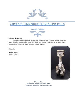
Problem Statement:
Assembly of the components (Crank shaft, Connecting rod, Gudgeon pin and Piston) by
using different manufacturing processes from the material generated as a scrap during
manufacturing of different products through various processes.
Written By:
Sohail Akbar
Mechanical Engineer
JULY 8, 2020
MECHANICAL ENGINEERING DEPARTMENT
University of Enginnering and Technology, Taxila
2. Crank Shaft:
A crankshaft is an important part of an engine. It is the heart of an automotive vehicular
system. In an internal combustion engine crankshaft converts the linear motion of the piston in to
rotary motion of the flywheel. This converted rotary motion is used to drive automobile or any
other device. Power from the burnt gases in the combustion chamber is used through the piston,
piston pin and connecting rod. A crankshaft has a very wide range of applications from one small
single cylinder engine to very large multi cylinder engines.
Crankshaft is a large component which is complex in geometry. As the crankshaft
experiences a large no of load cycles during its service life, fatigue performance and durability of
this component has to be considered in the design process.
Material: Steel is the material of crank shaft.
Manufacturing Process:
Forging process is used in manufacturing of crank shaft. Forging is nothing but shaping of
metal by plastic deformation. There are three typical stages of crankshaft forging.
1 | Page
3. In forging deformation is induced in each stage to ensure metal flow in to the die cavity in
both top and bottom dies. The work piece moves in a particular direction in each stage with a
specific velocity. Metal flow pattern fills the complete die cavity as shown in the following chart
to produce a sound forging. This process is followed by no of post processes like machining, heat
treatment also.
Surface Treatment:
Gas nit riding hardens the surface through the supply of nitrogen. In the nitro carburizing
process, the crankshafts are treated with ammonia, nitrogen, carbon dioxide and cracked gas before
being quenched in the oil bath. Deep rolling of the fillets, which is performed as a mechanical
transformation procedure, also increases the fatigue strength. These multifaceted technologies
enable us to meet almost all customer requirements in terms of increasing performance and
reducing wear.
Inspection:
Check the crankshaft journal and crank pin surface for wear and damage.
Check the contact surface of the oil seal for excessive wear or damage.
Check the oil port for clogging
Measure the crankshaft using a dial gauge.
Slowly rotate the crankshaft to measure the runout.
Replace the crankshaft if the crankshaft runout exceeds the limit.
2 | Page
4. Connecting Rod:
In a reciprocating piston engine, the connecting rod connects the piston to the crank or
crankshaft. In modern automotive internal combustion engines, the connecting rods are usually
made of aluminum for lightness and the ability to absorb high impact at the expense of durability.
They are not rigidly fixed at either end, so that the angle between the connecting rod and the piston
can change as the rod moves up and down and rotates around the crankshaft. Its primary function
the push and pull from the piston pin to the crank pin and thus converts the reciprocating motion
of the piston into rotary motion of the crank.
Material: Aluminum is the material for connecting rod
Manufacturing Process:
Connecting Rod is made by using casting process. Casting is a manufacturing process in
which a liquid material is usually poured into a mold, which contains a hollow cavity of the desired
shape, and then allowed to solidify. The solidified part is also known as a casting, which is ejected
or broken out of the mold to complete the process.
Here we use the process of die casting. Die casting is a versatile process for producing
engineered metal parts by forcing molten metal under high pressure into reusable steel molds.
These molds, called dies, can be designed to produce complex shapes with a high degree of
accuracy and repeatability. Parts can be sharply defined, with smooth or textured surfaces, and are
suitable for a wide variety of attractive and serviceable finishes.
3 | Page
5. Shrinkage Table for Die-Casting Alloys:
Dimensions of cross section of connecting rod:
Thickness of flange & web of the section = 9mm Approx.
Length of connecting rod = 117.2mm
Width of section B = 4t = 36mm
Height of section H = 5t = 45mm
Height at the big end (crank end) = H2 = 56.25 mm
Height at the small end (piston end) = 40.5mm
Design Aspects of Die Casting:
Since the metallic mold of a die casting expands when it is filled with a molten metal and
then both the casting and the mold shrinks during cooling the shrinkage allowances taken
in the die mold design are smaller than those in the Sand casting.
Parts of 0.05 lb. (20 g) to 75 lb. (34 kg) may be cast.
The section thickness of permanent mold casting may vary in the range 0.02” - 0.5” (0.5-
12 mm).
The dimensional tolerances are 0.01-0.03” (0.25-0.75 mm) depending on the casting
section thickness.
Allowances of 0.004-0.01” (0.1-0.25 mm) are taken for the dimensions crossing the parting
line of the mold.
The draft angle is commonly about 1%.
Physical Properties of Aluminum:
4 | Page
Physical Properties Metric English
Hardness, Vickers 107 107
Ultimate Tensile
Strength
310 MPa 45000 psi
Tensile Yield Strength 276 MPa 40000 psi
Elongation at Break 12 % 12 %
Castingalloy Shrinkage ( % )
Aluminum 0.5 – 0.7
Magnesium 0.8 – 1.2
Brass 0.7 – 1.2
Led 0.3 – 0.6
6. Surface treatment methods of aluminum:
Surface Treatment of Aluminum is required to improve surface properties of final products,
such as wear resistance, corrosion resistance, reflectivity etc.
Typical aluminum surface treatment methods include anodic oxide coating,
coloration, coating, mechanical surface treatment, chemical film coating, bright anodic
oxide coating (gloss treatment), enamel coating, and plating. In addition, new technologies have
been developed including ion plating and sputtering.
Inspection of connecting rod:
Always inspect any connecting rod for bend and twist. A bend in the rod beam results in
the centerline of the big-end bore being out of alignment with the center of the wrist pin bore. A
twist in the beam throws the big-end bore out-of-plane with the small end.
Gudgeon Pin
The gudgeon pin is typically a short hollow rod made of a material of high strength
and hardness that may be physically separated from both the connecting rod and piston. Gudgeon
pin connects the connecting rod with the piston head. Usually a pin of this sort is used as to avoid
any other axis of motion of the piston which can be induced when any other kind of link is used
as the piston has to move in a rectilinear to and fro motion.
Material: We use titanium for Gudgeon pin.
5 | Page
7. Mechanical Properties of Titanium:
Manufacturing Process:
Gudgeon pin can be made by using machining process. In this process we take a rod of
titanium and apply turning process on it after that we produce a hole in it and enlarge this hole by
boring at required dimensions. For the finishing other processes can apply on the work piece like
lapping polishing and debarring etc. Titanium aluminum nitride (TiAlN) coated carbide is usually
the best choice for machining titanium. Out of the handful of basic cutting tool coating types,
TiAlN is clearly the best at maintaining its integrity and properties as the temperature in the cut gets
hot.
Dimensions of Gudgeon Pin:
l1=length of the piston pin in the bush of the small end of the connecting rod in mm = 25.65mm
do =outside dia of the piston pin = 15.16mm
di =0.6 do = 9.1mm
Length between the supports l2 = 41.325mm
Surface Treatment of Titanium pin
Titanium Anodizing:
Titanium anodizing is typically used for improving strength by increasing the thickness of
the oxide layer on the metal’s surface. Qualities include enhanced friction performance, anti-
galling, increased wear resistance and little-to-no dimensional change (the primary benefit).
Anodizing is a preferred choice in the metal finishing of products. By adjusting the oxide
level of the metal’s surface, the spectrum of light is changed, altering the perceived color. This
delivers the advantages of hardening and coloring, without changing titanium’s mechanical
6 | Page
Properties Metric Imperial
Tensile strength 220 MPa 31900 psi
Modulus of elasticity 116 GPa 16800 ksi
Shear modulus 43.0 GPa 6240 ksi
Hardness, Brinell 70 70
8. properties. The end result also provides a lasting color and allows easy identification and
organization of parts within complex designs (as with planes). The sanitary, additive-free finish
allows the alloy to retain its high resistance to corrosion and heat.
Inspection of Gudgeon Pin:
Check the piston pin fit in the piston pin hole. Replace any defective piston and pin
assembly that is defective. The piston pin must be smoothly pressed by hand into the pin hole (at
room temperature).
For the inspection we make the cylinder slightly larger than the piston pin hole, open from
both ends from which pin can pass easily. So if the pin passed easily then this is correct design if
it cannot pass then it is rejected.
Piston
A piston is a component of reciprocating engines, reciprocating pumps, gas
compressors and pneumatic cylinders, among other similar mechanisms. Its purpose is to transfer
force from expanding gas in the cylinder to the crankshaft via a piston rod and/or connecting rod.
A piston is a moving disk enclosed in a cylinder which is made gas-tight by piston rings. The disk
moves inside the cylinder as a liquid or gas inside the cylinder expands and contracts. A piston aids
in the transformation of heat energy into mechanical work and vice versa.
Material: Cast Aluminum Alloy
7 | Page
9. Manufacturing Process:
The Rod:
The piston begins as a long solid aluminum rod. The reason aluminum is used is that it's
lightweight, rust-proof, and easy to cut. A saw then cuts the rod into smaller pieces at varied
lengths called slugs.
The Punch:
A punch press and dye are pre-heated while the slug moves through an oven, heating it
to the same temperature as the punch press. The slug is then removed from the oven, and placed
into the punch. The press applies 2,000 tons of pressure onto the slug, forging it into the basic
shape of a piston. This process generates a lot of heat, so the piston must be air cooled for one
hour.
The Oven:
After the forgings cool down, they go through an oven twice more. The first time is at a
higher temperature, to strengthen the metal. The second time is at a lower temperature to stabilize
it.
The Lathe:
A lathe is then used to cut excess metal from the basic form of the piston, taking it closer
to its finished shape. Tiny holes are then drilled into the sides, to create the oil passages for the
piston. The same lathe then impresses three rings into the top of the piston. These rings, or
grooves, help the piston glide, and allow it to form an air-tight seal.
The Wrist Pin Holes:
A large hole is then drilled through both sides of the piston. This is where the wrist pin
will go, which is used to attach the piston to the connecting rod during engine assembly.
The Milling Machine:
A milling machine then shaves up to a couple of centimeters off of each side of the piston
where the large holes were drilled for the wrist pin insertion. This is to reduce the overall weight
of the piston.
Finishing the Job:
Another lathe shaves a few more millimeters off of the top, allowing the piston to expand
when heat builds up inside of it. Then a machine engraves model and production information. A
human worker then smooth out the sharp edges of the piston created during production. The
holes created for the wrist pin are then put through a machine which smooths them, allowing the
wrist pin to fit comfortably. Finally, the pistons sprayed by hot, deionized water, removing any
8 | Page
10. lubricant or oil gathered through the manufacturing process. After they're dry, they're ready for
use.
Dimension of Piston:
Outer Diameter of Piston = 56mm
Height of Piston = 58mm
Displacement of Engine = 149.5CC
Diameter of Piston Pin Hole = 16mm
Aluminum Alloy Characteristics:
Very good strength and hardness.
Good stiffness and strength-to-weight ratio.
Excellent EMI and RFI shielding properties.
Excellent thermal conductivity.
Surface treatment of Piston:
Molybdenum Shot:
A technique, where particles of molybdenum are being shot by compressed air to the
piston’s surface. The technique used earlier was to apply molybdenum coating on the surface by
using a binder. However, after the treatment because of the film’s thickness there was a change in
the dimensions and because of the abrasion the long-term efficiency couldn’t be preserved. In the
case of molybdenum blast binder is not used at all and there is no change in size caused by the
film’s thickness. Furthermore, there is no abrasion between the piston and the cylinder. This
means, that low sliding friction can be maintained for a long period of time. We highly recommend
the piston’s double treatment. It eases the break-in of the product and allows us to use it for long
time with good efficiency.
Inspection of Piston:
Check the followingwhiledoingpiston inspection:
Crown top surface-for burning and cracking damage
Top ring groove & side wall - for crack / deformation and wear
Other ring grooves - for distortion / wear
Cooling passage - for scaling / chocking
Skirt - for wear / rubbing marks
Wear ring / rubbing ring for scuffing
9 | Page