
Recommended
More Related Content
What's hot
What's hot (20)
Similar to Steering System.pdf
Similar to Steering System.pdf (20)
Recently uploaded
Recently uploaded (20)
Steering System.pdf
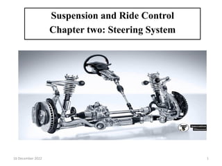
- 1. Suspension and Ride Control Chapter two: Steering System 16 December 2022 1
- 2. Steering System Primarily the steering system allow the driver to control the direction of vehicle travel. The following are the secondary function of steering system: It provides directional stability of vehicle when going straight ahead. It provides straight ahead recovery after completing a turn. Provide precise control of the wheel direction Maintain correct steering effort Transmit road feel to the driver’s hands Absorb most of the road shock going to the steering wheel Allow for suspension action Optimize tire life by proper tire to road contact Houses safety devices like airbags Houses for electrical lighting systems switches 2 12/16/2022
- 3. Causes of Stiff Steering (hard steering) The main causes of stiff steering include a. Insufficient lubrication of the king-pins or steering linkage, b. Tyre pressure too low, due to rolling vs sliding friction c. Wheels out of track, i.e. toe-in not correct, and d. Stiffness in the steering column itself, caused by lack of lubricant or over tightening. Requirements of a Good Steering System (1) The steering mechanism should be very accurate and easy to handle. (2) The vehicle should be steered with a minimum effort so that the driver does not feel driving fatigue. (3) The steering mechanism should be affected by the mechanism that should have a tendency to regain the straight ahead configuration after steering need is over. 3 12/16/2022
- 4. Types of Front axle and its construction The construction of the front axle can be: Live and Dead Axle Live Axle: It is the type of axle which drives the vehicle. It consists of hollow axle casing through which drive is transmitted, passing from the final drive to the differential, then to the half shafts (or axle shafts) and finally to the road wheels. The axle shaft rotates with the road wheels and is supported in bearings mounted in or on the axle casing. Dead Axle: It does not rotate with the road wheels but supports the vehicle load and provides mounting mechanism for wheels. Differentiate among dead and axle from the following; The rear axle of a front wheel drive? The front axle of a rear wheel drive? Front axle of a four wheel drive? Front axle of all wheel drive? 4 12/16/2022
- 5. Steering Geometry Steering geometry is the geometric arrangement of the parts of a steering system. Also known as front-end geometry Refers to the angular relationship between Suspension steering axis and parts front wheels road surface. Because alignment deals with angles and affects steering, the method of describing alignment measurements is called steering geometry. Includes: Camber , Caster ,Toe angles, and Steering axis inclination Camber It is the tilting in or out of the front wheels from the vertical when viewed form the front of the vehicle. 5 12/16/2022
- 6. Positive camber: if the top of the vehicle wheel tilts out; it has a positive camber. Negative Camber : If the top of the vehicle wheel tilts in; it has a negative camber. Zero Camber: If the top of a wheel is not tilted in either direction, then we call it zero camber. The wheels should run straight up and down in a true vertical position so that the full width of the tire will be in contact with the ground and wear and tear will be uniform across the tire. 6 12/16/2022
- 7. However zero camber does not occur at all the times during driving. This is because the camber changes as the body and vehicle moves up and down. When the tire hits a bump the camber goes negative while the tire drops into a hole the camber changes from zero to slightly positive. Unequal camber can cause a low speed shimmy. Low Speed Shimmy: It is the rapid in and out movement of front wheel on its steering axis. +VE camber lower steering effort -VE camber improves grip excessive camber causes increased tire wear, and reduces straight line acceleration 7 12/16/2022
- 8. Steering Axis Inclination Steering axis inclination is the angle measured in degrees between the true vertical and line drawn through the center of the ball joints when viewed from the front of the vehicle. In older cars all steering systems had a king pin that attached the steering knuckle to its support. In the modern design the king pin is replaced by the ball joints making it a single unit ( Steering knuckle and its support). The steering knuckle is supported by upper and lower control arms. A line drawn through the centers of ball joints is called the steering axis. 8 12/16/2022
- 9. Why do we want inclined steering axis Returning the wheels to a straight head position after the car has turned called returnability. It reduces steering effort when the car is stationary. It tends to keep the front wheels rolling straight a head. Steering axis inclination is non adjustable as it is designed into steering knuckle. If camber is adjusted to its specifications SAI is usually correct. When SAI is not with in the specifications the spindle, Steering knuckle, ball joints are bent or worn and those has to be replaced. It is measured in degrees. Steering axis inclination varies from 3.5 to 8.5 9 12/16/2022
- 10. Included Angle Included angle is the angle formed between the SAI and the camber. Included angle is not directly measurable. Included Angle: Camber angle + SAI Included angle is not adjustable. If the camber is negative, then the included angle will be less than the SAI, if the camber is positive, it will be greater. The improper included angle indicates bent spindle or strut ( Steering Knuckle) 10 12/16/2022
- 11. 12/16/2022 11 Caster Angle Caster: It is the tilt of the steering axis towards the front or rear of the vehicle when viewed from the side of the vehicle. It is measured in degrees. Positive Caster: A rearward tilt provides positive caster when viewed from the side of the vehicle. Negative Caster: A forward tilt provides negative caster when viewed from the side of the vehicle.
- 12. 12/16/2022 12 Three reasons for using caster: To maintain directional stability and control. To increase steering return-ability. To reduce steering effort. Positive caster aids directional stability by pointing wheels straight ahead. It helps to overcome any tendency to wander or steer away from straight ahead. Vehicle with power steering has more positive caster than the manual steering vehicle, why? (The additional caster will need more effort to steer the vehicle).
- 13. Excess positive caster may cause increase steering effort, steering wheel snap back after a turn, low speed shimmy and increased road shock in steering wheel. Decrease in positive cater will result from giving saga. This is one reason to cheek suspension height. Positive Caster tends to make the front wheels Toe in. Negative Caster tends to make front wheels Toe out. However negative caster makes steering easier. 13 12/16/2022
- 14. Toe in and Toe Out Toe is the measurement of how much the wheels point in or out from the straight ahead position. The measurement is made in inches, mm, or degrees while the vehicle is at rest. When wheels point in from the front than the rear, then toe is positive. when the wheels point out from the front than the rear, toe is negative. Which one is toe in and which is toe out from the following; Wheels point in from front than rear? Wheels point out from rear than front? Wheels point out from front than rear? Wheels point in from rear than front? 14 12/16/2022
- 15. Effects of Toe In and Toe Out Typically the front wheels of rear drive vehicle are given slight toe in of about 1/8 inch (3mm). Why? When the vehicle move forward road resistance usually causes the front tires to spread a part or toe out. This comprises the steering linkages and takes up any play. As a result the tires became parallel and roll straight ahead with zero toe. A tire has to move in the direction of vehicle travelling. Any toe in or toe out drags the tire sideways and causes more tire wear. The greater the toe, the faster the tire wear. 15 12/16/2022
- 16. 12/16/2022 16 Turning Radius Turning Radius: The difference in the angles of the front wheels in a turn. During a turn two front wheel travels on concentric circles which have a common center. The inner wheel turns through a greater angle and follows a small radius than the outer wheel. This is because outer wheel has to travel greater distance and makes a wider turn than the inner wheel.
- 17. 12/16/2022 17 Thus, the condition for correct steering is that all the four wheels must turn about the same instantaneous centre. The axis of the inner wheel makes a larger turning angle than the angle subtended by the axis of outer wheel.
- 18. 12/16/2022 18
- 19. 12/16/2022 19 The inner wheel toe out more to reduce the tire scrub and wear. This difference in toe out on turns is achieved by the proper relationship among the steering arms, tie roads and steering gear. The inner and out angle should not vary more than 1.5 degree from specifications. If turning radius is not within specifications then cheek for a bent steering arm or tie rod Correct Steering Angle The perfect steering is achieved when all the four wheels are rolling perfectly under all conditions of running. While taking turns ,the condition of perfect rolling is satisfied if the axis of the front wheels when produced meet the rear wheel axis at one point.
- 20. Ackerman and Davis steering system In Ackerman Steering gear mechanism is placed on the back of the front wheel axle (Turning pair). The Davis steering gear mechanism is placed on the front of the front wheel axle. Davis steering gear mechanism present with both turning and sliding pair. The Ackerman steering mechanism is mostly used because the true rolling is achieved by the instantaneous center. 20 12/16/2022
- 21. 12/16/2022 21 Ackerman steering mechanism
- 22. 12/16/2022 22 Comparisons of Ackerman and Davis Ackermann Davis Consists of turning pairs. Consists of sliding pairs. very much simple and flexible It is a bit inflexible Skidding is high Skidding is low Does not require more effort at turning. Requires more effort at the time of turning. Subject to less wear and tear. Subject to more wear and tear Simple and easy to maintain Costly in terms of maintenance. Requires relatively less space Requires relatively large space Less preferably used Highly preferable It is an approximate mechanism Complete and perfect mechanism.
- 24. 24
- 25. 12/16/2022 25 Steering Linkage Parts Steering control arm: Control arms are components that connect the draglink and steering knuckle on the driver’s side of a vehicle.. Steering knuckles: Mounted to the front axle beam by steel pins also known as “kingpins,” steering knuckles allow the pivoting action required to steer the vehicle. Ball joints: These components help form a connection between the steering control arms and steering knuckles. They allow the steering knuckles to have mobility. They play a key role in helping front wheels move back and forth, as well as up and down, and do not affect steering.
- 26. 12/16/2022 26 Tie rod ends: Tie rod ends are ball sockets that connect the control arms on each steering knuckle. They help transfer and synchronize the steering action of both steer wheels. Tie rods feature grease that works to cushion and protect the balls and sockets of the linkages as they move against each other. Steering Box. The steering box uses a reduction gear which provides a much larger force to the steering linkage with only a small effort. Simultaneously, the degree of stub-axle movement is decreased for a given angular movement of the steering wheel so that the oversensitivity of the steering with respect to driver’s touch on the wheel is reduced.
- 27. 12/16/2022 27 Drop-arm This forged lever-arm is bolted on to a tapered steering-box output rocker-shaft and it hangs or drops downwards. It imparts a circular-arc movement to the drag-link through its swing action. Drag-link. This tubular rod converts the circular movement of the drop-arm into a linear push or pull motion of the drag-link arm, attached rigidly to one of the stub-axles. A ball-joint is fitted at each end of the rod so that a relative movement is provided in planes.
- 28. 12/16/2022 28 Stub-axles The stub-axle is a short axle-shaft to which one steered road- wheel is mounted. It uses two extended horizontal prongs that fit over the ends of the axle-beam. The king-pin, a short circular bar, passes vertically through both prongs and the eye of the axle-beam to form the hinge pivot. The stub-axle acts as the wheel axle as well as the pivot support member in the horizontal plane. Track-rod Arms. Each stub-axle uses a forged track-rod arm bolted approximately at right angles to the wheel axis in the horizontal plane. This arm provides the leverage to rotate the stub-axle about the king-pin. This rotary movement is transferred to the other stub-axle through the track-rod.
- 29. 12/16/2022 29 Track-rod. A tubular track-rod spans the wheel track and pivots together the two stub-axles. The ends of this rod carry ball-joints, which in turn are bolted to the track-rod arms of each stub axle. These ball-joints are allowed to move only in the horizontal plane. The drag-link movement is either a pull or a push action and rotates one of the stub-axles. This motion is transferred to the other stub-axle through the track-rod. Drag-link Arm This arm joints the drag-link to one of the stub-axles and provides sufficient leverage to convert the linear movement of the drag-link to an angular movement about the stub-axle king-pin.
- 30. 12/16/2022 30 Signs of a Worn Steering Linkage If parts of a steering linkage start to wear out, you can experience a range of symptoms when you’re on the road. Some common signs of wear and tear can include: Vehicle pulling to one side while driving Irregular tire wear Increased bumpiness and bouncing Steering drifting during turns Vibrations in steering wheel Steering slipping when turning wheel Knocking and clunking noises
- 31. 12/16/2022 31 Steering linkage layout Rack-and-pinion steering linkage layout The most popular steering system used for small and medium cars is shown in Fig. This type of steering box has a rack-and-pinion housing bolted along the body cross-member. The angular movement of steering wheel is converted to a linear to-and-fro movement of the rack. Each end of the rack shaft is attached to a tie-rod by means of a ball-and-socket joint. The outer tie-rod ends also use ball-joints, which are bolted to the stub-axle track-rod arms. The rack shaft thus provides the transverse steering thrust and the tie- rod ball joints allow pivoting in two planes. Fig. A typical Rack-and- pinion steering linkage layout
- 32. 12/16/2022 32 Axle beam steering linkage layout Fig. A typical axle beam steering linkage layout. This steering system incorporates a steering-wheel to impart motion to the steering-box which transfers the steering effort through the drop-arm and drag-link directly to one of the two stub- axles pivoting at the ends of the axle-beam. Both the stub-axles are joined together by a track-rod.
- 33. 12/16/2022 33 Split track-rod with relay-rod and idler steering linkage layout To overcome the problem of the changing distance between track- rod-arm ball-joint centres, a three-piece track-rod is used. The centre portion of the track rod may be a relay-rod suspended between the steering-box drop-arm and an idler arm fixed to the body structure. Fig. Split track-rod with relay-rod and idler steering linkage layout.