
Recomendados
Mais conteúdo relacionado
Mais procurados
Mais procurados (20)
Semelhante a Fundamentals of plc 1
Semelhante a Fundamentals of plc 1 (20)
Último
Último (20)
Fundamentals of plc 1
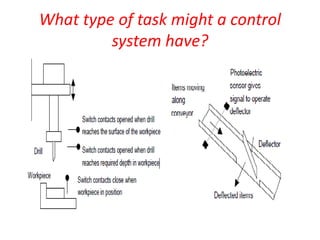
- 1. What type of task might a control system have?
- 2. What form might a controller have?
- 3. Microprocessor controlled system • If switch A closes • Output to motor circuit • If switch B closes • Output to valve circuit By changing the instructions in the program we can use the same microprocessor system to control a wide variety of situations.
- 4. The programmable logic controller A programmable logic controller (PLC) is a special form of microprocessor- based controller that uses a programmable memory to store instructions and to implement functions such as logic, sequencing, timing, counting and arithmetic in order to control machines and processes
- 5. Components of the PLC
- 8. 1 The processor unit or central processing unit (CPU) is the unit containing the microprocessor and this interprets the input signals and carries out the control actions, according to the program stored in its memory, communicating the decisions as action signals to the outputs. 2 The power supply unit is needed to convert the mains a.c. voltage to the low d.c. voltage (5 V) necessary for the processor and the circuits in the input and output interface modules.
- 9. 3 The programming device is used to enter the required program into the memory of the processor. The program is developed in the device and then transferred to the memory unit of the PLC. 4 The memory unit is where the program is stored that is to be used for the control actions to be exercised by the microprocessor and data stored from the input for processing and for the output for outputting. 5 The input and output sections are where the processor receives information from external devices and communicates information to external devices.
- 10. The programmable logic controller
- 11. The programmable logic controller
- 12. INPUT SENSORS
- 13. OUTPUT DEVICES • - DC MOTOR • -AC MOTOR • LIGHTS • ALARMS • HEATING ELEMENTS
- 15. The CPU 1 An arithmetic and logic unit (ALU) which is responsible for data manipulation and carrying out arithmetic operations of addition and subtraction and logic operations of AND, OR, NOT and EXCLUSIVE-OR. 2 Memory, termed registers, located within the microprocessor and used to store information involved in program execution. 3 A control unit which is used to control the timing of operations.
- 16. The buses DATA BUS ADDRESS BUS CONTROL BUS
- 17. Memory 1 System read-only-memory (ROM) to give permanent storage for the operating system and fixed data used by the CPU. 2 Random-access memory (RAM) for the user’s program.
- 18. Input/output unit 1. The input/output unit provides the interface between the system and the outside world, allowing for connections to be made through input/output channels to input devices such as sensors and output devices such as motors and solenoids. 2. The input/output channels provide isolation and signal conditioning functions so that sensors and actuators can often be directly connected to them without the need for other circuitry.
- 24. UNITARY PLC
- 25. MODULAR PLC
- 26. PLC BOTTLE FILLING PLANT
- 27. User program execution • The basic PLC scan cycle consists of three steps – An input scan – A user program scan – An output scan • The total time for one complete program scan is a function of processor speed, I/O modules used, and length of user program
- 28. Input scan • During the input scan, data is taken from all input modules in the system and placed into an area of PLC memory referred to as the input image area
- 29. Input scan
- 30. User program scan • During the program scan, data in the input image area is applied to the user program, the user program is executed and the output image area is updated
- 32. Output scan • During the output scan, data is taken from the output image area and sent to all output modules in the system
- 33. Output scan
- 34. PLC scanning considerations • During the input scan, input terminals are read and the input image area is updated accordingly. • During the program scan – data in the input image area is applied to the user program – the program is executed (instructions carried out in sequence) – the output image area is updated appropriately • During the output scan, data associated with the output image area is transferred to output terminals
- 35. • Any changes in the status of input devices during the program or output scan are not recognized until the next input scan • Furthermore, data changes in the output table are not transferred to the output terminals during the input and program scans • The transfer affecting the output devices takes place only during the output scan
- 36. PLC scanning considerations • Typically, the program scanning takes place left to right across each rung and from the top to bottom rungs, in order • Usually, the complete ladder scan time is a few milliseconds
- 37. Rung scanning
- 38. Two-rung ladder logic program
- 39. Two-rung ladder logic program
- 40. Scan cycle
- 41. I/O DEVICES • Mechanical switches • A mechanical switch generates an on−off signal or signals as a result of some mechanical input causing the switch to open or close.
- 42. LIMIT SWITCHES • The term limit switch is used for a switch which is used to detect the presence or passage of a moving part.
- 43. Proximity switches • Proximity switches are used to detect the presence of an item without making contact with it.
- 44. Photoelectric sensors and switches • Photoelectric switch devices can either operate as transmissive types where the object being detected breaks a beam of light, usually infrared radiation, and stops it reaching the detector or reflective types where the object being detected reflects a beam of light onto the detector.
- 45. Photoelectric sensors and switches
- 46. Encoders • The term encoder is used for a device that provides a digital output as a result of angular or linear displacement. • With 60 slots then, since one revolution is a Rotation of 360, a movement from one slot to the next is a rotation of 6.
- 48. absolute encoder • With 4 tracks there will be 4 bits and so the number of positions that can be detected is 24 = 16, i.e. a resolution of 360/16 = 22.5. • An absolute encoder gives the actual angular or linear position
- 49. absolute encoder
- 50. Temperature sensors • A simple form of temperature sensor which can be used to provide an on–off signal when a particular temperature is reached is the bimetal element. • This consists of two strips of different metals, e.g. brass and iron, bonded together .The two metals have different coefficients of expansion.
- 51. Position/displacement sensors • The term position sensor is used for a sensor that gives a measure of the • distance between a reference point and the current location of the target
- 53. Strain gauges • When a wire or strip of semiconductor is stretched, its resistance changes. • The fractional change in resistance is proportional to the fractional change in length, i.e. strain.
- 54. Strain gauges
- 55. Pressure sensors • When a piezoelectric crystal is squeezed, there is a relative displacement of positive and negative charges within the crystal and the outer surfaces of the crystal become charged. Hence a potential difference appears across it.
- 56. Relay • When a current passes through a solenoid a magnetic field is produced and this can then attract ferrous metal components in its vicinity.
- 57. Motors • A d.c. motor has coils of wire mounted in slots on a cylinder of ferromagnetic material, this being termed the armature. The armature is mounted on bearings and is free to rotate. It is mounted in the magnetic field produced by permanent magnets or current passing through coils of wire, these being termed the field coils. When a current passes through the armature coil, forces act on the coil and result in rotation.
- 58. Motors
- 59. Stepper motors • When one pair of poles is activated, a magnetic field is produced which attracts the nearest pair of rotor teeth so that the teeth and poles line up. This is termed the position of minimum reluctance.
- 60. Stepper motors
- 61. A conveyor belt • When an item is loaded onto the conveyor belt, a contact switch might be used to indicate that the item is on the belt and start the conveyor motor. The motor then has to keep running until the item reaches the far end of the conveyor and falls off into the packaging area.