Scaling API-first – The story of a global engineering organization
Xy rectify tip_sheet
1. XYRectify tip sheet
This tip sheet was prepared for users with a working knowledge of
the iWitnessTM close-range photogrammetry software system
1. Best to calibrate the camera in iWitness, and use the focal length at the
calibration setting for imaging with XYRectify
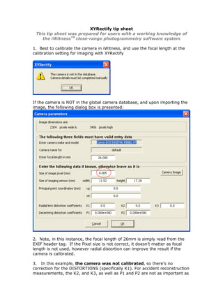
If the camera is NOT in the global camera database, and upon importing the
image, the following dialog box is presented:
2. Note, in this instance, the focal length of 26mm is simply read from the
EXIF header tag. If the Pixel size is not correct, it doesn’t matter as focal
length is not used, however radial distortion can improve the result if the
camera is calibrated.
3. In this example, the camera was not calibrated, so there’s no
correction for the DISTORTIONS (specifically K1). For accident reconstruction
measurements, the K2, and K3, as well as P1 and P2 are not as important as
2. K1. If the camera has been calibrated, then it is best to click the “Apply
corrections” box. The pixel size (mm) should be proper relative to the
c(mm) focal length. NOTE: it is always better to work with a camera that’s
been calibrated with iWitness to optimize accuracy!
4. At this point, the camera parameters are setup and the image will be
imported into XYRectify.
5. Control Points:
XYRectify requires a minimum of 4 control points that are on a fairly planar
surface (in this example a roadway intersection.) The control points are XY
coordinates that should be accurate. In this instance a total station was used
to derive the coordinates, but a total station is not the only way of obtaining
these XY coordinates.
Create a Control Point file using MS Notepad. Type in the name of the
control point, and then its X, and Y coordinates. See the below screen
capture:
3. In our example” Lwr_BE” means
“Lower Bulls-Eye” as defined by
the white X and the white
circle in the image.
Left_CL is the end of the double
centerline on the left side (note:
the image is actually illustrated
upside down, so that is why it
appears “opposite” in the image
marking process noted on the
6. Click on the File + Import Control next page.)
7. The Import Control thumbnail is presented in the thumbnails on the left of
the image. Click it and the control points dialog is presented.
Click in the Label field with the “red plus” and it becomes a “yellow plus”.
4. Mark the corresponding location of the control point in the image and it
becomes a “green plus”.
Do this action for the remaining (minimum) of 4 control points.
Note that the “Rectified Image” in the lower left of the dialog box displays
two options, “Full Image” and “Bounded by control points”. The default is
Full Image. The operator can choose to rectify either the entire original
image (full image), which is the default case or a portion of the original
image (bounded by control points …) equal to the area encompassed by the
control points, plus a border area of approximately 10%.. In this example,
we are going to leave the tick mark on the default “Full Image”.
The below illustrates all 5 Control Points Marked, from the Control Points
Dialog Box:
5. 8. Click the “Create Image”
The Save As dialog will now be presented. Name the resulting Projective
Transformation Image a new name; (we’ll call it “Crash”). Save it to your
working folder.
The new image named “Crash.jpg” is now planar rectified and an image
thumbnail of it is presented above the Control Points dialog box:
9. Output File from XYRectify:
The saved JPEG is accompanied by ‘tfw’ or ‘World files’ which define the XY
reference coordinate system for the rectified image. The TFW (ASCII text
file) is named the same name as your image; (in this example case
“Crash.twf” located in your working directory.
The image can now be imported into your favorite CAD package.