SlideShare uma empresa Scribd logo
1 de 252
Baixar para ler offline
RANGEMASTER 2700-B
ANLEITUNG | INSTRUCTIONS
NOTICE D’UTILISATION | GEBRUIKSAANWIJZING
ISTRUZIONI | INSTRUCCIONES
BRUKSANVISNING | ИНСТРУКЦИЯ
RANGEMASTER 2700-B
ANLEITUNG | INSTRUCTIONS
NOTICE D’UTILISATION | GEBRUIKSAANWIJZING
ISTRUZIONI | INSTRUCCIONES
BRUKSANVISNING | ИНСТРУКЦИЯ
AbC
EHr
HOLd
1(1MOA)
1-4(1MOA)
1-3(1MOA)
10
5
SId
100(yds/m)
200(yds/m)
300(yds)
GEE(m)
bALL
US1/EU1
US12/EU12
Card
OFF
EUUS
US
EU
MENU
RANGEMASTER 2700-B
ANLEITUNG | INSTRUCTIONS
NOTICE D’UTILISATION | GEBRUIKSAANWIJZING
ISTRUZIONI | INSTRUCCIONES
BRUKSANVISNING
DE
2
3
4
5
6
4
7
11
8
9
Dieses Produkt wird hergestellt unter Lizenz von Leupold & Stevens, Inc.
10
1 2 3a
DE
3
BEZEICHNUNG DER TEILE
1 Nebentaste
2 Haupttaste
3 Augenmuschel mit
a. Dioptrienskala
4 Öse für Trageschnur
5 Okular
6 Batteriefachdeckel
7 Batteriefach
8 Objektivlinse
9 Abdeckkappe über Speicherkartenschacht
10 Speicherkartenschacht
(Abdeckkappe geöffnet)
11 Laser-Sendeoptik
DE
4
LASER-SICHERHEITSHINWEISE
Im Leica Rangemaster wird ein unsichtbarer Laser-
strahl eingesetzt. Stellen Sie sicher, das Folgende
zu beachten:
WARNUNG:
Nichtbeachtung folgender Punkte kann zu schweren
Verletzungen oder zum Tod führen.
•	Werden andere als die in dieser Anleitung aufge-
führten Bedienungsvorgänge verwendet, bzw.
Anpassungen am Gerät vorgenommen, kann es
zum Austritt gefährlicher Strahlung kommen.
•	So lange Sie die Anzeige im Okular sehen ist das
Produkt aktiv, sendet einen unsichtbaren Laser-
strahl aus und die Laser-Fokussieroptik darf
nicht auf jemanden gerichtet sein.
•	Demontieren oder verändern Sie den Leica
Rangemaster nicht; wenn die interne Elektronik
freigelegt wird, kann dies zu Schäden oder
Stromschlägen führen.
•	Drücken Sie keine der beiden Tasten, während
Sie auf ein menschliches Auge zielen oder die
Optik von der Objektivseite aus betrachten.
•	Bewahren Sie den Leica Rangemaster nicht in
Reichweite von kleinen Kindern auf.
VORSICHT:
Nichtbeachtung folgender Punkte kann zu Verlet-
zungen oder zur Beschädigung des Geräts führen.
•	Richten Sie den Laser nicht auf ein Auge.
•	Richten Sie den Laser nicht auf Menschen.
•	Betreiben Sie den Leica Rangemaster nicht mit
anderen zusätzlichen optischen Elementen, wie
Objektiven oder Ferngläsern. Eine Verwendung des
Leica Rangemasters zusammen mit einem opti-
schen Gerät erhöht die Gefahr einer Verletzung der
Augen.
•	Wird die Entfernungsmessung gerade nicht
benötigt, sollten Sie es vermeiden, eine der
beiden Tasten zu betätigen, um ein unbeabsich-
tigtes Abgeben des Laserstrahls zu vermeiden.
•	Entfernen Sie die Batterie aus dem Gehäuse,
wenn Sie den Leica Rangemaster für längere Zeit
nicht verwenden.
•	Sie dürfen den Leica Rangemaster nicht zerle-
gen, neu zusammensetzen oder reparieren. Die
ausgehende Laserstrahlung kann Ihre Gesund-
heit gefährden. Ein einmal zerlegtes, neu zusam-
mengesetztes oder repariertes Gerät unterliegt
nicht mehr der Herstellergarantie.
DE
5
•	Ist das Gehäuse des Leica Rangemasters
beschädigt oder gibt das Gerät nach einem Fall
oder aus einem anderen Grund einen fremdarti-
gen Ton ab, so entnehmen Sie bitte sofort die
Batterie und verwenden ihn nicht mehr.
TECHNISCHE DATEN DES LASERS
Laserklasse IEC/EN Class 1
Wellenlänge (nm) 897
Pulsdauer (ns) 64
Ausgangsleistung (mW) 0,965
Strahlendivergenz
(mrad)
Vertikal: 1,28,
Horizontal: 0,85
Das Produktionsdatum finden Sie auf den Aufkle-
bern in der Garantiekarte und/oder auf der Verpa-
ckung. Die Schreibweise des Datums ist:
Jahr/Monat/Tag.
DE
6
VORWORT
Wir wünschen Ihnen viel Freude und Erfolg mit
Ihrem neuen Leica Rangemaster. Dieser Entfer-
nungsmesser sendet unsichtbare und für das Auge
unschädliche Infrarot-Impulse aus und berechnet
über einen eingebauten Mikroprozessor aus dem
reflektierten Signalanteil die Objektentfernung.
Darüber hinaus erfasst er Umgebungs- und Einsatz-
bedingungen. Mit diesen ermittelt er – zusammen
mit den gemessenen Entfernungen - entsprechende
Korrekturen des Haltepunkts für verschiedene,
wählbare Ballistik-Kurven und zeigt diese an. Er ist
mit einer hervorragenden, 7fach vergrößernden
Zieloptik ausgestattet, die auch unter schwierigen
Bedingungen eine sichere Peilung ermöglicht.
Darüber hinaus ist der Leica Rangemaster einfach
und funktional zu bedienen. Damit Sie alle Möglich-
keiten dieses hochwertigen und vielseitigen Laser-
Entfernungsmessgerätes richtig nutzen können,
empfehlen wir Ihnen, zunächst diese Anleitung zu
lesen.
Entsorgung elektrischer und
elektronischer Geräte
(Gilt für die EU sowie andere europäische
Länder mit getrennten Sammelsystemen)
Dieses Gerät enthält elektrische und/oder elektro-
nische Bauteile und darf daher nicht im normalen
Hausmüll entsorgt werden! Stattdessen muss es
zwecks Recycling an entsprechenden, von den
Gemeinden bereitgestellten Sammelstellen abgege-
ben werden. Dies ist für Sie kostenlos. Falls das
Gerät selbst wechselbare Batterien oder Akkus
enthält, müssen diese vorher entnommen werden
und ggf. Ihrerseits vorschriftsmäßig entsorgt wer-
den (siehe dazu die Angaben in der Anleitung des
Geräts). Weitere Informationen zum Thema bekom-
men Sie bei Ihrer Gemeindeverwaltung, Ihrem
Entsorgungsunternehmen, oder dem Geschäft, in
dem Sie dieses Gerät erworben haben.
DE
7
LIEFERUMFANG
–– Entfernungsmesser
–– 1 Lithium Rundzelle 3V Typ CR 2
–– Trageriemen
–– microSD-Speicherkarte 8 GB
–– microSD Karten-Adapter
–– Corduratasche
–– Garantiekarte
–– Prüfzertifikat
Warnhinweis
Vermeiden Sie, wie bei jeder Optik, den
direkten Blick mit Ihrem Leica Rangemaster
in helle Lichtquellen, um Augenverlet-
zungen auszuschließen.
DE
8
INHALTSVERZEICHNIS
Bezeichnung der Teile........................................... 3
Vorwort................................................................. 6
Lieferumfang......................................................... 7
Auswechseln der Batterie.................................... 10
Ladezustand der Batterie.................................... 10
Verwendung mit und ohne Brille.......................... 11
Dioptrien-Ausgleich............................................. 11
Grundsätzliches zur Menüsteuerung.................... 12
Einstellung der gewünschten Maßeinheit............. 12
Entfernungsmessung........................................... 13
Scan-Betrieb....................................................... 15
Messreichweite und Genauigkeit......................... 16
Anzeige der atmosphärischen Bedingungen......... 17
Bestimmen der Ballistik-Kurve............................. 18
Einstellen der Ballistik-Kurve................................ 19
Einstellen der Fleckschuss-Entfernung................. 20
Ballistische Ausgabeformate............................... 20
Einstellungen und Auswahl der
ballistischen Ausgabeformate.............................. 21
Die äquivalente horizontale Entfernung................ 22
Der Haltepunkt................................................... 22
Treffpunktkorrektur mittels Elevationsverstellung......23
Anzeige und Überprüfung der
eingestellten Ballistik-Parameter.......................... 23
Einsetzen beliebiger Ballistik-Kurven.................... 24
Was tun, wenn.................................................... 27
Technische Daten............................................... 28
Pflege/Reinigung................................................ 30
Ersatzteile........................................................... 30
Leica Service-Adressen....................................... 31
Anhang
Ballistik-Tabellen............................................... 244
DE
9
TRAGERIEMEN ANBRINGEN
Bitte die kleine Schlaufe der Trageriemen durch die
Öse 4 am Gehäuse des Leica Rangemaster schie-
ben. Dann das Ende der Trageriemen durch die
kleine Schlaufe fädeln und so festziehen, dass sich
die entstandene Schlinge fest um die Öse am
Gehäuse legt.
DE
10
AUSWECHSELN DER BATTERIE
Der Leica Rangemaster wird zur Energieversorgung
mit einer 3 Volt Lithium-Rundzelle (z. B. Duracell DL
CR2, Ucar CR2, Varta CR2, oder anderen CR2-
Typen) bestückt.
1. Öffnen Sie den Deckel 6 des Batteriefachs 7,
indem Sie ihn gegen den Uhrzeigersinn drehen.
2. Legen Sie die Batterie mit ihrem Pluskontakt
voran (entsprechend der Kennzeichnung im
Batteriefach) ein.
3. Schließen Sie den Deckel wieder durch Drehen
im Uhrzeigersinn.
Hinweise:
• Kälte reduziert die Batterieleistung. Bei niedrigen
Temperaturen sollte der Leica Rangemaster
deshalb möglichst in Körpernähe getragen und
mit einer frischen Batterie betrieben werden.
• Wenn der Leica Rangemaster längere Zeit nicht
benutzt wird, sollte die Batterie herausgenom-
men werden.
• Batterien sollten kühl und trocken gelagert
werden.
Achtung:
• Batterien dürfen keinesfalls ins Feuer geworfen,
erhitzt, wieder aufgeladen, zerlegt oder aufgebro-
chen werden.
• Verbrauchte Batterien dürfen nicht in den norma-
len Hausmüll geworfen werden, denn sie enthal-
ten giftige, die Umwelt belastende Substanzen.
Um sie einem geregelten Recycling zuzuführen,
sollten sie beim Handel abgegeben oder zum
Sondermüll (Sammelstelle) gegeben werden.
LADEZUSTAND DER BATTERIE
Eine verbrauchte Batterie wird durch eine blinkende
Messwert- und Zielmarkenanzeige signalisiert. Nach
dem erstmaligen Blinken der Anzeige sind noch
mehr als 100 Messungen mit fortschreitend verrin-
gerter Reichweite möglich.
DE
11
VERWENDUNG MIT UND OHNE BRILLE
A B
Beobachter, die keine Brille tragen, lassen die
Gummi-Augenmuschel 3 hochgeklappt (Bild A,
Lieferzustand). In dieser Position ist der richtige
Abstand des Leica Rangemaster zum Auge gege-
ben. Beim Beobachten mit Brille wird die Gummi-
Augenmuschel umgestülpt (Bild B).
DIOPTRIEN-AUSGLEICH
Mit dem Dioptrien-Ausgleich können Sie die
Schärfe der Zielmarke und der Anzeigen auf den für
Sie optimalen Wert einstellen. Einfach durch den
Leica Rangemaster ein weit entferntes Objekt
anpeilen und durch Drehen an der Augenmuschel 3
die Zielmarke auf optimale Schärfe einstellen. Sie
erscheint bei Druck auf die Haupttaste 2. Den
eingestellten Wert können Sie an der Skala 3a auf
der Augenmuschel ablesen. Ein Dioptrien-Ausgleich
ist für Fehlsichtigkeiten bis ± 3,5 Dioptrien möglich.
DE
12
GRUNDSÄTZLICHES ZUR MENÜSTEUERUNG
Das Hauptmenü besteht aus den vier Menüpunk-
ten:
–– 	Meter-/Yard-Anzeige (EU.US)
–– 	Ballistik-Kurve (bALL)
–– 	Fleckschussentfernung (SId)
–– 	ballistische Ausgabeformate (AbC)
Einzelheiten zu den Funktionen finden sie in den
jeweiligen Abschnitten.
Grundsätzlich gilt:
Sowohl das Hauptmenü als auch die jeweiligen
Einstellungsoptionen der einzelnen Menüpunkte
sind als Endlos-Schleifen geschaltet, d. h. alle
Punkte/Einstellungen sind durch mehrfachen
Tastendruck immer wieder zu erreichen.
EINSTELLUNG DER GEWÜNSCHTEN
MAßEINHEIT
Der Leica Rangemaster kann auf das metrische
oder imperiale Maßeinheitensystem eingestellt
werden, d. h. für Entfernung/Temperatur/Luftdruck
entweder Meter/Celsius/Millibar oder entspre-
chend Yards/Fahrenheit/InHg (Inches of Mercury).
Diese Einstellung bestimmt auch die Einheiten des
Haltepunktes, der Ballistik-Kurven und der
Fleckschuss-­Entfernungen.
1.	 	Drücken Sie die Nebentaste 1 lang (≥ 3 s).
•	Es erscheint EU.US (blinkend).
2.	 	Drücken Sie die Haupttaste 2, um die
gewünschte Maßeinheit auszuwählen.
US = für Anzeige in Yards
EU = für Anzeige in Meter
DE
13
Hinweis:
Die jeweilige Einstellung ist stets an der Anzeige zu
erkennen: Zusätzlich zu den Ziffern erscheint M (für
Meter) oder Y (für Yards).
3.	 	Speichern Sie Ihre Einstellung durch kurzes
Drücken ( 2 s) der Nebentaste.
•	Die gespeicherte Einstellung leuchtet zur
Bestätigung zunächst dauerhaft, anschlie-
ßend wechselt die Anzeige zunächst zum
nächsten Menüpunkt (Ballistik-Kurve bALL)
und erlischt danach, sofern keine weiteren
Einstellungen vorgenommen wurden.
DE
14
ENTFERNUNGSMESSUNG
9 8
Um die Entfernung zu einem Objekt zu messen,
muss es genau angepeilt werden. Gehen Sie dazu
wie folgt vor:
1. Drücken Sie die Haupttaste 2.
Das Gerät schaltet sich ein.
• Die Zielmarke erscheint.
Nach dem Loslassen der Haupttaste leuchtet die
Zielmarke noch für ca. 6 Sekunden weiter. Wird sie
gedrückt gehalten, leuchtet die Zielmarke perma-
nent.
2. Peilen Sie das Objekt an, während die Ziel-
marke leuchtet.
3. Drücken Sie erneut die Haupttaste.
a. Die Zielmarke erlischt während der Messung
kurzzeitig.
b. Der Messwert wird angezeigt.
Solange die Zielmarke noch leuchtet, kann jederzeit
eine neue Messung durch erneuten Druck auf die
Haupttaste gestartet werden.
Es erscheint: - - -, wenn
– die Objektentfernung weniger als 10 Meter
beträgt, oder
– die Reichweite überschritten wird, oder
– das Objekt ungenügend reflektiert.
Mit dem Erlöschen der Anzeige schaltet sich der
Leica Rangemaster automatisch ab.
DE
15
SCAN-BETRIEB
6 1 6 3
7 2
Mit dem Leica Rangemaster kann auch im Dauerbe-
trieb (Scan-Betrieb) gemessen werden:
Halten Sie die Haupttaste 2 bei der zweiten Betäti-
gung gedrückt. Nach ca. 2,5 Sekunden schaltet
sich das Gerät in den Scan-Betrieb und führt dann
permanent Messungen durch. Zu erkennen ist dies
an der wechselnden Anzeige. Nach jeweils
ca. 0,5 Sekunden wird ein neuer Messwert ausge-
geben.
Der Scan-Betrieb ist besonders praktisch bei der
Messung auf kleine und sich bewegende Ziele.
Hinweise:
• Im Scan-Betrieb wird der AbC-Korrekturwert (s.
S. 15) erst nach der letzten Messung ange-
zeigt.
• Im Scan-Betrieb ist der Stromverbrauch aufgrund
der permanenten Messungen höher als bei
Einzelmessungen.
DE
16
MESSREICHWEITE UND GENAUIGKEIT
Die maximale Reichweite des Leica Rangemaster
wird erreicht bei gut reflektierenden Zielobjekten
und einer visuellen Sichtweite von etwa10 km. Hohe
Reichweiten können sicherer gemessen bzw.
erreicht werden, wenn der Leica Rangemaster
entweder sehr ruhig gehalten und/oder aufgelegt
wird. Die Messreichweite wird von folgenden
Faktoren beeinflusst:
Reichweite höher geringer
Farbe weiß schwarz
Winkel zum
Objektiv
senkrecht spitz
Objektgröße groß klein
Sonnenlicht wenig
(bewölkt)
viel
(Mittagssonne)
Atmosphärische
Bedingungen
klar dunstig
Bei Sonnenschein und guter Sicht gelten folgende
Reichweiten bzw. Genauigkeiten:
Reichweite ca. 10 - 2500 m
Genauigkeit –– 800 - 2500 m: ca. ± 0,5 %
–– 400 - 800 m: ca. ± 2 m
–– 200 – 400 m: ca. ± 1 m
–– 10 – 200 m: ca. ± 0,5 m
Hinweis:
Entfernungen unterhalb von 200 m werden ein-
schließlich einer Dezimalstelle angezeigt, z. B. 164.5.
DE
17
ANZEIGE DER ATMOSPHÄRISCHEN
BEDINGUNGEN
1 5 6 3 C
1 0 3 0
Für die genaue Berechnung der Treffpunktlage
(siehe dazu den folgenden Abschnitt) ermittelt der
Leica Rangemaster während der Entfernungsmes-
sung zusätzlich drei wichtige Zusatzinformationen:
– die Neigung des Geräts
– die Temperatur
– den Luftdruck.
Die jeweiligen Werte können Sie sich jederzeit
anzeigen lassen.
Drücken Sie die Nebentaste 1 1x kurz.
• Die Zielmarke erscheint kurzzeitig (falls nicht
vorher bereits die Entfernungsmessung einge-
schaltet war). Anschließend erscheinen statt der
Entfernung für jeweils ca. 2 s nacheinander
– der Neigungswinkel (durch zusätzliches
Winkel-Symbol gekennzeichnet)
– die Temperatur
– der Luftdruck
Hinweis:
Wenn das Gehäuse des Leica Rangemaster, bei-
spielsweise beim Übergang von Innenräumen nach
draußen, eine deutlich von der Umgebung abwei-
chende Temperatur aufweist, kann es bis zu 30 min
dauern, bis der innen liegende Messfühler wieder
die korrekte Umgebungstemperatur anzeigt.
DE
18
BESTIMMEN DER BALLISTIK-KURVE
Zur präzisen Bestimmung der Treffpunktkorrektur
bezieht der Leica Rangemaster die Geschossflug-
bahn auf Grundlage des verwendeten Kalibers
sowie Geschossart und -gewicht in die Berechnung
mit ein. Dies beinhaltet auf Wunsch die Anpassung
der Berechnung der äquivalenten horizontalen
Entfernung (EHr, s. S. 21), des Haltepunkts (HOLd,
s. S. 22) oder der Absehen-Verstellung (1/1-4/1-
3/10/5, s. S. 22). Zu dem Zweck stehen Ihnen 12
unterschiedliche, fest programmierte Ballistik-Kur-
ven zur Auswahl. Suchen Sie in der Tabelle im
Anhang, die der eingestellten Fleckschuss-Entfer-
nung entspricht, die Ballistik-Kurve, die den Anga-
ben des Munitionsherstellers zur Treffpunktlage am
nächsten kommt.
Beispiel:
Das Zielfernrohr ist auf 100 m eingeschossen, es
gilt also Tabelle 1. Als Treffpunktlage für die verwen-
dete Munition wird -15,0 cm auf 200 m angegeben.
In der entsprechenden Spalte entspricht das am
ehesten dem Wert 14,5 cm in der Zeile EU7 – dies
ist also die passende Ballistik-Kurve.
Hinweis:
Bei der Verwendung der Ballistik-Funktion des Leica
Rangemaster auf größere Entfernungen als 300 m,
und/oder beim Einsatz anderer, nicht durch die
Geräteinternen Einstellungen abgedeckten Muniti-
onsarten empfehlen wir Ihnen, entweder die ballisti-
schen Daten Ihrer Munition durch praktische
Versuche zu ermitteln, um die entsprechend pas-
sende Kurve auswählen zu können, oder sie mit
Hilfe des Leica Ballistik-Rechners zu ermitteln und
per Speicherkarte auf das Gerät zu übertragen.
DE
19
Einstellen der Ballistik-Kurve
Beginnen Sie mit Schritt 1., wenn Sie die Menü-
steuerung vorher noch nicht aufgerufen hatten,
oder mit Schritt 3., wenn Sie vorher gerade die
Maßeinheit eingestellt hatten und die Anzeige bAll
noch blinkt.
1.	 Drücken Sie die Nebentaste 1 lang (≥ 3 s).
•	Es erscheint EU.US.
2.	 Drücken Sie die Nebentaste 1x kurz ( 2 s).
•	Die Anzeige wechselt zu den Ballistik-Kurven
bALL.
3.	 Drücken Sie die Haupttaste 2.
•	Die Anzeige wechselt zu
–– EU1 oder
–– US1
Hinweis:
Ist eine Speicherkarte eingesetzt (s. S. 25),
erscheint CArd vor EU1 / US1.
4.	 Durch mehrfaches kurzes Drücken der Haupt-
taste wählen Sie die gewünschte Ballistik-
Kurve, d. h.
–– EU1 bis EU12 oder US1 bis US12, bzw.
–– OFF, wenn Sie die Entfernungsanzeige ohne
Treffpunkt-Korrekturanzeige (AbC, s. S. 21
ff) wünschen.
5.	 Speichern Sie Ihre Einstellung durch kurzes
Drücken der Nebentaste.
•	Die gespeicherte Einstellung leuchtet zur
Bestätigung 4 s dauerhaft, anschließend
wechselt die Anzeige zunächst zur Einstel-
lung der Fleckschussentfernung (SId) und
erlischt danach.
Ist eine Ballistik-Kurve eingestellt, wird nach jeder
Entfernungsmessung zunächst für 2 s der Entfer-
nungswert angezeigt, danach für 6 s die errechne-
ten Korrekturwerte.
DE
20
EINSTELLEN DER FLECKSCHUSS-
ENTFERNUNG (SId)
Beginnen Sie mit Schritt 1., wenn Sie die Menü-
steuerung vorher noch nicht aufgerufen hatten, mit
Schritt 3., wenn Sie vorher gerade die Ballistik-
Kurve festgelegt hatten und die Anzeige SId noch
blinkt.
1.	 	Drücken Sie die Nebentaste 1 lang (≥ 3 s).
Es erscheint EU.US.
2.	 Drücken Sie die Nebentaste 2x kurz ( 2 s)
Die Anzeige wechselt über bALL zu SId.
3.	 	Durch mehrfaches Drücken der Haupttaste 2
wählen Sie die gewünschte Fleckschuss-Entfer-
nung.
–– 100 [m],
–– 200 [m], oder
–– GEE [m], bzw.
–– 100 [y], oder
–– 200 [y], oder
–– 300 [y].
4.	 Speichern Sie Ihre Einstellung durch kurzes
Drücken der Nebentaste.
•	Die gespeicherte Einstellung leuchtet zur
Bestätigung 4 s dauerhaft, anschließend
wechselt die Anzeige zunächst zu AbC und
erlischt danach.
BALLISTISCHE AUSGABEFORMATE (AbCTM
)
Die Advanced Ballistic Compensation (AbC) des
Leica Rangemaster ermöglicht es Ihnen, sich im
Anschluss an die gemessene Entfernung auf
Wunsch einen der folgenden drei ballistischen
Werte anzeigen zu lassen:
–– die äquivalente horizontale Entfernung (EHr)
–– den entsprechenden Haltepunkt (HOLd)
–– die Anzahl der erforderlichen Klicks an der
Absehen-Schnellverstellung (MOA/Klicks)
Sowohl der angezeigte Haltepunkt als auch der
angezeigte EHr-Wert berücksichtigen:
a.	die gemessene Entfernung zum Ziel,
b.	den Neigungswinkel,
c.	die eingestellte Ballistik-Kurve,
d.	die gemessenen Temperatur- und Luftdruck-
Werte
e.	die eingestellte Fleckschuss-Entfernung
Hinweise:
•	Die Berechnung der genannten Werte beruht auf
der jeweils eingestellten Ballistik-Kurve, d. h.
diese muss vorher ausgewählt werden (s.
S. 18).
DE
21
•	Ballistische Ausgabewerte werden aus Sicher-
heitsgründen nur bis zu einer Entfernung von
800 m angegeben. Darüber hinaus wird nur die
tatsächlich gemessene Entfernung angegeben.
Wichtig:
•	Bitte beachten Sie, dass gerade bei großen
Entfernungen der Einfluss aller ballistisch rele-
vanten Einflussfaktoren deutlich zunimmt und es
zu erheblichen Abweichungen kommen kann. Die
angezeigten ballistischen Werte sind deshalb
ausdrücklich als Hilfsmittel zu verstehen!
•	Unabhängig von der Nutzung dieser Information
unterliegt die Einschätzung der jeweiligen jagdli-
chen Situation Ihrer Verantwortung!
EINSTELLUNGEN UND AUSWAHL DER
BALLISTISCHEN AUSGABEFORMATE
Beginnen Sie mit Schritt 1, wenn Sie die Menüsteu-
erung vorher noch nicht aufgerufen hatten, mit
Schritt 3., wenn Sie vorher gerade die Fleckschuss-
Entfernung eingestellt hatten und die Anzeige ABC
noch blinkt.
1.	 Drücken Sie die Nebentaste 1 lang (≥ 3 s).
•	Es erscheint EUUS.
2.	 	Drücken Sie die Nebentaste 3x kurz ( 2 s)
•	Die Anzeige wechselt über bALL und SId zu
AbC.
•	
3.	 Durch mehrfaches Drücken der Haupttaste 2
wählen Sie die gewünschte ballistische Einstel-
lung.
–– EHr, oder
–– HOLd, oder
–– 1 (1 MOA), (Anzeige in Dezimal)
–– 1-4 (1⁄4 MOA), bzw.
–– 1-3 (1⁄3 MOA), bzw.
–– 10 mm, bzw.
–– 5 mm.
4.	 Speichern Sie Ihre Einstellung durch kurzes
Drücken der Nebentaste.
•	Die gespeicherte Einstellung leuchtet zur
Bestätigung 4 s dauerhaft, anschließend
erlischt die Anzeige.
DE
22
DIE ÄQUIVALENTE HORIZONTALE
ENTFERNUNG (EHr)
Schüsse auf höher oder tiefer gelegene Ziele
unterliegen veränderten ballistischen Bedingungen.
Sie erfordern daher die Kenntnis der - jagdlich
relevanten - äquivalenten horizontalen Entfernung
(Equivalent Horizontal Range). Die Kenntnis der EHr
ist z. B. beim Einsatz von ballistischen Absehen
wichtig. EHr-Werte werden durch die zusätzliche
Anzeige gekennzeichnet.
Hinweis:
Auch horizontale EHr-Messungen können Werte
ergeben, die von der „geradlinig“ gemessenen
Entfernung abweichen, wenn beispielsweise die
Temperatur und/oder der Luftdruck von den
Normalwerten abweichen.
DER HALTEPUNKT (HOLd)
Als Haltepunkt wird derjenige Punkt bezeichnet, der
anstatt des eigentlichen Zielpunkts mit der Waffe
anvisiert wird, um die durch die Flugbahn des
Geschosses verursachte Abweichung auszugleichen
(z. B. bei der Verwendung klassischer jagdlicher
Absehen). Durch die Anzeige des Haltepunkts kann
der Leica Rangemaster im jagdlichen Einsatz
wertvolle Unterstützung für das Anbringen mög-
lichst präziser Schüsse leisten. Grundlage der
Berechnung sind neben der Entfernung die im
vorigen Abschnitt erwähnten Rahmenbedingungen
und die von Ihnen gewählte Ballistik-Kurve.
Hinweis:
Jede angezeigte Schusskorrektur bezieht sich
immer auf die Distanz zwischen dem Anwender und
dem Ziel.
Beispiel: Wird 300m und anschließend 30 angezeigt,
müssten Sie auf dem Objekt 30 cm höher anhalten,
als es ohne Korrektur der Fall wäre.
DE
23
TREFFPUNKTKORREKTUR MITTELS
ELEVATIONSVERSTELLUNG (Klick-/MoA-
Verstellung)
Abweichungen der Treffpunktlage können durch
entsprechende Verstellung des Absehens an Ihrem
Zielfernrohr ausgeglichen werden. Der Leica Range-
master kann Ihnen – unter Berücksichtigung der
Geschossflugbahn und der Fleckschuss-Entfernung
(s. S. 20) - die dazu erforderliche Verstellung,
d. h. die jeweilige Anzahl der Klicks anzeigen. Für
verschiedene Elevationen können Sie dabei vorge-
ben, ob die Klick-Stufen
–– auf der Grundlage der international üblichen
MOA-Einteilung (Minutes Of Angle), oder
–– in 5- bzw. 10-Millimeter-Abstufungen ausgege-
ben werden sollen.
Anzeige und Überprüfung der eingestell-
ten Ballistik-Parameter
Wenn Sie Ihre Einstellungen überprüfen möchten,
können Sie sich die Werte jederzeit anzeigen
lassen:
Drücken Sie die Nebentaste 1 2x kurz.
•	Unterhalb der Zielmarke erscheinen (ggf. statt
der Entfernung) für jeweils ca. 2 s nacheinander
–– die eingestellte Ballistik-Kurve (s. S. 18)
–– die eingestellte Fleckschuss-Entfernung (s.
S. 20)
–– der eingestellte ballistische Ausgabewert (s.
S. 21)
Hinweis:
Bei Abschaltung aller ballistischen Funktionen
(bALL = OFF) wird dagegen EU oder US angezeigt.
DE
24
EINSETZEN BELIEBIGER
BALLISTIK-KURVEN
Wenn die vorgesehene Waffen-/Geschoss-Kombi-
nation nicht bereits durch eine der einprogrammier-
ten Ballistik-Kurven EU1/US1- EU12/US12 abge-
deckt ist, können Sie mit diesem Leica
Rangemaster auch eigene, individuelle Ballistik-Kur-
ven einsetzen.
Dies erfolgt in vier Schritten:
A. Einsetzen der Micro-SD-Speicherkarte
in ein (mit dem Rechner verbundenes)
Karten-Lesegerät mit Hilfe des mitge-
lieferten SD-Kartenadapters
microSD-
Kartenadapter
microSD-
Speicherkarte
B. Berechnung der gewünschten Ballistik-
Kurve und Übertragen auf eine micro-
SD-Speicherkarte
Den Zugang zum Leica Ballistik-Rechner wie
auch zur dazugehörigen Eingabemaske finden
Sie auf der Seite des Leica Ballistikprogramms
unter
https://de.leica-camera.com/Sportoptik/
Leica-Jagdoptik/Leica-Ballistikprogramm.
DE
25
C. Einsetzen/Herausnehmen der
Speicherkarte in den/aus dem Leica
Rangemaster
D. Aufrufen der Ballistik-Kurve von der
Speicherkarte
Ist eine Speicherkarte in den Leica Rangemaster
eingesetzt, auf der sich eine Ballistik-Kurve
befindet, kann diese aufgerufen werden wie
unter „Einstellen der Ballistik-Kurve“ auf S. 19
beschrieben.
• Nach Drücken der Haupttaste 2 erscheint in
dem Fall als erstes CArd. Wenn anschließend
eine Entfernungsmessung vorgenommen wird
können folgende Warnhinweise erscheinen:
– Err1, wenn das bALL-Menü aufgerufen
wurde, anschließend aber die Speicher-
karte entnommen wird bzw. bei defekten
oder nicht lesbaren Karten. In dem Fall
erlischt auch CArd.
– Err2, wenn sich keine Ballistik-Kurve auf
der Speicherkarte befindet
– Err3, wenn die Ballistik-Kurve auf der
Speicherkarte unkorrekte Daten enthält.
Die weitere Vorgehensweise entspricht
genau der für die fest einprogrammierten
Ballistik-Kurven.
Fortsetzung nächste Seite.
DE
26
Hinweise:
•	Berühren Sie die Kontakte der Speicherkarte
nicht.
•	Falls sich die Speicherkarte nicht einsetzen lässt,
überprüfen Sie ihre korrekte Ausrichtung.
•	Das Angebot an Micro-SD-Karten ist zu groß, als
dass die Leica Camera AG sämtliche erhältlichen
Typen vollständig auf Kompatibilität und Qualität
prüfen könnte. Eine Beschädigung von Entfer-
nungsmesser oder Karte ist zwar in aller Regel
nicht zu erwarten, da jedoch insbesondere
sogenannte no-name-Karten teilweise nicht die
Micro-SD-Standards einhalten, kann die Leica
Camera AG keine Funktionsgarantie überneh-
men.
•		Aus Sicherheitsgründen, d. h. um Verwechslun-
gen auszuschließen, kann immer nur eine ballisti-
sche Kurve auf einer Karte gespeichert werden.
Aus dem gleichen Grund wird eine Datei nicht
erkannt, deren Name Sie verändert haben.
•	Bei der Verwendung von Ballistik-Kurven von der
Speicherkarte werden Entfernungen bis 925 m
angezeigt.
•	Auch wenn eine Speicherkarte eingesetzt ist,
kann jederzeit eine der fest einprogrammierten
Ballistik-Kurven eingestellt werden. Bitte überprü-
fen Sie also immer Ihre Einstellungen
DE
27
WAS TUN, WENN ...
Fehler Ursache	 Abhilfe
Bei der Beobachtung wird kein
kreisrundes Bild erreicht.
a) Pupille des Beobachters liegt nicht in der
Austrittspupille des Okulars.
b) Stellung der Augenmuschel entspricht nicht
der richtigen Benutzung mit und ohne Brille.
a) Augenposition korrigieren.
b) Anpassung korrigieren: Brillenträger kni-
cken die Augenmuschel um; bei Beobach-
tung ohne Brille bleibt sie hochgeklappt
(s. S. 11).
Anzeige unscharf Dioptrienausgleich nicht exakt Dioptrienausgleich erneut durchführen (s.
S. 11)
Bei der Entfernungsmessung
erscheint die Anzeige „- - -“
a) Messbereich über- oder unterschritten
b) Reflexionsgrad des Objekts unzureichend
Angaben zum Messbereich
berücksichtigen (s. S. 13)
Anzeige blinkt oder keine
Messung möglich
Batterie verbraucht Batterie auswechseln (s. S. 10)
DE
28
TECHNISCHE DATEN
Gerätebezeichnung LEICA RANGEMASTER CRF 2700 - B
Typ-Nr. 5630
Vergrößerung 7x
Objektivdurchmesser 24 mm
Austrittspupille 3,4 mm
Dämmerungszahl 13
Geometrische Lichtstärke 11,8
Sehfeld (auf 1.000 m) 115,6 m
Objektiver Sehwinkel 6,6°
Austrittspupillen-Längsabstand 15 mm
Prismenart Dachkant
Vergütung
auf Linsen
auf Prismen
High Durable Coating (HDC™) und Aqua-Dura Vergütung auf Außenlinsen
Phasenkorrekturbelag P 40
Dioptrienausgleich ± 3,5 dpt.
Brillenträgertauglich Ja, durch umstülpbare Gummi-Augenmuschel
Entfernungsmessung
Maximale Reichweite
Äquivalente horizontale Entfernung
Ballistische Ausgabewerte
Mindestentfernung
Messgenauigkeit
Anzeige/Maßeinheit
Maximale Messdauer
Messmethoden
ca. 2500 m
ca. bis 1100 m
ca. bis 800 m
ca. 10 m
800 - 2500 m: ca. ± 0,5 %:/400 - 800 m: ca. ± 2 m/200 – 400 m: ca. ± 1 m/ 10 –
200 m: ca. ± 0,5 m
LED mit 4 Ziffern plus Zusatzzeichen, wahlweise in Meter/Zentimeter, bzw. yards/inches
ca. 0,3 s
Einzelmessung, Scanbetrieb
DE
29
Laser
Laserstrahl-Divergenz
Unsichtbar, augensicher nach EN und FDA Klasse 1
ca. 0,5 x 1,2 mrad
Gehäuse-/Chassismaterial Kohlefaser-verstärkter Kunststoff, softlackiert / Magnesium-Druckguss
Schnittstellen
Speicherkarte Schlitz mit Abdeckkappe für micro-SD-Speicherkarte, mitgelieferter SD-Kartenadapter
erlaubt die Verwendung in SD-Kartenlesegeräten
Wasserdichtigkeit
Gehäuse
Speicherkartenschacht
Für 30 min: druckwasserdicht bis 1 m Wassertiefe
Spritzwasser-geschützt
Funktionstemperatur -20 bis 55 °C
Lagertemperatur -40 bis 85 °C
Batterie Lithium-Rundzelle 3V Typ CR2
Batterielebensdauer ca. 2.000 Messungen bei 20 °C
Abmessungen (B x H x T) ca. 75 x 34 x 113 mm
Gewicht (mit Batterie) ca. 185 g
Änderungen in Konstruktion, Ausführung und Angebot vorbehalten.
DE
30
PFLEGE/REINIGUNG
Eine besondere Pflege Ihres Leica Rangemaster ist
nicht notwendig. Grobe Schmutzteilchen, wie z. B.
Sand sollten mit einem Haarpinsel entfernt oder
weggeblasen werden. Fingerabdrücke u. Ä. auf
Objektiv- und Okularlinsen können mit einem
feuchten Tuch vorgereinigt und mit einem weichen,
sauberen Leder oder staubfreien Tuch abgewischt
werden.
Wichtig:
Üben Sie auch beim Abwischen stark verschmutzter
Linsenoberflächen keinen großen Druck aus. Die
Vergütung ist zwar sehr abriebfest; durch Sand oder
Salzkristalle kann sie dennoch beschädigt werden.
Das Gehäuse sollte nur mit einem feuchten Tuch ge-
reinigt werden. Bei Verwendung von trockenen Tü-
chern besteht die Gefahr der statischen Aufladung.
Alkohol und andere chemische Lösungen dürfen
nicht zur Reinigung der Linsen oder des Gehäuses
verwendet werden. Jeder Leica Rangemaster trägt
außer der Typbezeichnung seine „persönliche“ Fab-
rikationsnummer. Notieren Sie sich diese Nummer
zur Sicherheit in Ihren Unterlagen.
Achtung:
Das Gerät darf auf keinen Fall geöffnet werden!
ERSATZTEILE
Falls sie einmal Ersatzteile für Ihren Leica Range-
master benötigen sollten, wie z. B. Augenmuschel
oder Trageriemen, wenden Sie sich bitte an unseren
Product Support-Abteilung (Adresse s. S. 31) oder
Ihre Leica Landesvertretung (Adressen siehe Leica
Camera AG Homepage).
Anmerkungen zum Anhang:
•	In den Tabellen 1, 2 und 3 sind die Entfernungen
in Metern, die Geschossabfall-Werte in Zentime-
tern angegeben, in den Tabellen 4, 5 und 6 in
Yards bzw. Inches.
•	Alle Werte gelten für:
–– einen Luftdruck von 1013 mbar
–– eine Temperatur von 20 °C
–– horizontale Schüsse
DE
31
LEICA PRODUCT SUPPORT
Anwendungstechnische Fragen zu den Leica Pro-
dukten beantwortet Ihnen schriftlich, telefonisch
oder per E-Mail die Product Support-Abteilung der
Leica Camera AG.
Leica Camera AG
Product Support / Software Support
Am Leitz-Park 5
D-35578 Wetzlar
Tel.: +49(0)6441-2080-111 /-108
Fax: +49(0)6441-2080-490
info@leica-camera.com /
software-support@leica-camera.com
LEICA CUSTOMER CARE
Für die Wartung Ihrer Leica-Ausrüstung sowie in
Schadensfällen stehen Ihnen die Customer Care-
Abteilung der Leica Camera AG oder der Reparatur-
dienst einer Leica-Landesvertretung zur Verfügung
(Adressenliste siehe Leica Camera AG Homepage).
Leica Camera AG
Customer Care
Am Leitz-Park 5
D-35578 Wetzlar
Tel.: +49(0)6441-2080-189
Fax: +49(0)6441-2080-339
customer.care@leica-camera
EN
32
3
4
5
6
4
7
11
8
9
This product is manufactured under license from Leupold  Stevens, Inc.
10
1 2 3a
EN
33
DESIGNATION OF PARTS
1 Secondary button
2 Main button
3 Eyecup with
a. Diopter scale
4 Eyelet for carrying strap
5 Eyepiece
6 Battery compartment cover
7 Battery compartment
8 Lens
9 Protection flap over memory card slot
10 Memory card slot
(protection flap open)
11 Laser transmission lens
EN
34
WARNING
This indication alerts you to the fact that any improper
use ignoring the contents described herein can result
in potential death or serious injury.
CAUTION
This indication alerts you to the fact that any improper
use ignoring the contents described herein can result
in potential injury or material loss.
SAFETY PRECAUTIONS (Laser)
The Leica Rangemaster uses an invisible laser beam.
Be sure to observe the following:
WARNING
•	 Use of controls or adjustments or performance of
procedures other than those specified herein may
result in hazardous radiation exposure
•	 When you see the display through the eyepiece,
please be aware that the product is active and
emitting an invisible laser and the laser aperture
should not be pointed toward anyone
•	 Do not take the product apart or modify the product
in any way to expose internal electronics that might
cause damage or electric shock
•	 Do not depress any button while aiming at a human
eye or while looking into the optics from the objec-
tive side
•	 Do not leave the Leica Rangemaster within the
reach of small children
CAUTION
•	 Do not aim at the eye.
•	 Do not point the laser at people.
•	 Do not operate the unit with other additional optical
elements, such as lenses or binoculars. Using an
optical instrument together with the Leica Range-
master increases the danger of damaging the eyes.
•	 When not measuring, please keep your fingers away
from any button to avoid accidentally emitting the
laser beam.
•	 When not in use for an extended period, please
remove the battery from the body.
EN
35
•	 Do not disassemble/remodel/repair the Leica
Rangemaster. The emitting laser may be harmful to
your health. A product that has been disassembled/
remodeled/repaired is not guaranteed by the
manufacturer.
•	 If the Leica Rangemaster’s body cover is damaged,
or if it emits a strange sound due to dropping or
some other cause, remove the battery immediately
and stop using.
Technical Data (Laser)
Class IEC/EN Class 1
Wavelength (nm) 897
Pulse duration (ns) 64
Output (mW) 0,965
Beam divergence (mrad) Vertical: 1,28,
Horizontal: 0,85
This product is in conformity with performance stan-
dards for laser products under 21 CFR 1040, except
with respect to those characteristics authorized by
Variance Number FDA-2016-V-3483 effective Novem-
ber 4, 2016
The production date can be found on the stickers in the
Guarantee Card and/or on the packaging.
The date is written as follows: Year/Month/Day
EN
36
FOREWORD
We wish you a great deal of enjoyment and every
success with your new Leica Rangemaster. This
rangefinder emits invisible infrared impulses that are
not harmful to the viewer’s eyes and uses an integrated
microprocessor to calculate the distance to an object
from the reflected signal component. In addition, it
registers ambient and situational parameters. With
these - and the measured distance - it calculates the
respective holdover values for different, selectable
ballistic curves and displays them. It features an
outstanding scope with 7x magnification, ensuring a
reliable bearing even under difficult conditions. Plus,
the Leica Rangemaster is easy to handle and operate.
To ensure that you get the best out of this high-quality
and versatile laser rangefinder, we recommend reading
these instructions first.
Disposal of electrical and electronic
equipment
(Applies within the EU, and for other Euro-
pean countries with segregated waste
collection systems)
This device contains electrical and/or electronic
components and must therefore not be disposed
of in general household waste! Instead, it should be
disposed of at a recycling collection point provided
by the local authority. This costs you nothing. If the
device contains standard or rechargeable batteries,
these must be removed first and also be disposed of
in line with relevant regulations (for details, refer to the
instructions of your device) Further information on this
issue is available from your local administration, your
local waste collection company, or in the store where
you purchased this device.
EN
37
SCOPE OF DELIVERY
–– Rangefinder
–– 1 lithium battery 3V, type CR 2
–– Carrying strap
–– microSD memory card 8 GB
–– microSD card adapter
–– Cordura case
–– Guarantee Card
–– Test certificate
Warning note
As with all binoculars, avoid looking directly at
bright light sources with your Leica Range-
master in order to avoid eye damage.
EN
38
TABLE OF CONTENTS
Designation of Parts..................................................33
Foreword..................................................................36
Scope of delivery......................................................37
Changing the battery.................................................40
Battery charge level..................................................40
Use with and without glasses....................................41
Diopter compensation...............................................41
Basic information on menu control............................42
Setting the unit of measure.......................................42
Distance measurement.............................................43
Scan mode...............................................................45
Measuring range and accuracy..................................46
Indication of atmospheric conditions.........................47
Determining the ballistic curve..................................48
Setting the ballistic curve..........................................49
Setting of zero-range distance...................................50
Ballistic output formats.............................................50
Settings and selection of ballistic output formats.......51
Equivalent horizontal distance...................................52
Holdover...................................................................52
Impact point correction
using elevation adjustment........................................53
Displaying and checking the set
ballistic parameters...................................................53
Use of any ballistic curves.........................................54
Troubleshooting........................................................56
Technical data..........................................................58
Care/cleaning..........................................................60
Spare parts...............................................................60
Appendix
Ballistic Tables........................................................244
EN
39
ATTACHING THE CARRYING STRAP
Feed the small loop on the carrying strap through the
eyelet 4 on the housing of the Leica Rangemaster.
Then thread the end of the strap through the small loop
and pull tight, so that the resulting loop is securely
around the eyelet on the housing.
EN
40
CHANGING THE BATTERY
The Leica Rangemaster is powered by a cylindrical
3 Volt lithium cell (e.g. Duracell DL CR2, Ucar CR2,
Varta CR2, or other CR2 types).
1. Open the cover 6 on the battery compartment 7
by turning it counter-clockwise.
2. Insert the battery so that the positive contact goes
in first (as shown by the markings in the battery
compartment).
3. Close the cover again by turning it clockwise.
Notes:
• Cold conditions impair the battery performance. At
low temperatures the Leica Rangemaster should be
kept as close to the body as possible and a new
battery should be fitted.
• If the Leica Rangemaster will not be used for a long
period, the battery should be removed.
• Batteries should be stored in a cool dry place.
Attention:
• Batteries should never be put in a fire, heated,
recharged, taken to pieces or broken apart.
• Used batteries may not be disposed of as normal,
household waste as they contain toxic materials that
are harmful to the environment. To ensure that they
are properly recycled, they should be returned to
the dealer or disposed of as special waste (at a
collection point).
BATTERY CHARGE LEVEL
A used battery is indicated by a flashing measured
value and reticule display. Once the display starts
flashing, at least another 100 measurements are
possible, with a gradually reducing range.
EN
41
USE WITH AND WITHOUT GLASSES
A B
Users who do not wear glasses can leave the rubber
eyecup 3 folded up (Figure A, as supplied). This
position gives the correct distance between the Leica
Rangemaster and the eye. When using the Leica
Rangemaster with glasses, the rubber eyecup should
be folded down (Figure B).
DIOPTER COMPENSATION
Diopter compensation enables you to adjust the
sharpness of the reticule to the optimum value for you.
Simply aim the Leica Rangemaster at a distant object
and adjust the reticule until it has optimum sharpness
by turning the eyecup 3. The reticule appears when
you press the main button 2. You can read the set
value on the “+” or “-” scale 3a on the eyecup. Diopter
compensation is available for vision defects of up to ±
3.5 diopters.
EN
42
BASIC INFORMATION ON MENU CONTROL
The main menu is made up of four menu items:
–– 	Meter/Yard Display (EU.US)
–– 	Ballistic curve (bALL)
–– 	Zeroing distance (SId)
–– 	ballistic output formats (AbC)
Details of the individual functions can be found in the
relevant sections.
Generally:
Both the main menu and the setting options are set up
as a continuous loop - i.e. all items/settings are
accessible by continually pressing the button.
SETTING THE UNIT OF MEASURE
The Leica Rangemaster can be set to metric or imperial
units of measure, i.e. for distance/temperature/
atmospheric pressure either meters/Celsius/millibar
or yards/Fahrenheit/InHg (Inches of Mercury). This
setting also determines the details of the holdover, the
ballistic curves and the zeroing distance.
1.	 	Press and hold the secondary button 1 (≥ 3 s).
•	 EU.US appears (flashing).
2.	 	Press the main button 2 to select the desired unit
of measure.
US = for display in yards
EU = for display in meters
EN
43
Note:
The current setting can always be seen in the display:
M (for meters) or Y (for yards) appears in addition to
the digits display.
3.	 	Save your setting by briefly pressing the second-
ary button ( 2 s).
•	 The saved setting is initially lit continuously as
confirmation, then the display switches to the
next item in the menu (ballistics curve „bALL“)
and then disappears if no further settings have
been made.
EN
44
DISTANCE MEASUREMENT
9 8
To measure the distance to an object, you must aim
directly at it. To do this, proceed as follows:
1. Press the main button 2.
This switches on the device.
• The reticule appears.
When you release the main button, the reticule remains
lit for around another 6 seconds. If you hold it down,
the reticule remains lit continuously.
2. Aim at the object while the reticule is lit.
3. Press the main button again.
a. The reticule disappears briefly during the mea-
surement.
b. The measured value is displayed.
As long as the reticule remains lit, you can carry out
another measurement at any time by pressing the main
button again.
- - - appears, if
– the distance to the object is less than 10 yards,
or
– the range is exceeded, or
– the object is not sufficiently reflective.
When the display disappears, the Leica Rangemaster
shuts down automatically.
EN
45
SCAN MODE
6 1 6 3
7 2
The Leica Rangemaster can also be used for continu-
ous measurements (scan mode):
Press and hold the main button 2 at the 2nd press.
After around 2.5 seconds, the device switches to scan
mode and then carries out continuous measurements.
This can be seen by a change in the display. Around
every 0.5 seconds, a new measured value is shown.
Scan mode is particularly useful for measuring the
range to small or moving targets.
Notes:
• In scan mode, the AbC compensation value (see
p. 45) is displayed after the last measurement.
• Because of the continuous measurements, power
consumption is greater in scan mode than for single
measurements.
EN
46
MEASURING RANGE AND ACCURACY
The maximum range is achieved with highly reflective
target objects and a visual range of sight of around
11000 yards. Long ranges can be reliably measured /
achieved by holding the Leica Rangemaster very
steadily and/or placing it on a solid surface. The
measuring range is influenced by the following factors:
Range longer shorter
Color white black
Angle to lens perpendicular acute
Object size large small
Sunlight low
(cloudy)
high
(midday sun)
Atmospheric
conditions
clear hazy
In sunlight and with good vision, the following ranges
and accuracies can be achieved:
Range approx. 10-2500 m/ 11-2700 yds
Accuracy –– 800 - 2500 m / 875 - 2700 yds:
approx. ± 0.5%
–– 400-800 m / 437-875 yds:
approx. ± 2 yds
–– 200-400 m / 219-437 yds:
approx. ± 1 yd
–– 10-200 m / 11-219 yds:
approx. ± 0.5 m/yds
Note:
Distances below 200 m/219 yds are shown with an
accuracy of one decimal place, e. g. 164.5
EN
47
INDICATION OF ATMOSPHERIC CONDITIONS
1 5 6 3 C
1 0 3 0
To accurately calculate the impact point (see following
section), the Leica Rangemaster also determines three
crucial pieces of additional information when measur-
ing the range:
– the inclination of the unit
– temperature
– atmospheric pressure
You can display the relevant values at any time.
Press the secondary button 1 briefly 1x.
• The reticule appears briefly (if distance measure-
ment was not previously activated) and then the
following items appear in succession for around 2 s
each instead of the range:
– inclination (indicated by an additional angle
symbol)
– temperature
– atmospheric pressure
Note:
If the housing of the Leica Rangemaster initially has a
significantly different temperature than the surround-
ings, for example when moving from inside to outside,
it can take up to 30 minutes before the internal sensor
can display the correct ambient temperature again.
EN
48
DETERMINING THE BALLISTIC CURVE
For the precise determination of the impact point
correction, the Leica Rangemaster includes the bullet
trajectory on the basis of the used caliber, as well as
the bullet type and weight in the calculation. This
includes the adjustment of the calculation of the
equivalent horizontal distance (EHr, see p. 51) of the
holdover (HOLd, see p. 22 ) or the sight adjustment
(1/1-4/1-3/10/5, see p. 52) on request. Twelve
different ballistic curves are available for adaptation to
the equipment you are using. From the appropriate
table in the appendix, find the ballistic curve that is
closest to the bullet drop specified by the ammunition
manufacturer. Make sure you choose the appropriate
down range distance.
Example:
The rifle scope is zeroed to 100 meters, which means
that Table 1 is applicable. The specified impact point
for the ammunition used is -15.0 cm at 200 m. In the
corresponding column, this is closest to the value 14.5
cm in row EU7 - this is therefore the appropriate
ballistic curve.
Note:
When using the Leica Rangemaster’s ballistic function
at distances longer than 330 m/yds and/or other
ammunition types that are not covered by the internal
settings of the device, we recommend to either deter-
mine the ballistic data of your ammunition through
practical testing to choose the appropriate curve, or to
determine it with the Leica ballistics calculator and to
transfer it by memory card to the device.
EN
49
Setting the ballistic curve
Start with step 1 if you have not previously opened the
menu control, or with step 3 if you have just set the
unit of measure and bAll is still flashing in the display.
1.	 Press and hold the secondary button 1 (≥ 3 s).
•	 EU.US appears.
2.	 Press the secondary button briefly ( 2 s) once.
•	 The display switches to the ballistic curves
bALL.
3.	 Press the main button 2.
•	 The display switches to
–– EU1 or
–– US1
Note:
When a memory card is inserted (see p. ??),
CArd appears before EU1 / US1.
4.	 By pressing the main button repeatedly, select the
desired ballistic curve, i.e.
–– EU1 to EU12 or US1 to US12, or
–– OFF, if you want to have a distance display
without point of impact settings display (AbC,
see p. 51 ff).
5.	 Save your setting by briefly pressing the second-
ary button.
•	 The saved setting is initially lit continuously for
4 s as confirmation, then the display changes
first to the zeroing distance setting (SId) and
then disappears.
If a ballistic curve is set, after each distance measure-
ment the range value is first displayed for 2 s, then the
calculated correction value for 6 s.
EN
50
SETTING OF ZEROING DISTANCE (SId)
Start with step 1 if you have not previously opened the
menu control, or with step 3 if you have just set the
unit of measure and SId is still flashing in the display.
1.	 	Press and hold the secondary button 1 (≥ 3 s).
EU.US appears.
2.	 Press the secondary button briefly ( 2 s) once.
The display switches from bALL to SId.
3.	 	By pressing the main button 2 repeatedly, select
the desired down range distance.
–– 100 [m],
–– 200 [m] or
–– GEE [m] or
–– 100 [y] or
–– 200 [y] or
–– 300 [y].
4.	 Save your setting by briefly pressing the second-
ary button.
•	 The saved setting is initially lit continuously for
4 s as confirmation, then the display switches
to AbC and then disappears.
BALLISTIC OUTPUT FORMATS (AbCTM
)
The advanced ballistic compensation (AbC) on the Leica
Rangemaster allows you to display one of the following
three ballistic values after the measured range if
required:
–– the equivalent horizontal range (EHr)
–– the corresponding holdover (HOLd)
–– the number of clicks required on the rapid reticle
adjustment (MOA/clicks)
Both the displayed holdover and EHr values factor in:
a.	the measured range to the target
b.	the angle of inclination of the weapon
c.	the set ballistic curve
d.	the measured temperature and atmospheric
pressure values
e.	the set zeroing distance
Notes:
•	 Calculation of the specified values is based on the
currently set ballistic curve, i.e. the curve must be
selected first (see p. 48).
•	 For safety reasons, ballistic output values are only
specified up to a range of 800 m/yds. The actual
measured range is also specified.
EN
51
Important:
•	 Please note that particularly at long ranges, the
influence of all relevant ballistic influencing factors
is greatly increased and considerable variations can
occur. The ballistic values displayed should there-
fore only be viewed as a guideline.
•	 Regardless of whether this information is used, you
are responsible for assessing the relevant hunting
situation.
SETTINGS AND SELECTION OF BALLISTIC
OUTPUT FORMATS
Start with step 1 if you have not previously opened the
menu control, or with step 3 if you have just set the
down range distance and ABC is still flashing in the
display.
1.	 Press and hold the secondary button 1 (≥ 3 s).
•	 EUUS appears.
2.	 	Press the secondary button briefly ( 2 s) once.
•	 The display switches from bALL and SId to AbC.
•	
3.	 By pressing the main button 2 repeatedly, the
desired ballistic setting is selected.
–– EHr or
–– HOLd or
–– 1 (1 MOA), (display in decimal)
–– 1-4 (1⁄4 MOA) or
–– 1-3 (1⁄3 MOA) or
–– 10 mm or
–– 5 mm.
4.	 Save your setting by briefly pressing the second-
ary button.
•	 The saved setting is initially lit continuously for
4 s as confirmation, then the display disap-
pears.
EN
52
EQUIVALENT HORIZONTAL RANGE (EHr)
Shots at targets at a higher or lower elevation are
subject changed ballistic conditions. Therefore, they
require knowledge of the equivalent horizontal range,
which is relevant for hunting. Knowledge of the EHr is
important when using ballistic reticles, for example. EHr
values are indicated by the additional display .
Note:
Horizontal EHr measurements can also result in values
that differ from the „straight line“ measured range, for
example if the temperature and/or the atmospheric
pressure vary from the normal values.
HOLDOVER (HOLd)
Holdover is defined as the point that you aim at with
the weapon instead of the actual target point to
compensate for the variation caused by the trajectory
of the bullet (e.g. when using classic hunting reticles).
By displaying the holdover, the Leica Rangemaster can
provide valuable support in achieving the most accu-
rate shots possible when hunting. In addition to the
range, the calculation is based on the general condi-
tions discussed in the previous section and the ballistic
curve you have selected.
Note:
The holdover/elevation is always shown with reference
to the range to the target.
Example: If 300m 30 is displayed, you would have to aim
30 cm higher on the object than without correction.
EN
53
IMPACT POINT CORRECTION USING ELE-
VATION ADJUSTMENT (Click/MoA adjustment)
Variations in the point of impact can be compensated
by adjusting the reticle on your riflescope accordingly.
Based on the bullet trajectory and the zeroin distance,
the Leica Rangemaster can show you the required
adjustment, i.e. the relevant number of clicks. For
different elevations, you can specify whether the click
levels will be
–– based on the international standard MOA (min-
utes of angle) graduation, or
–– displayed in 5 or 10 millimeter increments.
Displaying and checking the set ballistic
parameters
If you want to check your settings, you can display the
values at any time.
Press the secondary button 1 briefly 2x.
•	 Below the reticule (instead of the range, if this was
previously displayed), the following will appear in
turn for around 2 s each:
–– the set ballistic curve
–– the set zeroing distance
–– the set ballistic output value
Note:
When all ballistic functions are deactivated (bALL =
OFF), only the OFF setting is displayed.
EN
54
USE OF ANY BALLISTIC CURVES
If the intended combination of weapon and ammunition
is not already covered by one of the programmed
ballistic curves EU1 / US1-EU12 / US12, you can also use
your own, individual ballistic curves with the Leica
Rangemaster.
This is done in four steps:
A. Insertion of the Micro-SD memory card
in a card reader via the supplied SD
card adapter
(connected to a computer)
microSD
memory card adapter
microSD
memory card
B. Calculation of the desired ballistic
curve and transfer to the Micro-SD
memory card
Access to the Leica Ballistic Calculator as well as
the respective entry mask can be found on the
Leica Ballistic Program page under
https://de.leica-camera.com/Sportoptik/Lei-
ca-Jagdoptik/Leica-Ballistikprogramm
EN
55
C. Inserting / Removing the memory card
into / from the Leica Rangemaster
D. Opening the ballistic curve from the
memory card
If a memory card with a ballistic curve is inserted
into the Leica Rangemaster, it can be selected just
as described under “Setting the ballistic curve” on
p. 49.
• After pressing the main button 2 CArd appears
first in this case. If a distance measurement is
subsequently performed, the following warning
messages may appear:
– Err1 if the bALL menu was selected, but the
memory card is removed, defect or nonread-
able. In this case, CArd also disappears.
– Err2 if there is no ballistic curve on the
memory card.
– Err3 if the ballistic curve on the memory card
does not contain correct data. The following
procedure corresponds to the one for the
programmed ballistic curves.
Continued on next page.
EN
56
Notes:
•	 Do not touch the memory card contacts.
•	 If the memory card cannot be inserted, check that it
is aligned correctly.
•	 The range of available microSD memory cards is too
large for Leica Camera AG to be able to completely
test all available types for compatibility and quality.
Although no damage to the rangefinder or the card
is generally expected, because some so-called no
name cards may not fully comply with the microSD
standards Leica Camera AG cannot provide any
guarantee of function.
•	 	For safety reasons, that is to avoid confusion, only
one ballistic curve can be saved on a card. For the
same reason, a file will not be recognized if you
change its name.
•	 When using ballistic curves from the memory card,
distances of up to 925 m/1000 y will be displayed.
•	 Even though a memory card is inserted, one of the
programmed ballistic curves can be selected at any
time. Hence, please always check your settings.
EN
57
TROUBLESHOOTING
Problem Cause	 Remedy
The image seen viewing through the
binoculars is not perfectly circular.
a) Your pupil is not in line with the exit pupil of
the eyepiece.
b) Eyecup setting not correct for use with/
without glasses.
a) Adjust eye-to-eyepiece alignment
c) Adjust the settngs: Wearer of glasses fold
the eyecup back; in case of use without
glasses, the eyecup remains folded out (s.
p. 41).
Diplay blurred Diopter setting incorrect Repeat diopter adjustment (see p. 41)
When attempting a measurement, the
display„- - -“ appears
a) Minimum/maximum measuring range
exceeded
b) Target object’s reflectivity is insufficient
Take the specified ranges into account (see
p. 43)
Display flashes or no measurement
possible
Battery exhausted Replace battery (see p. 40)
EN
58
TECHNICAL DATA
Designation LEICA RANGEMASTER CRF 2700 - B
Type No. 5630
Magnification 7x
Lens diameter 24 mm/15/16 in
Exit pupil diameter 3.4 mm/9/64 in
Twilight factor 13
Relative brightness 11.8
Field of view (at 1,000 m/yds) 115.6 m/yds
Subjective viewing angle 6.6 °
Eye relief 15 mm/19/32 in
Prism system Roof
Coating
on lenses
on prisms
High Durable Coating (HDC™) and Aqua-Dura coating on external lenses
Phase correction coating P40
Diopter compensation ± 3.5 dpt.
Suitable for use when wearing
glasses
Yes, with the help of the rubber eyecup which can be folded down
Distance measurement
Maximum range
Equivalent horizontal distance
Ballistic output values
Minimum range
Measuring accuracy
Display/Unit of measure
Maximum measurement duration
Metering methods
approx. 2500 m/2734 yds
approx. to 1100 m/1203 yds
approx. to 800 m/875 yds
approx. 10 m/11 yds
800-2500 m / 875-2734 yds: approx. ± 0.5% / 400-800 m/ 437-875 yds: approx.
± 2 m/6ft 6 in / 200–400 m/219-437 yds: approx. ± 1 m/3ft 3 in / 10–200 m/11-
219 yd: ca. ± 0.5 m/ 1ft 7 in
4-digit LED with additional characters, choice of meters/centimeters or yards/inches
approx. 0.3 s
Single measurement, scan mode
EN
59
Laser
Laser beam divergence
Invisible, safe for eyes in compliance with EN and FDA Class 1
approx. 0.5 x 1.2 mrad
Body/chassis material Carbon fiber reinforced plastic, soft lacquered / cast magnesium
Interfaces
Memory cards Slot with cover for Micro-SD cards, supplied SD card adapter allows the use with SD
card readers
Waterproofing
Body
Memory card slot
For 30 min: waterproof to 1 m/3 ft depth
Splash water protected
Operating temperature range -20 to 55°C / -4 to 130°F
Storage temperature -40 to 85°C / -40 to 185°F
Battery Cylindrical 3 V lithium cell, type CR2
Battery life approx. 2,000 measurements at 20°C/68°F
Dimensions (W x H x D) approx. 75 x 34 x 113 mm / 2 61/64 x 1 11/32 x 4 29/64 inch
Weight (with battery) approx. 185 g / 6.5 oz
Subject to changes in design, production, and scope of delivery.
EN
60
CARE/CLEANING
Your Leica Rangemaster requires no special care.
Coarse particles of dirt such as sand should be
removed with a hair brush or blown away. Fingerprints
or similar on objective and eyepiece lenses can be
pre-cleaned with a damp cloth and then wiped off with
a soft, clean chamois or dust-free cloth.
Important:
Do not exert excessive pressure, even when wiping
very dirty lens surfaces. Although the coating is highly
abrasion-resistant, it can nevertheless be damaged by
sand or salt crystals.
The housing should be cleaned only using a damp
cloth. There is a risk of static charges if dry cloths are
used. Alcohol and other chemical solutions must not
be used to clean the lens surfaces or the housing. In
addition to the designation by type, each Leica Range-
master has an individual serial number. Please note this
number in your documents as a safety measure.
Attention:
Never open the unit.
SPARE PARTS
Please contact the Leica Camera AG Product Support
department (address see p. 31) or your national Leica
representative (for address, see Leica Camera AG
homepage) if you ever need spare parts for your Leica
Rangemaster like an eyecup or a carrying strap.
Comments:
•	 Tables 1, 2 and 3 show the ranges in meters and the
holdover corrections in centimeters, while tables 4
and 5 use yards and inches.
•	 All values are applicable for:
–– a barometric pressure of 1013 mbar
–– a temperature of 20°C/68°F
–– horizontal shots
EN
61
LEICA PRODUCT SUPPORT
The Leica Camera AG Product Support department can
provide you with an answer to any technical application
questions relating to the Leica products either in
writing, on the telephone or by e-mail.
Leica Camera AG
Product Support / Software Support
Am Leitz-Park 5
35578 Wetzlar, Germany
Tel.: +49(0)6441-2080-111 /-108
Fax: +49(0)6441-2080-490
info@leica-camera.com /
software-support@leica-camera.com
LEICA CUSTOMER CARE
The Leica Camera AG Customer Care department or
the repair service provided by authorized Leica agents
in your country are available for service, maintenance
and repairs of your Leica equipment (see the Leica
Camera AG homepage for a list of addresses).
Leica Camera AG
Customer Care
Am Leitz-Park 5
35578 Wetzlar, Germany
Tel.: +49(0)6441-2080-189
Fax: +49(0)6441-2080-339
customer.care@leica-camera
EN
62
FOR US ONLY
FCC Note:
This equipment has been tested and found to comply
with the limits for a Class B digital device, pursuant to
Part 15 of the FCC Rules. These limits are designed to
provide reasonable protection against harmful interfer­
ence in a residential installation. This equipment
generates, uses, and can radiate radio frequency
energy and, if not installed and used in accordance
with the instructions, may cause harmful interference
to radio communications. However, there is no guar­
antee that interference will not occur in a particular
installation. If this equipment does cause harmful
interference to radio or television reception, which can
be determined by turning the equipment off and on,
the user is encouraged to try to correct the interfer-
ence by one or more of the following measures:
• Reorient or relocate the receiving antenna.
• Increase the separation between the equipment and
receiver.
• Connect the equipment into an outlet on a circuit
different from that to which the receiver is con-
nected.
• Consult the dealer or an experienced radio/TV
technician for help.
FCC Caution:
To assure continued compliance, follow the attached
installation instructions and use only shielded inter­face
cables with ferrite core when connecting to com­put­er
or peripheral devices. Any changes or modifications
not expressly approved by the party responsible for
compliance could void the user’s authority to operate
this equipment.
Trade Name: LEICA
Type No. 5630
Responsible party/
Support contact:
Leica Camera Inc.
1 Pearl Count, Unit A,
Allendale, New Jersey 07401
Tel.: +1 201 995 0051/
Fax: +1 201 995 1684
technicalinfo@leicacamerausa.com
EN
63
This device complies with Part 15 of the FCC Rules.
Operation is subject to the following two conditions:
(1) This device may not cause harmful interference,
and (2) this device must accept any interference
received, including interference that may cause
undesired operation.
Type No.: 5630
	Tested To Comply
	 With FCC Standards
FOR HOME OR OFFICE USE
For Canada only:
CAN ICES-3 (B)/NMB-3(B)
FR
64
3
4
5
6
4
7
11
8
9
Ce produit est fabriqué sous licence Leupold  Stevens, Inc.
10
1 2 3a
FR
65
DÉSIGNATION DES PIÈCES
1 Bouton auxiliaire
2 Bouton principal
3 Bonnette avec
a. Graduation dioptrique
4 Œillet pour le cordon de port
5 Oculaire
6 Couvercle du compartiment à piles
7 Compartiment à piles
8 Lentille de l'objectif
9 Capuchon du compartiment de carte mémoire
10 Compartiment de carte mémoire
(capuchon ouvert)
11 Optique d'émission laser
FR
66
MISE EN GARDE
Cette remarque prévient que le non-respect des points
concernés peut provoquer des blessures graves voire
entraîner la mort.
PRUDENCE
Ce symbole indique que le non-respect du contenu
ci-dessous peut entraîner des blessures ou des dégâts
matériels.
CONSIGNES DE SÉCURITÉ (laser)
Le télémètre laser Rangemaster utilise un rayon laser
invisible. Assurez-vous de respecter ce qui suit :
MISE EN GARDE
•	 L’utilisation de commandes, d’ajustements ou de
procédés autres que ceux spécifiés ici peut entraî-
ner l’émission d’un rayonnement dangereux.
•	 Quand vous voyez cet affichage dans l’oculaire, le
produit est activé, il émet un rayonnement laser
invisible et l’orifice de sortie du laser ne doit pas
être dirigé vers une personne
•	 Ne démontez pas ce produit et ne le modifiez pas
pour dégager le système électronique interne ; cela
pourrait provoquer des dégâts ou des décharges
électriques
•	 N’appuyez pas sur la touche Rangemaster alors que
vous pointez l’œil d’une personne ou que vous
regardez le système optique côté objectif
•	 Ne rangez pas le produit Rangemaster à portée de
main des enfants
FR
67
PRUDENCE
•	 Ne pointez pas le laser en direction d’un œil.
•	 Ne pointez pas le laser en direction d’une ou plusieurs
personnes.
•	 N’utilisez pas l’appareil avec d’autres éléments
optiques complémentaires tels que des objectifs ou
des jumelles. L’utilisation du télémètre laser Range-
master en même temps qu’un appareil optique
augmente les risques de blessures aux yeux.
•	 Si une mesure de distance n’est pas spécialement
nécessaire, ne vous approchez pas de la touche
Rangemaster pour éviter l’émission involontaire du
rayonnement laser.
•	 Retirez les batteries du boîtier si vous n’utilisez pas
l’appareil photo pendant une période prolongée.
•	 N’essayez pas de démonter, de remonter ou de réparer
le télémètre laser Rangemaster. Le rayonnement laser
émis peut avoir des conséquences sur votre intégrité
physique. Un produit ayant été démonté, remonté ou
réparé ne bénéficie plus de la garantie du fabricant.
•	 Si le cache du boîtier du télémètre est endommagé ou
encore si l’appareil émet un son à la suite d’une chute
ou pour toute autre raison, retirez immédiatement la
batterie et n’utilisez plus le télémètre.
Caractéristiques techniques (laser)
Classe laser Class 1 IEC/EN
Longueur d'ondes (nm) 897
Durée de pulsation (ns) 64
Puissance de sortie (W) 0,965
Divergence du
rayonnement (mrad)
Verticalement : 1,28
Horizontalement : 0,85
La date de fabrication de votre appareil photo figure sur un
autocollant sur la carte de garantie ou sur l’emballage.
Cette date est indiquée ainsi : année/mois/jour.
FR
68
AVANT-PROPOS
Nous espérons que vous prendrez grand plaisir à
utiliser votre nouveau Leica Rangemaster. Ce télé-
mètre envoie des impulsions infrarouge invisibles et
inoffensives pour les yeux et calcule la distance par
rapport à l'objet par l'intermédiaire d'un microproces-
seur intégré utilisant la partie du signal réfléchie. Par
ailleurs il enregistre les conditions ambiantes et les
conditions d'utilisation. À l'aide de celles-ci, il déter-
mine, grâce aux distances mesurées, les corrections
nécessaires du point de mire pour différentes courbes
balistiques disponibles et les affiche. Il est équipé
d'une optique de visée remarquable d'un grossisse-
ment x7 permettant un relèvement fiable même en
conditions difficiles. Par ailleurs le Leica Rangemaster
est d'une utilisation simple et fonctionnelle. Afin de
pouvoir utiliser correctement toutes les possibilités de
ce télémètre laser haut de gamme polyvalent, nous
vous recommandons de commencer par lire la pré-
sente notice.
Élimination des appareils électriques
ou électroniques
(applicable dans l'UE ainsi que dans les
autres pays européens possédant des
systèmes de tri sélectif)
Cet appareil contient des composants électriques et/
ou électroniques et ne doit donc pas être jeté dans les
ordures ménagères ordinaires. Il doit au contraire être
rapporté à un point de collecte adapté mis à disposi-
tion par les communes pour y être recyclé. C'est
gratuit pour vous. Si l'appareil contient des piles ou
des batteries remplaçables, celles-ci doivent être
préalablement retirées et, le cas échéant, éliminées
séparément par vos soins conformément à la régle-
mentation en vigueur (voir pour cela les indications du
mode d’emploi de l’appareil). D'autres informations à
ce sujet sont disponibles auprès de l'administration
municipale, de la société de traitement des déchets ou
du magasin dans lequel vous avez acheté le présent
appareil.
FR
69
LIVRAISON
–– Télémètre
–– 1 pile cylindrique au lithium 3V type CR2
–– Courroie de port
–– Carte mémoire microSD 8 Go
–– Adaptateur pour carte microSD
–– Sac Cordura
–– Carte de garantie
–– Certificat de contrôle
Avertissement
Comme pour toutes les jumelles, évitez de
regarder directement des sources de lumière
intenses avec votre Leica Rangemaster pour
éviter des lésions oculaires.
FR
70
TABLE DES MATIÈRES
Désignation des pièces.............................................65
Avant-propos............................................................68
Contenu livré............................................................69
Remplacement de la pile...........................................72
État de charge de la pile............................................72
Utilisation avec ou sans port de lunettes...................73
Compensation dioptrique..........................................73
Ce qu'il faut savoir sur la commande du menu...........74
Paramétrage de l'unité de mesure désirée.................74
Mesure de la distance...............................................75
Mode Scan...............................................................77
Portée de mesure et précision...................................78
Affichage des conditions atmosphériques..................79
Détermination de la courbe balistique.......................80
Réglage de la courbe balistique.................................81
Réglage de la distance du point de chute..................82
Formats d'affichage balistiques.................................82
Réglages et sélection des
formats d'affichage balistiques..................................83
La distance horizontale équivalente...........................84
Le point de mire........................................................84
Correction du point d'impact par réglage de l'angle de
hausse......................................................................85
Affichage et vérification des
paramètres balistiques établis...................................85
Insertion d'une sélection
de courbes balistiques..............................................86
Que faire si...............................................................89
Caractéristiques techniques......................................90
Entretien/Nettoyage.................................................92
Pièces de rechange...................................................92
Annexe
Tableaux balistiques................................................244
FR
71
MISE EN PLACE DE LA COURROIE DE
PORT
Introduire la petite boucle de la courroie de port dans
l'œillet 4 du Leica Rangemaster. Faire passer ensuite
l'extrémité du cordon de port dans la petite boucle,
puis serrer de manière que le nœud coulant ainsi formé
soit bien serré autour de l'œillet du boîtier.
FR
72
REMPLACEMENT DE LA PILE
Le Leica Rangemaster est équipé d'une pile cylindrique
au lithium 3 volts (par ex. Duracell DL CR2, Ucar CR2,
Varta CR2 ou d'un autre type CR2).
1. Ouvrez le couvercle 6 du compartiment de la pile
7 en le faisant tourner dans le sens inverse des
aiguilles d'une montre.
2. Insérez la pile avec la borne « plus » vers l'avant
(conformément au schéma figurant dans le
compartiment de la pile).
3. Refermez le couvercle en le faisant tourner dans
le sens des aiguilles d'une montre.
Remarques :
• Le froid réduit les performances de la pile. À basse
température, il convient par conséquent d'utiliser le
Leica Rangemaster le plus près possible du corps et
de le faire fonctionner avec une pile récente.
• Si le Leica Rangemaster reste inutilisé pendant une
assez longue durée, il faut retirer la pile.
• Les piles doivent être stockées dans un endroit frais
et sec.
Attention :
• Ne jetez jamais les piles au feu, ne les chauffez pas,
ne les rechargez pas, ne les ouvrez pas et ne les
cassez pas.
• Les piles usagées ne doivent pas être jetées avec
les déchets domestiques, car elles contiennent des
substances toxiques nocives pour l'environnement.
Afin de les intégrer à un circuit de recyclage, il
convient de les rapporter au magasin ou de les
mettre dans les déchets spéciaux (point de col-
lecte).
ÉTAT DE CHARGE DE LA PILE
Quand la pile est usagée, un clignotement de la cible et
de la valeur mesurée le signale. Après le clignotement
initial de l'affichage, il est encore possible d'effectuer
plus de 100 mesures dont la portée se réduit progres-
sivement.
FR
73
UTILISATION AVEC OU SANS PORT DE
LUNETTES
A B
Un observateur qui ne porte pas de lunettes laissera
les bonnettes en caoutchouc 3 relevées (Ill. A, état à la
livraison). Dans cette position, la distance entre le
Leica Rangemaster et l'œil est idéale. Pour l'observa-
tion avec des lunettes, rabattre les bonnettes en
caoutchouc (Ill. B).
COMPENSATION DIOPTRIQUE
Grâce à la compensation dioptrique, vous pouvez
régler la netteté du repère de visée et les affichages à
la valeur optimale pour vous. Viser simplement un
objet lointain avec le Leica Rangemaster, puis régler la
netteté optimale pour le repère de visée en tournant la
bonnette 3. Le repère de visée apparaît quand vous
appuyez sur le bouton principal 2. Vous pouvez savoir
la valeur de réglage sur l'échelle 3a de la bonnette.
Une compensation dioptrique est possible jusqu'à
± 3,5 dioptries pour prendre en compte les troubles de
la vue.
FR
74
CE QU'IL FAUT SAVOIR SUR LA COMMANDE À
PARTIR DU MENU
Le menu principal comprend les quatre options sui-
vantes :
–– 	affichage mètres/yards (EU.US)
–– 	courbe balistique (bALL)
–– 	distance du point de chute (SId)
–– 	formats d'affichage balistiques (AbC)
Pour plus de détails, voir les paragraphes concernés.
Principe de base :
Le menu principal ainsi que les options de réglage
concernées des différentes options du menu sont
conçus comme des boucles sans fin, c'est-à-dire qu'il
est possible de revenir à chaque point ou réglage en
appuyant plusieurs fois sur les touches.
PARAMÉTRAGE DE
L'UNITÉ DE MESURE DÉSIRÉE
Le Leica Rangemaster peut être paramétré avec le
système d'unités de mesures métrique ou anglo-saxon,
c'est-à-dire pour la distance, la température et la
pression atmosphérique soit mètres / ° Celsius /
millibars soit yards / ° Fahrenheit / InHg (pouces de
mercure). Ce paramétrage détermine également les
unités du point de mire, des courbes balistiques et de
la distance du point de chute.
1.	 	Appuyez sur le bouton auxiliaire 1 pendant un
certain temps (≥ 3 s).
•	 EU.US apparaît (clignotant).
2.	 	Appuyez sur le bouton principal 2 pour sélection-
ner l'unité de mesure désirée.
US = pour l'affichage en yards
EU = pour l'affichage en mètres
FR
75
Remarque :
Le paramètre choisi est toujours identifiable sur
l'affichage : En plus des chiffres apparaît M (mètres)
ou Y (yards).
3.	 	Enregistrez votre paramétrage en appuyant
brièvement ( 2 s) sur le bouton auxiliaire.
•	 Le paramétrage enregistré reste d'abord allumé
en permanence en guise de confirmation, puis
l'option de menu suivante (courbe balistique
bALL) s'affiche et s'éteint ensuite si aucun
autre paramétrage n'est effectué.
FR
76
MESURE DES DISTANCES
9 8
Pour mesurer la distance par rapport à un objet, vous
devez le viser précisément. Pour cela, procédez
comme suit :
1. Appuyez sur le bouton principal 2.
L'appareil s'allume.
• Le repère de visée apparaît.
Lorsque vous relâchez le bouton principal, le repère de
visée reste encore allumé pendant environ 6 secondes.
Tant que vous appuyez sur le bouton principal, le
repère de visée reste allumé.
2. Visez l'objet pendant que le repère de visée est
allumé.
3. Appuyez une nouvelle fois sur le bouton principal.
a. Le repère de visée s'éteint brièvement durant la
mesure.
b. La valeur mesurée s'affiche.
Tant que le repère de visée est allumé, il est possible à
tout moment de démarrer une nouvelle mesure en
appuyant une nouvelle fois sur le bouton principal.
- - - apparaît si
– la distance de l'objet est inférieure à 10 mètres
ou si
– la portée est dépassée ou si
– l'objet ne se réfléchit pas suffisamment.
Lorsque l'affichage s'éteint, le Leica Rangemaster se
désactive automatiquement.
FR
77
MODE SCAN
6 1 6 3
7 2
Le Leica Rangemaster permet également d'effectuer
des mesures en continu (mode Scan) :
maintenez le bouton principal 2 enfoncé la seconde
fois. Au bout d'environ 2,5 secondes, l'appareil passe
en mode Scan et efffectue alors des mesures en
permanence. Le changement régulier d'affichage en
est la preuve. Au bout d'env. 0,5 seconde, une nouvelle
valeur de mesure apparaît.
Le mode Scan est particulièrement pratique pour les
mesures concernant les cibles mobiles de petite taille.
Remarques :
• En mode Scan, la valeur corrective AbC (voir
p. 77) s'affiche seulement après la dernière
mesure.
• En mode Scan, la consommation électrique est plus
importante que lors de mesures ponctuelles du fait
des mesures ininterrompues.
FR
78
PORTÉE DE MESURE ET PRÉCISION
La portée maximale du Leica Rangemaster est atteinte
avec des objets cibles suffisamment réfléchissants et
avec une visibilité d'environ 10 km. Il est possible
d'atteindre, ou de mesurer de manière fiable, une
portée importante si le Leica Rangemaster est tenu
sans bouger ou s'il est posé. La portée de mesure est
influencée par les facteurs suivants :
Portée plus grande plus faible
Couleur blanc noir
Angle par rapport
à l'objectif
90° aigu
Taille de l'objet grande petite
Lumière solaire faible
(nuageux)
intense
(soleil de midi)
Conditions
atmosphériques
dégagé couvert
La précision ou la portée ci-dessous peut être obtenue
par temps ensoleillé et avec une bonne visibilité :
Portée env. 10 - 2 500 m
Précision –– 800 - 2 500 m : env. ± 0,5 %
–– 400 - 800 m : env. ± 2 m
–– 200 - 400 m : env. ± 1 m
–– 10 - 200 m : env. ± 0.5 m
Remarque :
Les distances inférieures à 200 m s'affichent avec une
décimale, par ex. 164.5.
FR
79
AFFICHAGE DES CONDITIONS
ATMOSPHÉRIQUES
1 5 6 3 C
1 0 3 0
Pour le calcul précis du point d'impact (voir paragraphe
suivant), le Leica Rangemaster fournit également, en
même temps que la mesure de la distance, trois
informations complémentaires importantes :
– l'inclinaison de l'appareil
– la température
– la pression atmosphérique.
Vous pouvez faire apparaître ces valeurs à tout
moment.
Appuyez brièvement 1 une fois sur le bouton auxiliaire.
• Le repère de visée apparaît brièvement (si la mesure
de la distance n'a pas déjà été activée auparavant).
Ensuite s'affichent à la place de la distance pendant
env. 2 s en alternance
– l'angle d'inclinaison (signalé également par un
symbole d'angle supplémentaire)
– la température
– la pression atmosphérique
Remarque :
Si le boîtier du Leica Rangemaster présente une
température notablement différente de celle de son
environnement, par exemple si on quitte un bâtiment
pour aller à l'extérieur, cela peut prendre 30 min avant
que la sonde de température interne indique à nouveau
la valeur correcte de la température ambiante.
FR
80
DÉTERMINATION DE LA COURBE BALISTIQUE
Pour déterminer avec précision la correction du point
d'impact, le Leica Rangemaster intègre pour le calcul la
trajectoire du projectile en se basant sur le calibre
utilisé ainsi que sur le type et le poids du projectile. Sur
demande, il prend en compte l'ajustement du calcul de
la distance horizontale équivalente (EHr, voir p. 83),
du point de mire (HOLd, voir p. 22) ou du réglage du
réticule (1/1-4/1-3/10/5, voir. p. 84). À cet effet,
vous disposez de 12 courbes balistiques préprogram-
mées différentes. Cherchez dans le tableau en annexe,
qui correspond à la distance paramétrée du point de
chute, la courbe balistique la plus proche des indica-
tions du fabricant de munitions concernant la position
du point d'impact.
Exemple :
La lunette de visée est réglée sur 100 m
eingeschossen, donc se référer au Tableau 1. La
position du point d'impact pour la munition utilisée est
indiquée à 15,0 cm près pour 200 m. Dans la colonne
correspondante, cela correspond plutôt à une valeur
de 14,5 cm sur la ligne EU7 – il s'agit bien là de la
courbe balistique appropriée.
Remarque :
En cas d'utilisation de la fonction balistique du Leica
Rangemaster sur des distances supérieures à 300 m,
et/ou d'emploi de types de munition non prévus dans
les réglages internes de l'appareil, nous vous recom-
mandons soit de déterminer les données balistiques de
votre munition grâce à des essais pratiques afin de
pouvoir sélectionner la courbe appropriée ou de les
déterminer à l'aide du calculateur balistique Leica et de
les transférer sur l'appareil grâce à la carte mémoire.
FR
81
Réglage de la courbe balistique
Commencez par l'étape 1, si vous n'avez pas encore
accédé à la commande à partir du menu, ou par
l'étape 3 si vous venez de paramétrer l'unité de mesure
et si l'affichage bAll clignote toujours.
1.	 Appuyez sur le bouton auxiliaire 1 pendant un
certain temps (≥ 3 s).
•	 EU.US apparaît.
2.	 Appuyez brièvement 1 fois sur le bouton auxiliaire
( 2 s).
•	 L'affichage indique alors bALL.
3.	 Appuyez sur le bouton principal 2.
•	 L'affichage indique alors
–– EU1 ou
–– US1
Remarque :
Si une carte mémoire est insérée (cf. p. 25),
alors apparaît CArd avant EU1 / US1.
4.	 Appuyer plusieurs fois sur le bouton principal pour
sélectionner la courbe balistique désirée, c'est-à-
dire
–– EU1 à EU12 ou US1 à US12, ou
–– OFF si vous souhaitez un affichage de la dis-
tance sans afficher la correction du point
d'impact (AbC, voir p. 83 et suiv.).
5.	 Enregistrez votre paramétrage en appuyant
brièvement sur le bouton auxiliaire.
•	 Le paramétrage enregistré reste allumé pen-
dant 4 s pour validation, puis l'affichage
bascule ensuite sur le paramétrage de la
distance par rapport au point de chute (SId),
puis s'éteint.
Si une courbe balistique est paramétrée, après chaque
mesure de distance s'affiche d'abord pendant 2 s la
valeur de la distance, puis pendant 6 s les valeurs de
correction calculées.
FR
82
PARAMÉTRAGE DE LA DISTANCE PAR
RAPPORT AU POINT DE CHUTE (SId)
Commencez par l'étape 1, si vous n'avez pas encore
accédé à la commande à partir du menu, ou par
l'étape 3 si vous venez de définir la courbe balistique et
si l'affichage SId clignote toujours.
1.	 	Appuyez sur le bouton auxiliaire 1 pendant un
certain temps (≥ 3 s).
EU.US apparaît.
2.	 Appuyez brièvement 2 fois sur le bouton auxiliaire
( 2 s).
L'affichage passe de bALL à SId.
3.	 	Si vous appuyez plusieurs fois sur le bouton
principal 2, vous sélectionnerez le paramétrage du
point de chute souhaité.
–– 100 [m],
–– 200 [m], ou
–– GEE [m], ou bien
–– 100 [y], ou
–– 200 [y], ou
–– 300 [y].
4.	 Enregistrez votre paramétrage en appuyant
brièvement sur le bouton auxiliaire.
•	 Le paramétrage enregistré reste d'abord allumé
un certain temps en guise de confirmation, puis
l'affichage bascule d'abord sur AbC et s'éteint
ensuite.
FORMATS D'AFFICHAGE BALISTIQUES (ABCTM
)
L'Advanced Ballistic Compensation (AbC) du Leica
Rangemaster vous permet d'afficher ensuite sur
demande l'une des trois valeurs balistiques ci-dessous
concernant la distance mesurée :
–– la distance horizontale équivalente (EHr)
–– le point de mire correspondant (HOLd)
–– le nombre de clics nécessaires au réglage rapide
du réticule (MOA/Klicks)
Tenir compte à la fois du point de mire affiché et de la
valeur EHr également affichée :
a.	la distance mesurée par rapport à l'objectif,
b.	l'angle d'inclinaison de l'arme,
c.	la courbe balistique paramétrée,
d.	les valeurs mesurées de la température et de la
pression atmosphérique,
e.	la distance paramétrée du point du chute.
Remarques :
•	 Le calcul des valeurs mentionnées repose sur la
courbe balistique paramétrée, ce qui signifie que
celle-ci doit être sélectionnée auparavant (voir
p. 80).
•	 Pour des raisons de sécurité, les valeurs d'affichage
balistiques ne sont indiquées que pour une distance
de 800 m. Par ailleurs seule la distance effective-
ment mesurée est indiquée.
FR
83
Important :
•	 N'oubliez pas qu'à grande distance, l'influence de
tous les facteurs pertinents d'un point de vue
balistique augmente considérablement, ce qui peut
entraîner des écarts. Les valeurs balistiques ffichées
n'ont par conséquent qu'une valeur indicative.
•	 Indépendamment de la prise en compte de cette
information, l'évaluation de la situation de chasse
concrète est de votre propre responsabilité !
RÉGLAGES ET SÉLECTION DES
FORMATS D'AFFICHAGE BALISTIQUES
Commencez par l'étape 1, si vous n'avez pas encore
accédé à la commande à partir du menu, ou par l'étape
3 si vous venez de définir la distance par rapport au
point de chute et si l'affichage ABC clignote toujours.
1.	 Appuyez sur le bouton auxiliaire 1 pendant un
certain temps (≥ 3 s).
•	 EUUS apparaît.
2.	 	Appuyez brièvement 3 fois sur le bouton auxiliaire
( 2 s)
•	 L'affichage bascule vers bALL et SId pour finir
sur AbC.
3.	 Si vous appuyez plusieurs fois sur le bouton
principal 2, vous sélectionnerez le paramétrage
balistique souhaité.
–– EHr, ou
–– HOLd, ou
–– 1 (1 MOA), (affichage avec décimales)
–– 1-4 (1⁄4 MOA) ou
–– 1-3 (1⁄3 MOA) ou
–– 10 mm ou
–– 5 mm.
4.	 Enregistrez votre paramétrage en appuyant
brièvement sur le bouton auxiliaire.
•	 Le réglage enregistré reste allumé pendant 4 s
pour validation, puis l'affichage s'éteint.
FR
84
DISTANCE HORIZONTALE ÉQUIVALENTE (EHr)
Les tirs sur des cibles en hauteur ou en contrebas sont
soumis à des conditions balistiques variables. Elles
nécessitent par conséquent la connaissance de la
distance horizontale équivalente (Equivalent Horizontal
Range), importante pour la chasse. La connaissance de
l'EHr est importante par ex. pour l'utilisation de réti-
cules balistiques. Les valeurs EHr sont signalées par
l'affichage complémentaire .
Remarque :
Même les mesures EHr horizontales peuvent donner
des valeurs qui varient par rapport à la distance
mesurée en ligne droite si, par exemple, la température
et/ou la pression atmosphérique divergent par rapport
aux valeurs normales.
LE POINT DE MIRE (HOLd)
On considère comme point de mire le point visé avec
l'arme au lieu de la véritable cible afin de compenser la
déviation due à la trajectoire du projectile (par ex. par
l'utilisation de réticules classiques pour la chasse).
Grâce à l'affichage du point de mire, le Leica Range-
master peut, quand il est utilisé pour la chasse, consti-
tuer une assistance précieuse pour la précision des
tirs. Les bases sur lesquelles repose le calcul sont, en
plus de la distance, les conditions générales mention-
nées au paragraphe précédent ainsi que la courbe
balistique que vous choisirez.
Remarque :
Le point de mire ou la valeur de la lunette de visée
affiché est toujours indiqué en lien avec la distance par
rapport à la cible.
Exemple : Si l'affichage indique 300m puis 30, vous
devez viser 30 cm plus haut que s'il n'y avait pas de
correction.
FR
85
CORRECTION DU POINT D'IMPACT PAR
RÉGLAGE DE L'ANGLE DE HAUSSE
(Réglage click/MoA)
Les divergences du point d'impact peuvent être
compensées par un réglage approprié du réticule de
votre lunette de visée. Le Leica Rangemaster peut, en
prenant en compte la trajectoire du projectile et la
distance par rapport au point de chute, le réglage
nécessaire pour cela, c'est-à-dire le nombre de clics.
Pour différents angles de hausse, vous pouvez définir si
les niveaux de clics doivent être établis selon la
répartition MOA (Minutes of Angle) habituelle au plan
international ou en incréments de 5 ou 10 mm.
––
––
Affichage et vérification des paramètres
balistiques établis
Si vous voulez vérifier vos réglages, vous pouvez
afficher leurs valeurs à tout moment.
Appuyez brièvement 2 fois sur le bouton auxiliaire 1.
•	 Sous le repère de visée apparaissent (le cas
échéant au lieu de la distance) pendant env. 2 s en
alternance
–– la courbe balistique paramétrée,
–– la distance paramétrée du point du chute.
–– la valeur balistique de sortie paramétrée
Remarque :
En cas de déconnexion de toutes les fonctions
balistiques (bALL = OFF), par contre seul l'affichage
EU ou US apparaît.
FR
86
INSERTION D'UNE
SÉLECTION DE COURBES BALISTIQUES
Si la combinaison arme/munition prévue n'est pas
déjà représentée par l'une des courbes balistiques
programmées EU1/US1 - EU12/US12, vous pouvez grâce
au Leica Rangemaster également insérer vos propres
courbes balistiques personnalisées.
Ceci s'effectue en quatre étapes :
A. Insertion de la carte mémoire micro
SD dans un lecteur de cartes (raccordé
au calculateur) à l'aide de l'adaptateur
de carte SD fourni
Adaptateur carte
microSD
Carte mémoire
microSD
B. Calcul de la courbe balistique souhai-
tée et transfert sur une carte mémoire
micro SD
L'accès au calculateur balistique Leica ainsi qu'au
masque d'écran de saisie correspondant est
possible sur la page du programme balistique Leica
sur le site
https://de.leica-camera.com/Sportoptik/Lei-
ca-Jagdoptik/Leica-Ballistikprogramm
FR
87
C. Insertion/retrait de la carte mémoire
dans le ou du Leica Rangemaster
D. Accès à la courbe balistique à partir
de la carte mémoire
Si vous insérez une carte mémoire dans le Leica
Rangemaster sur lequel se trouve une courbe balis-
tique, celle-ci est accessible de la manière indiquée au
paragraphe « Paramétrage de la courbe balistique » en
p. 81.
• Dans ce cas-là, CArd apparaît en premier lieu si
vous appuyez sur le bouton principal 2. Si vous
effectuez ensuite une mesure de la distance, les
messages d'avertissement ci-dessous peuvent
apparaître :
– Err1, si vous êtes dans le menu bALL, mais si
vous retirez ensuite la carte mémoire ou en
cas de carte défectueuse ou illisible. Dans ce
cas-là, CArd s'éteint aussi.
– Err2, s'il n'y a pas de courbe balistique sur la
carte mémoire.
– Err3, si la courbe balistique sur la carte
mémoire comporte des données incorrectes.
La suite de la procédure est exactement la
même que pour les courbes balistiques
présentes en stock.
Suite page suivante.
FR
88
Remarques :
•	 Ne touchez pas les contacts de la carte mémoire.
•	 Si la carte mémoire ne s'insère pas correctement,
vérifiez qu'elle est bien orientée.
•	 Le nombre de modèles de carte micro-SD vendus
dans le commerce est trop élevé pour que Leica
Camera AG puisse contrôler la compatibilité et la
qualité de toutes les cartes. Une détérioration du
télémètre ou de la carte n'est généralement pas en
cause ; toutefois, étant donné en particulier que
certaines cartes dites sans marque ne présentent
pas les standards micro-SD, Leica Camera AG
décline toute responsabilité concernant le fonction-
nement.
•	 	Pour des raisons de sécurité, c'est-à-dire pour éviter
toute confusion, il n'est possible d'enregistrer
qu'une seule courbe balistique sur une carte. Pour
la même raison, un fichier dont vous avez modifié le
nom ne sera pas reconnu.
•	 Avec l'utilisation des courbes balistiques de la carte
mémoire, les distances affichées peuvent aller
jusqu'à 925 m.
•	 Même si une carte mémoire est insérée, il reste
toujours possible de paramétrer l'une des courbes
balistiques en stock. Par conséquent vérifiez
toujours vos paramétrages
FR
89
QUE FAIRE SI...
Défaut Cause	 Remède
Pas d'image de forme ronde. a) La pupille de l'utilisateur ne correspond pas à
la pupille de sortie de l'oculaire.
b) La position des bonnettes n'est pas adaptée
à une utilisation correcte avec ou sans port
de lunettes.
a) Corriger la position des yeux.
b) Corriger l'adaptation : Les porteurs de
lunettes rabattent les bonnettes ; en cas
d'observation sans port de lunettes, elles
restent relevées (vior p. 73).
Affichage de mauvaise qualité Compensation dioptrique imprécise Effectuer une nouvelle compensation diop-
trique (voir p. 73)
Lors de la mesure de distance appa-
raît l'affichage « - - - »
a) Plage de mesure dépassée ou non atteinte
b) Degré de réflexion de l'objet insuffisant
Tenir compte des indications concernant la
plage de mesure (voir p. 75)
Affichage clignotant ou aucune
mesure possible
Batterie usagée Remplacer la batterie (voir p. 72)
FR
90
CARACTÉRISTIQUES TECHNIQUES
Dénomination de l'appareil LEICA RANGEMASTER CRF 2700 - B
N° de type 5630
Agrandissement 7x
Diamètre de l'objectif 24 mm
Pupille de sortie 3,4 mm
Indice crépusculaire 13
Luminosité géométrique 11,8
Champ de vision (à 1 000 m) 115,6 m
Angle de vision objectif 6,6°
Écart longitudinal de la pupille de
sortie
15 mm
Type de prisme En toit
Traitement
des lentilles
des prismes
Traitement High Durable Coating (HDC™) et Aqua-Dura sur les lentilles extérieures
Couche de correction de phase P 40
Compensation dioptrique ± 3,5 dpt.
Adapté aux porteurs de lunettes Oui, grâce aux bonnettes en caoutchouc rabattables
Mesure de la distance
Portée maximale
Distance horizontale équivalente
Valeur balistique de sortie
Distance minimale
Précision de mesure
Affichage/unité de mesure
Durée de mesure maximale
Méthodes de mesure
env. 2 500 m
env. à 1 100 m
env. à 800 m
env. 10 m
800 - 2 500 m : env. ± 0,5 % : / 400 - 800 m : env. ± 2 m / 200 - 400 m : env. ± 1 m /
10 - 200 m : ca. ± 0,5 m
LED avec 4 chiffres plus caractères supplémentaires, au choix en mètres/centimètres
ou yards/pouces
env. 0,3 s
Mesure isolée, mode Scan
FR
91
Laser
Divergence faisceau laser
Invisible, inoffensif pour les yeux selon les normes EN et FDA classe 1
env. 0,5 x 1,2 mrad
Matière du boîtier/du châssis Matériau synthétique renforcé de fibres de carbone, peinture soft / magnésium moulé
sous pression
Interfaces
Carte mémoire Fente avec capuchon de protection pour carte mémoire micro-SD, l'adaptateur de
carte SD fourni permet l'utilisation dans les lecteurs de cartes SD
Étanchéité
Boîtier
Compartiment de carte mémoire
Durant 30 min : étanchéité à la pression de l'eau jusqu'à 1 m de profondeur
Protection anti-projections
Température de fonctionnement -20 à 55°C
Température de stockage -40 à 85°C
Pile Pile cylindrique au lithium 3V type CR2
Durée de vie de la pile env. 2 000 mesures à 20°C
Dimensions (L x H x P) env. 75 x 34 x 113 mm
Poids (avec la pile) env. 185 g
Sous réserve de modifications concernant la conception, la réalisation et l'offre.
FR
92
ENTRETIEN/NETTOYAGE
Votre Leica Rangemaster ne nécessite pas d'entretien
particulier. Enlever les particules grossières, telles que
le sable, avec un pinceau fin ou en soufflant dessus.
Les traces de doigts ou autres sur les lentilles d'objec-
tif ou d'oculaire peuvent être d'abord nettoyées avec
un chiffon humide, puis essuyées avec une peau de
chamois douce et propre ou avec un chiffon non
pelucheux.
Important :
N'exercez pas de pression importante sur la surface
des lentilles quand vous les essuyez, même si elles
sont très sales. Bien que le traitement antireflet soit
résistant aux frottements, il peut être altéré par le
sable ou les cristaux de sel.
Nettoyez le boîtier uniquement avec un chiffon humide.
En cas d'utilisation d'un chiffon sec, cela risque de
provoquer de l'électricité statique. N'utilisez pas
d'alcool ou autres solutions chimiques pour nettoyer
les lentilles ou le boîtier. Chaque Leica Rangemaster
présente, en plus de la désignation du type, un numéro
de fabrication « personnel ». Par mesure de sécurité,
notez ce numéro dans votre dossier.
Attention :
En aucun cas l'appareil ne doit être ouvert.
REMPLACEMENT DES ACCESSOIRES
S'il vous faut un jour des pièces de rechange pour
votre Leica Rangemaster, par ex. des bonnettes ou une
courroie de port, adressez-vous à notre service Pro-
duct Support (adresse voir p. 31) ou à votre représen-
tant national Leica (adresses : voir page d'accueil Leica
Camera AG).
Remarques concernant ce document annexe :
•	 Les tableaux 1, 2 et 3 indiquent les distances en
mètres et les valeurs de retombée en centimètres ;
les tableaux 4, 5 et 6 les présentent en yards et en
pouces.
•	 Toutes les valeurs sont valables pour :
–– une pression atmosphérique de 1 013 mbar
–– une température de 20 °C
–– des tirs à l'horizontale
Instructions | Leica Rangemaster CRF 2700-B | Optics Trade

Mais conteúdo relacionado

Mais procurados

Instructions LEICA Rangemaster CRF 1000-R | Optics Trade
Instructions LEICA Rangemaster CRF 1000-R | Optics TradeInstructions LEICA Rangemaster CRF 1000-R | Optics Trade
Instructions LEICA Rangemaster CRF 1000-R | Optics TradeOptics-Trade
 
Mi ml 2006 x - Servicio Tecnico Fagor
Mi ml 2006 x - Servicio Tecnico FagorMi ml 2006 x - Servicio Tecnico Fagor
Mi ml 2006 x - Servicio Tecnico Fagorserviciotecnicofagor
 
Karcher se 4002 eu
Karcher se 4002 euKarcher se 4002 eu
Karcher se 4002 eudenisparkhoc
 
Karcher se 4001 eu
Karcher se 4001 euKarcher se 4001 eu
Karcher se 4001 eudenisparkhoc
 
Instructions PULSAR Phantom NV Riflescope | Optics Trade
Instructions PULSAR Phantom NV Riflescope | Optics TradeInstructions PULSAR Phantom NV Riflescope | Optics Trade
Instructions PULSAR Phantom NV Riflescope | Optics TradeOptics-Trade
 
Instructions Leica Tempus Red Dot Sight Optics Trade
Instructions Leica Tempus Red Dot Sight Optics TradeInstructions Leica Tempus Red Dot Sight Optics Trade
Instructions Leica Tempus Red Dot Sight Optics TradeOptics-Trade
 
Karcher rc 3000 eu
Karcher rc 3000 euKarcher rc 3000 eu
Karcher rc 3000 eudenisparkhoc
 
Manual de Instruções da Depiladora Em HLE 1 da Beurer
Manual de Instruções da Depiladora Em HLE 1 da BeurerManual de Instruções da Depiladora Em HLE 1 da Beurer
Manual de Instruções da Depiladora Em HLE 1 da BeurerViver Qualidade
 

Mais procurados (12)

Mi plc 804
Mi plc 804Mi plc 804
Mi plc 804
 
Instructions LEICA Rangemaster CRF 1000-R | Optics Trade
Instructions LEICA Rangemaster CRF 1000-R | Optics TradeInstructions LEICA Rangemaster CRF 1000-R | Optics Trade
Instructions LEICA Rangemaster CRF 1000-R | Optics Trade
 
Mi rh 40 - Servicio Tecnico Fagor
Mi rh 40 - Servicio Tecnico FagorMi rh 40 - Servicio Tecnico Fagor
Mi rh 40 - Servicio Tecnico Fagor
 
Mi ml 2006 x - Servicio Tecnico Fagor
Mi ml 2006 x - Servicio Tecnico FagorMi ml 2006 x - Servicio Tecnico Fagor
Mi ml 2006 x - Servicio Tecnico Fagor
 
Karcher k 3.550
Karcher k 3.550Karcher k 3.550
Karcher k 3.550
 
Karcher se 4002 eu
Karcher se 4002 euKarcher se 4002 eu
Karcher se 4002 eu
 
Karcher se 4001 eu
Karcher se 4001 euKarcher se 4001 eu
Karcher se 4001 eu
 
Instructions PULSAR Phantom NV Riflescope | Optics Trade
Instructions PULSAR Phantom NV Riflescope | Optics TradeInstructions PULSAR Phantom NV Riflescope | Optics Trade
Instructions PULSAR Phantom NV Riflescope | Optics Trade
 
Instructions Leica Tempus Red Dot Sight Optics Trade
Instructions Leica Tempus Red Dot Sight Optics TradeInstructions Leica Tempus Red Dot Sight Optics Trade
Instructions Leica Tempus Red Dot Sight Optics Trade
 
Karcher 8
Karcher 8Karcher 8
Karcher 8
 
Karcher rc 3000 eu
Karcher rc 3000 euKarcher rc 3000 eu
Karcher rc 3000 eu
 
Manual de Instruções da Depiladora Em HLE 1 da Beurer
Manual de Instruções da Depiladora Em HLE 1 da BeurerManual de Instruções da Depiladora Em HLE 1 da Beurer
Manual de Instruções da Depiladora Em HLE 1 da Beurer
 

Mais de Optics-Trade

Technical Data | ThermTec Wild 650L | Optics Trade
Technical Data | ThermTec Wild 650L | Optics TradeTechnical Data | ThermTec Wild 650L | Optics Trade
Technical Data | ThermTec Wild 650L | Optics TradeOptics-Trade
 
Technical Data | ThermTec Wild 635L | Optics Trade
Technical Data | ThermTec Wild 635L | Optics TradeTechnical Data | ThermTec Wild 635L | Optics Trade
Technical Data | ThermTec Wild 635L | Optics TradeOptics-Trade
 
Technical Data | ThermTec Wild 650 | Optics Trade
Technical Data | ThermTec Wild 650 | Optics TradeTechnical Data | ThermTec Wild 650 | Optics Trade
Technical Data | ThermTec Wild 650 | Optics TradeOptics-Trade
 
Technical Data | ThermTec Wild 635 | Optics Trade
Technical Data | ThermTec Wild 635 | Optics TradeTechnical Data | ThermTec Wild 635 | Optics Trade
Technical Data | ThermTec Wild 635 | Optics TradeOptics-Trade
 
Technical Data | ThermTec Wild 335 | Optics Trade
Technical Data | ThermTec Wild 335 | Optics TradeTechnical Data | ThermTec Wild 335 | Optics Trade
Technical Data | ThermTec Wild 335 | Optics TradeOptics-Trade
 
Technical Data | ThermTec Wild 325 | Optics Trade
Technical Data | ThermTec Wild 325 | Optics TradeTechnical Data | ThermTec Wild 325 | Optics Trade
Technical Data | ThermTec Wild 325 | Optics TradeOptics-Trade
 
Instruction Manual | ThermTec Wild Thermal Monoculars | Optics Trade
Instruction Manual | ThermTec Wild Thermal Monoculars | Optics TradeInstruction Manual | ThermTec Wild Thermal Monoculars | Optics Trade
Instruction Manual | ThermTec Wild Thermal Monoculars | Optics TradeOptics-Trade
 
Technical Data | ThermTec Hunt 335 | Optics Trade
Technical Data | ThermTec Hunt 335 | Optics TradeTechnical Data | ThermTec Hunt 335 | Optics Trade
Technical Data | ThermTec Hunt 335 | Optics TradeOptics-Trade
 
Instruction Manual | ThermTec Hunt Thermal Clip-On Series | Optics Trade
Instruction Manual | ThermTec Hunt Thermal Clip-On Series | Optics TradeInstruction Manual | ThermTec Hunt Thermal Clip-On Series | Optics Trade
Instruction Manual | ThermTec Hunt Thermal Clip-On Series | Optics TradeOptics-Trade
 
Instruction Manual | Steiner eRanger LRF 10x42 | Optics Trade
Instruction Manual | Steiner eRanger LRF 10x42 | Optics TradeInstruction Manual | Steiner eRanger LRF 10x42 | Optics Trade
Instruction Manual | Steiner eRanger LRF 10x42 | Optics TradeOptics-Trade
 
Flyer | Guide DN Series Handheld Digital Binoculars | Optics Trade
Flyer | Guide DN Series Handheld Digital Binoculars | Optics TradeFlyer | Guide DN Series Handheld Digital Binoculars | Optics Trade
Flyer | Guide DN Series Handheld Digital Binoculars | Optics TradeOptics-Trade
 
Quick Start Guide | Guide TB Series | Optics Trade
Quick Start Guide | Guide TB Series | Optics TradeQuick Start Guide | Guide TB Series | Optics Trade
Quick Start Guide | Guide TB Series | Optics TradeOptics-Trade
 
Instruction Manual | Pard FD1 Digital NV Front Attachment | Optics Trade
Instruction Manual | Pard FD1 Digital NV Front Attachment | Optics TradeInstruction Manual | Pard FD1 Digital NV Front Attachment | Optics Trade
Instruction Manual | Pard FD1 Digital NV Front Attachment | Optics TradeOptics-Trade
 
Instruction Manual | EOTech Vudu X 2-12x40 | Optics Trade
Instruction Manual | EOTech Vudu X 2-12x40 | Optics TradeInstruction Manual | EOTech Vudu X 2-12x40 | Optics Trade
Instruction Manual | EOTech Vudu X 2-12x40 | Optics TradeOptics-Trade
 
Instruction Manual | EOTech Vudu X 1-6x24 | Optics Trade
Instruction Manual | EOTech Vudu X 1-6x24 | Optics TradeInstruction Manual | EOTech Vudu X 1-6x24 | Optics Trade
Instruction Manual | EOTech Vudu X 1-6x24 | Optics TradeOptics-Trade
 
Instruction Manual | Nightforce CFS 6-36x50 F1 | Optics Trade
Instruction Manual | Nightforce CFS 6-36x50 F1 | Optics TradeInstruction Manual | Nightforce CFS 6-36x50 F1 | Optics Trade
Instruction Manual | Nightforce CFS 6-36x50 F1 | Optics TradeOptics-Trade
 
Instruction Manual | Athlon Cronus Tactical G2 ED 7-42x60 | Optics Trade
Instruction Manual | Athlon Cronus Tactical G2 ED 7-42x60 | Optics TradeInstruction Manual | Athlon Cronus Tactical G2 ED 7-42x60 | Optics Trade
Instruction Manual | Athlon Cronus Tactical G2 ED 7-42x60 | Optics TradeOptics-Trade
 
Insrtuction Manual | Swarovski CL Companion Habicht | Optics Trade
Insrtuction Manual | Swarovski CL Companion Habicht | Optics TradeInsrtuction Manual | Swarovski CL Companion Habicht | Optics Trade
Insrtuction Manual | Swarovski CL Companion Habicht | Optics TradeOptics-Trade
 
Technical Data | Swarovski CL Companion Habicht | Optics Trade
Technical Data | Swarovski CL Companion Habicht | Optics TradeTechnical Data | Swarovski CL Companion Habicht | Optics Trade
Technical Data | Swarovski CL Companion Habicht | Optics TradeOptics-Trade
 
Instruction Manual | Athlon Midas G2 UHD PRO | Optics Trade
Instruction Manual | Athlon Midas G2 UHD PRO | Optics TradeInstruction Manual | Athlon Midas G2 UHD PRO | Optics Trade
Instruction Manual | Athlon Midas G2 UHD PRO | Optics TradeOptics-Trade
 

Mais de Optics-Trade (20)

Technical Data | ThermTec Wild 650L | Optics Trade
Technical Data | ThermTec Wild 650L | Optics TradeTechnical Data | ThermTec Wild 650L | Optics Trade
Technical Data | ThermTec Wild 650L | Optics Trade
 
Technical Data | ThermTec Wild 635L | Optics Trade
Technical Data | ThermTec Wild 635L | Optics TradeTechnical Data | ThermTec Wild 635L | Optics Trade
Technical Data | ThermTec Wild 635L | Optics Trade
 
Technical Data | ThermTec Wild 650 | Optics Trade
Technical Data | ThermTec Wild 650 | Optics TradeTechnical Data | ThermTec Wild 650 | Optics Trade
Technical Data | ThermTec Wild 650 | Optics Trade
 
Technical Data | ThermTec Wild 635 | Optics Trade
Technical Data | ThermTec Wild 635 | Optics TradeTechnical Data | ThermTec Wild 635 | Optics Trade
Technical Data | ThermTec Wild 635 | Optics Trade
 
Technical Data | ThermTec Wild 335 | Optics Trade
Technical Data | ThermTec Wild 335 | Optics TradeTechnical Data | ThermTec Wild 335 | Optics Trade
Technical Data | ThermTec Wild 335 | Optics Trade
 
Technical Data | ThermTec Wild 325 | Optics Trade
Technical Data | ThermTec Wild 325 | Optics TradeTechnical Data | ThermTec Wild 325 | Optics Trade
Technical Data | ThermTec Wild 325 | Optics Trade
 
Instruction Manual | ThermTec Wild Thermal Monoculars | Optics Trade
Instruction Manual | ThermTec Wild Thermal Monoculars | Optics TradeInstruction Manual | ThermTec Wild Thermal Monoculars | Optics Trade
Instruction Manual | ThermTec Wild Thermal Monoculars | Optics Trade
 
Technical Data | ThermTec Hunt 335 | Optics Trade
Technical Data | ThermTec Hunt 335 | Optics TradeTechnical Data | ThermTec Hunt 335 | Optics Trade
Technical Data | ThermTec Hunt 335 | Optics Trade
 
Instruction Manual | ThermTec Hunt Thermal Clip-On Series | Optics Trade
Instruction Manual | ThermTec Hunt Thermal Clip-On Series | Optics TradeInstruction Manual | ThermTec Hunt Thermal Clip-On Series | Optics Trade
Instruction Manual | ThermTec Hunt Thermal Clip-On Series | Optics Trade
 
Instruction Manual | Steiner eRanger LRF 10x42 | Optics Trade
Instruction Manual | Steiner eRanger LRF 10x42 | Optics TradeInstruction Manual | Steiner eRanger LRF 10x42 | Optics Trade
Instruction Manual | Steiner eRanger LRF 10x42 | Optics Trade
 
Flyer | Guide DN Series Handheld Digital Binoculars | Optics Trade
Flyer | Guide DN Series Handheld Digital Binoculars | Optics TradeFlyer | Guide DN Series Handheld Digital Binoculars | Optics Trade
Flyer | Guide DN Series Handheld Digital Binoculars | Optics Trade
 
Quick Start Guide | Guide TB Series | Optics Trade
Quick Start Guide | Guide TB Series | Optics TradeQuick Start Guide | Guide TB Series | Optics Trade
Quick Start Guide | Guide TB Series | Optics Trade
 
Instruction Manual | Pard FD1 Digital NV Front Attachment | Optics Trade
Instruction Manual | Pard FD1 Digital NV Front Attachment | Optics TradeInstruction Manual | Pard FD1 Digital NV Front Attachment | Optics Trade
Instruction Manual | Pard FD1 Digital NV Front Attachment | Optics Trade
 
Instruction Manual | EOTech Vudu X 2-12x40 | Optics Trade
Instruction Manual | EOTech Vudu X 2-12x40 | Optics TradeInstruction Manual | EOTech Vudu X 2-12x40 | Optics Trade
Instruction Manual | EOTech Vudu X 2-12x40 | Optics Trade
 
Instruction Manual | EOTech Vudu X 1-6x24 | Optics Trade
Instruction Manual | EOTech Vudu X 1-6x24 | Optics TradeInstruction Manual | EOTech Vudu X 1-6x24 | Optics Trade
Instruction Manual | EOTech Vudu X 1-6x24 | Optics Trade
 
Instruction Manual | Nightforce CFS 6-36x50 F1 | Optics Trade
Instruction Manual | Nightforce CFS 6-36x50 F1 | Optics TradeInstruction Manual | Nightforce CFS 6-36x50 F1 | Optics Trade
Instruction Manual | Nightforce CFS 6-36x50 F1 | Optics Trade
 
Instruction Manual | Athlon Cronus Tactical G2 ED 7-42x60 | Optics Trade
Instruction Manual | Athlon Cronus Tactical G2 ED 7-42x60 | Optics TradeInstruction Manual | Athlon Cronus Tactical G2 ED 7-42x60 | Optics Trade
Instruction Manual | Athlon Cronus Tactical G2 ED 7-42x60 | Optics Trade
 
Insrtuction Manual | Swarovski CL Companion Habicht | Optics Trade
Insrtuction Manual | Swarovski CL Companion Habicht | Optics TradeInsrtuction Manual | Swarovski CL Companion Habicht | Optics Trade
Insrtuction Manual | Swarovski CL Companion Habicht | Optics Trade
 
Technical Data | Swarovski CL Companion Habicht | Optics Trade
Technical Data | Swarovski CL Companion Habicht | Optics TradeTechnical Data | Swarovski CL Companion Habicht | Optics Trade
Technical Data | Swarovski CL Companion Habicht | Optics Trade
 
Instruction Manual | Athlon Midas G2 UHD PRO | Optics Trade
Instruction Manual | Athlon Midas G2 UHD PRO | Optics TradeInstruction Manual | Athlon Midas G2 UHD PRO | Optics Trade
Instruction Manual | Athlon Midas G2 UHD PRO | Optics Trade
 

Instructions | Leica Rangemaster CRF 2700-B | Optics Trade

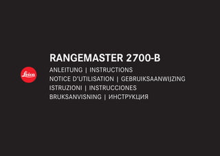
  • 1. RANGEMASTER 2700-B ANLEITUNG | INSTRUCTIONS NOTICE D’UTILISATION | GEBRUIKSAANWIJZING ISTRUZIONI | INSTRUCCIONES BRUKSANVISNING | ИНСТРУКЦИЯ RANGEMASTER 2700-B ANLEITUNG | INSTRUCTIONS NOTICE D’UTILISATION | GEBRUIKSAANWIJZING ISTRUZIONI | INSTRUCCIONES BRUKSANVISNING | ИНСТРУКЦИЯ
  • 3. RANGEMASTER 2700-B ANLEITUNG | INSTRUCTIONS NOTICE D’UTILISATION | GEBRUIKSAANWIJZING ISTRUZIONI | INSTRUCCIONES BRUKSANVISNING
  • 4. DE 2 3 4 5 6 4 7 11 8 9 Dieses Produkt wird hergestellt unter Lizenz von Leupold & Stevens, Inc. 10 1 2 3a
  • 5. DE 3 BEZEICHNUNG DER TEILE 1 Nebentaste 2 Haupttaste 3 Augenmuschel mit a. Dioptrienskala 4 Öse für Trageschnur 5 Okular 6 Batteriefachdeckel 7 Batteriefach 8 Objektivlinse 9 Abdeckkappe über Speicherkartenschacht 10 Speicherkartenschacht (Abdeckkappe geöffnet) 11 Laser-Sendeoptik
  • 6. DE 4 LASER-SICHERHEITSHINWEISE Im Leica Rangemaster wird ein unsichtbarer Laser- strahl eingesetzt. Stellen Sie sicher, das Folgende zu beachten: WARNUNG: Nichtbeachtung folgender Punkte kann zu schweren Verletzungen oder zum Tod führen. • Werden andere als die in dieser Anleitung aufge- führten Bedienungsvorgänge verwendet, bzw. Anpassungen am Gerät vorgenommen, kann es zum Austritt gefährlicher Strahlung kommen. • So lange Sie die Anzeige im Okular sehen ist das Produkt aktiv, sendet einen unsichtbaren Laser- strahl aus und die Laser-Fokussieroptik darf nicht auf jemanden gerichtet sein. • Demontieren oder verändern Sie den Leica Rangemaster nicht; wenn die interne Elektronik freigelegt wird, kann dies zu Schäden oder Stromschlägen führen. • Drücken Sie keine der beiden Tasten, während Sie auf ein menschliches Auge zielen oder die Optik von der Objektivseite aus betrachten. • Bewahren Sie den Leica Rangemaster nicht in Reichweite von kleinen Kindern auf. VORSICHT: Nichtbeachtung folgender Punkte kann zu Verlet- zungen oder zur Beschädigung des Geräts führen. • Richten Sie den Laser nicht auf ein Auge. • Richten Sie den Laser nicht auf Menschen. • Betreiben Sie den Leica Rangemaster nicht mit anderen zusätzlichen optischen Elementen, wie Objektiven oder Ferngläsern. Eine Verwendung des Leica Rangemasters zusammen mit einem opti- schen Gerät erhöht die Gefahr einer Verletzung der Augen. • Wird die Entfernungsmessung gerade nicht benötigt, sollten Sie es vermeiden, eine der beiden Tasten zu betätigen, um ein unbeabsich- tigtes Abgeben des Laserstrahls zu vermeiden. • Entfernen Sie die Batterie aus dem Gehäuse, wenn Sie den Leica Rangemaster für längere Zeit nicht verwenden. • Sie dürfen den Leica Rangemaster nicht zerle- gen, neu zusammensetzen oder reparieren. Die ausgehende Laserstrahlung kann Ihre Gesund- heit gefährden. Ein einmal zerlegtes, neu zusam- mengesetztes oder repariertes Gerät unterliegt nicht mehr der Herstellergarantie.
  • 7. DE 5 • Ist das Gehäuse des Leica Rangemasters beschädigt oder gibt das Gerät nach einem Fall oder aus einem anderen Grund einen fremdarti- gen Ton ab, so entnehmen Sie bitte sofort die Batterie und verwenden ihn nicht mehr. TECHNISCHE DATEN DES LASERS Laserklasse IEC/EN Class 1 Wellenlänge (nm) 897 Pulsdauer (ns) 64 Ausgangsleistung (mW) 0,965 Strahlendivergenz (mrad) Vertikal: 1,28, Horizontal: 0,85 Das Produktionsdatum finden Sie auf den Aufkle- bern in der Garantiekarte und/oder auf der Verpa- ckung. Die Schreibweise des Datums ist: Jahr/Monat/Tag.
  • 8. DE 6 VORWORT Wir wünschen Ihnen viel Freude und Erfolg mit Ihrem neuen Leica Rangemaster. Dieser Entfer- nungsmesser sendet unsichtbare und für das Auge unschädliche Infrarot-Impulse aus und berechnet über einen eingebauten Mikroprozessor aus dem reflektierten Signalanteil die Objektentfernung. Darüber hinaus erfasst er Umgebungs- und Einsatz- bedingungen. Mit diesen ermittelt er – zusammen mit den gemessenen Entfernungen - entsprechende Korrekturen des Haltepunkts für verschiedene, wählbare Ballistik-Kurven und zeigt diese an. Er ist mit einer hervorragenden, 7fach vergrößernden Zieloptik ausgestattet, die auch unter schwierigen Bedingungen eine sichere Peilung ermöglicht. Darüber hinaus ist der Leica Rangemaster einfach und funktional zu bedienen. Damit Sie alle Möglich- keiten dieses hochwertigen und vielseitigen Laser- Entfernungsmessgerätes richtig nutzen können, empfehlen wir Ihnen, zunächst diese Anleitung zu lesen. Entsorgung elektrischer und elektronischer Geräte (Gilt für die EU sowie andere europäische Länder mit getrennten Sammelsystemen) Dieses Gerät enthält elektrische und/oder elektro- nische Bauteile und darf daher nicht im normalen Hausmüll entsorgt werden! Stattdessen muss es zwecks Recycling an entsprechenden, von den Gemeinden bereitgestellten Sammelstellen abgege- ben werden. Dies ist für Sie kostenlos. Falls das Gerät selbst wechselbare Batterien oder Akkus enthält, müssen diese vorher entnommen werden und ggf. Ihrerseits vorschriftsmäßig entsorgt wer- den (siehe dazu die Angaben in der Anleitung des Geräts). Weitere Informationen zum Thema bekom- men Sie bei Ihrer Gemeindeverwaltung, Ihrem Entsorgungsunternehmen, oder dem Geschäft, in dem Sie dieses Gerät erworben haben.
  • 9. DE 7 LIEFERUMFANG –– Entfernungsmesser –– 1 Lithium Rundzelle 3V Typ CR 2 –– Trageriemen –– microSD-Speicherkarte 8 GB –– microSD Karten-Adapter –– Corduratasche –– Garantiekarte –– Prüfzertifikat Warnhinweis Vermeiden Sie, wie bei jeder Optik, den direkten Blick mit Ihrem Leica Rangemaster in helle Lichtquellen, um Augenverlet- zungen auszuschließen.
  • 10. DE 8 INHALTSVERZEICHNIS Bezeichnung der Teile........................................... 3 Vorwort................................................................. 6 Lieferumfang......................................................... 7 Auswechseln der Batterie.................................... 10 Ladezustand der Batterie.................................... 10 Verwendung mit und ohne Brille.......................... 11 Dioptrien-Ausgleich............................................. 11 Grundsätzliches zur Menüsteuerung.................... 12 Einstellung der gewünschten Maßeinheit............. 12 Entfernungsmessung........................................... 13 Scan-Betrieb....................................................... 15 Messreichweite und Genauigkeit......................... 16 Anzeige der atmosphärischen Bedingungen......... 17 Bestimmen der Ballistik-Kurve............................. 18 Einstellen der Ballistik-Kurve................................ 19 Einstellen der Fleckschuss-Entfernung................. 20 Ballistische Ausgabeformate............................... 20 Einstellungen und Auswahl der ballistischen Ausgabeformate.............................. 21 Die äquivalente horizontale Entfernung................ 22 Der Haltepunkt................................................... 22 Treffpunktkorrektur mittels Elevationsverstellung......23 Anzeige und Überprüfung der eingestellten Ballistik-Parameter.......................... 23 Einsetzen beliebiger Ballistik-Kurven.................... 24 Was tun, wenn.................................................... 27 Technische Daten............................................... 28 Pflege/Reinigung................................................ 30 Ersatzteile........................................................... 30 Leica Service-Adressen....................................... 31 Anhang Ballistik-Tabellen............................................... 244
  • 11. DE 9 TRAGERIEMEN ANBRINGEN Bitte die kleine Schlaufe der Trageriemen durch die Öse 4 am Gehäuse des Leica Rangemaster schie- ben. Dann das Ende der Trageriemen durch die kleine Schlaufe fädeln und so festziehen, dass sich die entstandene Schlinge fest um die Öse am Gehäuse legt.
  • 12. DE 10 AUSWECHSELN DER BATTERIE Der Leica Rangemaster wird zur Energieversorgung mit einer 3 Volt Lithium-Rundzelle (z. B. Duracell DL CR2, Ucar CR2, Varta CR2, oder anderen CR2- Typen) bestückt. 1. Öffnen Sie den Deckel 6 des Batteriefachs 7, indem Sie ihn gegen den Uhrzeigersinn drehen. 2. Legen Sie die Batterie mit ihrem Pluskontakt voran (entsprechend der Kennzeichnung im Batteriefach) ein. 3. Schließen Sie den Deckel wieder durch Drehen im Uhrzeigersinn. Hinweise: • Kälte reduziert die Batterieleistung. Bei niedrigen Temperaturen sollte der Leica Rangemaster deshalb möglichst in Körpernähe getragen und mit einer frischen Batterie betrieben werden. • Wenn der Leica Rangemaster längere Zeit nicht benutzt wird, sollte die Batterie herausgenom- men werden. • Batterien sollten kühl und trocken gelagert werden. Achtung: • Batterien dürfen keinesfalls ins Feuer geworfen, erhitzt, wieder aufgeladen, zerlegt oder aufgebro- chen werden. • Verbrauchte Batterien dürfen nicht in den norma- len Hausmüll geworfen werden, denn sie enthal- ten giftige, die Umwelt belastende Substanzen. Um sie einem geregelten Recycling zuzuführen, sollten sie beim Handel abgegeben oder zum Sondermüll (Sammelstelle) gegeben werden. LADEZUSTAND DER BATTERIE Eine verbrauchte Batterie wird durch eine blinkende Messwert- und Zielmarkenanzeige signalisiert. Nach dem erstmaligen Blinken der Anzeige sind noch mehr als 100 Messungen mit fortschreitend verrin- gerter Reichweite möglich.
  • 13. DE 11 VERWENDUNG MIT UND OHNE BRILLE A B Beobachter, die keine Brille tragen, lassen die Gummi-Augenmuschel 3 hochgeklappt (Bild A, Lieferzustand). In dieser Position ist der richtige Abstand des Leica Rangemaster zum Auge gege- ben. Beim Beobachten mit Brille wird die Gummi- Augenmuschel umgestülpt (Bild B). DIOPTRIEN-AUSGLEICH Mit dem Dioptrien-Ausgleich können Sie die Schärfe der Zielmarke und der Anzeigen auf den für Sie optimalen Wert einstellen. Einfach durch den Leica Rangemaster ein weit entferntes Objekt anpeilen und durch Drehen an der Augenmuschel 3 die Zielmarke auf optimale Schärfe einstellen. Sie erscheint bei Druck auf die Haupttaste 2. Den eingestellten Wert können Sie an der Skala 3a auf der Augenmuschel ablesen. Ein Dioptrien-Ausgleich ist für Fehlsichtigkeiten bis ± 3,5 Dioptrien möglich.
  • 14. DE 12 GRUNDSÄTZLICHES ZUR MENÜSTEUERUNG Das Hauptmenü besteht aus den vier Menüpunk- ten: –– Meter-/Yard-Anzeige (EU.US) –– Ballistik-Kurve (bALL) –– Fleckschussentfernung (SId) –– ballistische Ausgabeformate (AbC) Einzelheiten zu den Funktionen finden sie in den jeweiligen Abschnitten. Grundsätzlich gilt: Sowohl das Hauptmenü als auch die jeweiligen Einstellungsoptionen der einzelnen Menüpunkte sind als Endlos-Schleifen geschaltet, d. h. alle Punkte/Einstellungen sind durch mehrfachen Tastendruck immer wieder zu erreichen. EINSTELLUNG DER GEWÜNSCHTEN MAßEINHEIT Der Leica Rangemaster kann auf das metrische oder imperiale Maßeinheitensystem eingestellt werden, d. h. für Entfernung/Temperatur/Luftdruck entweder Meter/Celsius/Millibar oder entspre- chend Yards/Fahrenheit/InHg (Inches of Mercury). Diese Einstellung bestimmt auch die Einheiten des Haltepunktes, der Ballistik-Kurven und der Fleckschuss-­Entfernungen. 1. Drücken Sie die Nebentaste 1 lang (≥ 3 s). • Es erscheint EU.US (blinkend). 2. Drücken Sie die Haupttaste 2, um die gewünschte Maßeinheit auszuwählen. US = für Anzeige in Yards EU = für Anzeige in Meter
  • 15. DE 13 Hinweis: Die jeweilige Einstellung ist stets an der Anzeige zu erkennen: Zusätzlich zu den Ziffern erscheint M (für Meter) oder Y (für Yards). 3. Speichern Sie Ihre Einstellung durch kurzes Drücken ( 2 s) der Nebentaste. • Die gespeicherte Einstellung leuchtet zur Bestätigung zunächst dauerhaft, anschlie- ßend wechselt die Anzeige zunächst zum nächsten Menüpunkt (Ballistik-Kurve bALL) und erlischt danach, sofern keine weiteren Einstellungen vorgenommen wurden.
  • 16. DE 14 ENTFERNUNGSMESSUNG 9 8 Um die Entfernung zu einem Objekt zu messen, muss es genau angepeilt werden. Gehen Sie dazu wie folgt vor: 1. Drücken Sie die Haupttaste 2. Das Gerät schaltet sich ein. • Die Zielmarke erscheint. Nach dem Loslassen der Haupttaste leuchtet die Zielmarke noch für ca. 6 Sekunden weiter. Wird sie gedrückt gehalten, leuchtet die Zielmarke perma- nent. 2. Peilen Sie das Objekt an, während die Ziel- marke leuchtet. 3. Drücken Sie erneut die Haupttaste. a. Die Zielmarke erlischt während der Messung kurzzeitig. b. Der Messwert wird angezeigt. Solange die Zielmarke noch leuchtet, kann jederzeit eine neue Messung durch erneuten Druck auf die Haupttaste gestartet werden. Es erscheint: - - -, wenn – die Objektentfernung weniger als 10 Meter beträgt, oder – die Reichweite überschritten wird, oder – das Objekt ungenügend reflektiert. Mit dem Erlöschen der Anzeige schaltet sich der Leica Rangemaster automatisch ab.
  • 17. DE 15 SCAN-BETRIEB 6 1 6 3 7 2 Mit dem Leica Rangemaster kann auch im Dauerbe- trieb (Scan-Betrieb) gemessen werden: Halten Sie die Haupttaste 2 bei der zweiten Betäti- gung gedrückt. Nach ca. 2,5 Sekunden schaltet sich das Gerät in den Scan-Betrieb und führt dann permanent Messungen durch. Zu erkennen ist dies an der wechselnden Anzeige. Nach jeweils ca. 0,5 Sekunden wird ein neuer Messwert ausge- geben. Der Scan-Betrieb ist besonders praktisch bei der Messung auf kleine und sich bewegende Ziele. Hinweise: • Im Scan-Betrieb wird der AbC-Korrekturwert (s. S. 15) erst nach der letzten Messung ange- zeigt. • Im Scan-Betrieb ist der Stromverbrauch aufgrund der permanenten Messungen höher als bei Einzelmessungen.
  • 18. DE 16 MESSREICHWEITE UND GENAUIGKEIT Die maximale Reichweite des Leica Rangemaster wird erreicht bei gut reflektierenden Zielobjekten und einer visuellen Sichtweite von etwa10 km. Hohe Reichweiten können sicherer gemessen bzw. erreicht werden, wenn der Leica Rangemaster entweder sehr ruhig gehalten und/oder aufgelegt wird. Die Messreichweite wird von folgenden Faktoren beeinflusst: Reichweite höher geringer Farbe weiß schwarz Winkel zum Objektiv senkrecht spitz Objektgröße groß klein Sonnenlicht wenig (bewölkt) viel (Mittagssonne) Atmosphärische Bedingungen klar dunstig Bei Sonnenschein und guter Sicht gelten folgende Reichweiten bzw. Genauigkeiten: Reichweite ca. 10 - 2500 m Genauigkeit –– 800 - 2500 m: ca. ± 0,5 % –– 400 - 800 m: ca. ± 2 m –– 200 – 400 m: ca. ± 1 m –– 10 – 200 m: ca. ± 0,5 m Hinweis: Entfernungen unterhalb von 200 m werden ein- schließlich einer Dezimalstelle angezeigt, z. B. 164.5.
  • 19. DE 17 ANZEIGE DER ATMOSPHÄRISCHEN BEDINGUNGEN 1 5 6 3 C 1 0 3 0 Für die genaue Berechnung der Treffpunktlage (siehe dazu den folgenden Abschnitt) ermittelt der Leica Rangemaster während der Entfernungsmes- sung zusätzlich drei wichtige Zusatzinformationen: – die Neigung des Geräts – die Temperatur – den Luftdruck. Die jeweiligen Werte können Sie sich jederzeit anzeigen lassen. Drücken Sie die Nebentaste 1 1x kurz. • Die Zielmarke erscheint kurzzeitig (falls nicht vorher bereits die Entfernungsmessung einge- schaltet war). Anschließend erscheinen statt der Entfernung für jeweils ca. 2 s nacheinander – der Neigungswinkel (durch zusätzliches Winkel-Symbol gekennzeichnet) – die Temperatur – der Luftdruck Hinweis: Wenn das Gehäuse des Leica Rangemaster, bei- spielsweise beim Übergang von Innenräumen nach draußen, eine deutlich von der Umgebung abwei- chende Temperatur aufweist, kann es bis zu 30 min dauern, bis der innen liegende Messfühler wieder die korrekte Umgebungstemperatur anzeigt.
  • 20. DE 18 BESTIMMEN DER BALLISTIK-KURVE Zur präzisen Bestimmung der Treffpunktkorrektur bezieht der Leica Rangemaster die Geschossflug- bahn auf Grundlage des verwendeten Kalibers sowie Geschossart und -gewicht in die Berechnung mit ein. Dies beinhaltet auf Wunsch die Anpassung der Berechnung der äquivalenten horizontalen Entfernung (EHr, s. S. 21), des Haltepunkts (HOLd, s. S. 22) oder der Absehen-Verstellung (1/1-4/1- 3/10/5, s. S. 22). Zu dem Zweck stehen Ihnen 12 unterschiedliche, fest programmierte Ballistik-Kur- ven zur Auswahl. Suchen Sie in der Tabelle im Anhang, die der eingestellten Fleckschuss-Entfer- nung entspricht, die Ballistik-Kurve, die den Anga- ben des Munitionsherstellers zur Treffpunktlage am nächsten kommt. Beispiel: Das Zielfernrohr ist auf 100 m eingeschossen, es gilt also Tabelle 1. Als Treffpunktlage für die verwen- dete Munition wird -15,0 cm auf 200 m angegeben. In der entsprechenden Spalte entspricht das am ehesten dem Wert 14,5 cm in der Zeile EU7 – dies ist also die passende Ballistik-Kurve. Hinweis: Bei der Verwendung der Ballistik-Funktion des Leica Rangemaster auf größere Entfernungen als 300 m, und/oder beim Einsatz anderer, nicht durch die Geräteinternen Einstellungen abgedeckten Muniti- onsarten empfehlen wir Ihnen, entweder die ballisti- schen Daten Ihrer Munition durch praktische Versuche zu ermitteln, um die entsprechend pas- sende Kurve auswählen zu können, oder sie mit Hilfe des Leica Ballistik-Rechners zu ermitteln und per Speicherkarte auf das Gerät zu übertragen.
  • 21. DE 19 Einstellen der Ballistik-Kurve Beginnen Sie mit Schritt 1., wenn Sie die Menü- steuerung vorher noch nicht aufgerufen hatten, oder mit Schritt 3., wenn Sie vorher gerade die Maßeinheit eingestellt hatten und die Anzeige bAll noch blinkt. 1. Drücken Sie die Nebentaste 1 lang (≥ 3 s). • Es erscheint EU.US. 2. Drücken Sie die Nebentaste 1x kurz ( 2 s). • Die Anzeige wechselt zu den Ballistik-Kurven bALL. 3. Drücken Sie die Haupttaste 2. • Die Anzeige wechselt zu –– EU1 oder –– US1 Hinweis: Ist eine Speicherkarte eingesetzt (s. S. 25), erscheint CArd vor EU1 / US1. 4. Durch mehrfaches kurzes Drücken der Haupt- taste wählen Sie die gewünschte Ballistik- Kurve, d. h. –– EU1 bis EU12 oder US1 bis US12, bzw. –– OFF, wenn Sie die Entfernungsanzeige ohne Treffpunkt-Korrekturanzeige (AbC, s. S. 21 ff) wünschen. 5. Speichern Sie Ihre Einstellung durch kurzes Drücken der Nebentaste. • Die gespeicherte Einstellung leuchtet zur Bestätigung 4 s dauerhaft, anschließend wechselt die Anzeige zunächst zur Einstel- lung der Fleckschussentfernung (SId) und erlischt danach. Ist eine Ballistik-Kurve eingestellt, wird nach jeder Entfernungsmessung zunächst für 2 s der Entfer- nungswert angezeigt, danach für 6 s die errechne- ten Korrekturwerte.
  • 22. DE 20 EINSTELLEN DER FLECKSCHUSS- ENTFERNUNG (SId) Beginnen Sie mit Schritt 1., wenn Sie die Menü- steuerung vorher noch nicht aufgerufen hatten, mit Schritt 3., wenn Sie vorher gerade die Ballistik- Kurve festgelegt hatten und die Anzeige SId noch blinkt. 1. Drücken Sie die Nebentaste 1 lang (≥ 3 s). Es erscheint EU.US. 2. Drücken Sie die Nebentaste 2x kurz ( 2 s) Die Anzeige wechselt über bALL zu SId. 3. Durch mehrfaches Drücken der Haupttaste 2 wählen Sie die gewünschte Fleckschuss-Entfer- nung. –– 100 [m], –– 200 [m], oder –– GEE [m], bzw. –– 100 [y], oder –– 200 [y], oder –– 300 [y]. 4. Speichern Sie Ihre Einstellung durch kurzes Drücken der Nebentaste. • Die gespeicherte Einstellung leuchtet zur Bestätigung 4 s dauerhaft, anschließend wechselt die Anzeige zunächst zu AbC und erlischt danach. BALLISTISCHE AUSGABEFORMATE (AbCTM ) Die Advanced Ballistic Compensation (AbC) des Leica Rangemaster ermöglicht es Ihnen, sich im Anschluss an die gemessene Entfernung auf Wunsch einen der folgenden drei ballistischen Werte anzeigen zu lassen: –– die äquivalente horizontale Entfernung (EHr) –– den entsprechenden Haltepunkt (HOLd) –– die Anzahl der erforderlichen Klicks an der Absehen-Schnellverstellung (MOA/Klicks) Sowohl der angezeigte Haltepunkt als auch der angezeigte EHr-Wert berücksichtigen: a. die gemessene Entfernung zum Ziel, b. den Neigungswinkel, c. die eingestellte Ballistik-Kurve, d. die gemessenen Temperatur- und Luftdruck- Werte e. die eingestellte Fleckschuss-Entfernung Hinweise: • Die Berechnung der genannten Werte beruht auf der jeweils eingestellten Ballistik-Kurve, d. h. diese muss vorher ausgewählt werden (s. S. 18).
  • 23. DE 21 • Ballistische Ausgabewerte werden aus Sicher- heitsgründen nur bis zu einer Entfernung von 800 m angegeben. Darüber hinaus wird nur die tatsächlich gemessene Entfernung angegeben. Wichtig: • Bitte beachten Sie, dass gerade bei großen Entfernungen der Einfluss aller ballistisch rele- vanten Einflussfaktoren deutlich zunimmt und es zu erheblichen Abweichungen kommen kann. Die angezeigten ballistischen Werte sind deshalb ausdrücklich als Hilfsmittel zu verstehen! • Unabhängig von der Nutzung dieser Information unterliegt die Einschätzung der jeweiligen jagdli- chen Situation Ihrer Verantwortung! EINSTELLUNGEN UND AUSWAHL DER BALLISTISCHEN AUSGABEFORMATE Beginnen Sie mit Schritt 1, wenn Sie die Menüsteu- erung vorher noch nicht aufgerufen hatten, mit Schritt 3., wenn Sie vorher gerade die Fleckschuss- Entfernung eingestellt hatten und die Anzeige ABC noch blinkt. 1. Drücken Sie die Nebentaste 1 lang (≥ 3 s). • Es erscheint EUUS. 2. Drücken Sie die Nebentaste 3x kurz ( 2 s) • Die Anzeige wechselt über bALL und SId zu AbC. • 3. Durch mehrfaches Drücken der Haupttaste 2 wählen Sie die gewünschte ballistische Einstel- lung. –– EHr, oder –– HOLd, oder –– 1 (1 MOA), (Anzeige in Dezimal) –– 1-4 (1⁄4 MOA), bzw. –– 1-3 (1⁄3 MOA), bzw. –– 10 mm, bzw. –– 5 mm. 4. Speichern Sie Ihre Einstellung durch kurzes Drücken der Nebentaste. • Die gespeicherte Einstellung leuchtet zur Bestätigung 4 s dauerhaft, anschließend erlischt die Anzeige.
  • 24. DE 22 DIE ÄQUIVALENTE HORIZONTALE ENTFERNUNG (EHr) Schüsse auf höher oder tiefer gelegene Ziele unterliegen veränderten ballistischen Bedingungen. Sie erfordern daher die Kenntnis der - jagdlich relevanten - äquivalenten horizontalen Entfernung (Equivalent Horizontal Range). Die Kenntnis der EHr ist z. B. beim Einsatz von ballistischen Absehen wichtig. EHr-Werte werden durch die zusätzliche Anzeige gekennzeichnet. Hinweis: Auch horizontale EHr-Messungen können Werte ergeben, die von der „geradlinig“ gemessenen Entfernung abweichen, wenn beispielsweise die Temperatur und/oder der Luftdruck von den Normalwerten abweichen. DER HALTEPUNKT (HOLd) Als Haltepunkt wird derjenige Punkt bezeichnet, der anstatt des eigentlichen Zielpunkts mit der Waffe anvisiert wird, um die durch die Flugbahn des Geschosses verursachte Abweichung auszugleichen (z. B. bei der Verwendung klassischer jagdlicher Absehen). Durch die Anzeige des Haltepunkts kann der Leica Rangemaster im jagdlichen Einsatz wertvolle Unterstützung für das Anbringen mög- lichst präziser Schüsse leisten. Grundlage der Berechnung sind neben der Entfernung die im vorigen Abschnitt erwähnten Rahmenbedingungen und die von Ihnen gewählte Ballistik-Kurve. Hinweis: Jede angezeigte Schusskorrektur bezieht sich immer auf die Distanz zwischen dem Anwender und dem Ziel. Beispiel: Wird 300m und anschließend 30 angezeigt, müssten Sie auf dem Objekt 30 cm höher anhalten, als es ohne Korrektur der Fall wäre.
  • 25. DE 23 TREFFPUNKTKORREKTUR MITTELS ELEVATIONSVERSTELLUNG (Klick-/MoA- Verstellung) Abweichungen der Treffpunktlage können durch entsprechende Verstellung des Absehens an Ihrem Zielfernrohr ausgeglichen werden. Der Leica Range- master kann Ihnen – unter Berücksichtigung der Geschossflugbahn und der Fleckschuss-Entfernung (s. S. 20) - die dazu erforderliche Verstellung, d. h. die jeweilige Anzahl der Klicks anzeigen. Für verschiedene Elevationen können Sie dabei vorge- ben, ob die Klick-Stufen –– auf der Grundlage der international üblichen MOA-Einteilung (Minutes Of Angle), oder –– in 5- bzw. 10-Millimeter-Abstufungen ausgege- ben werden sollen. Anzeige und Überprüfung der eingestell- ten Ballistik-Parameter Wenn Sie Ihre Einstellungen überprüfen möchten, können Sie sich die Werte jederzeit anzeigen lassen: Drücken Sie die Nebentaste 1 2x kurz. • Unterhalb der Zielmarke erscheinen (ggf. statt der Entfernung) für jeweils ca. 2 s nacheinander –– die eingestellte Ballistik-Kurve (s. S. 18) –– die eingestellte Fleckschuss-Entfernung (s. S. 20) –– der eingestellte ballistische Ausgabewert (s. S. 21) Hinweis: Bei Abschaltung aller ballistischen Funktionen (bALL = OFF) wird dagegen EU oder US angezeigt.
  • 26. DE 24 EINSETZEN BELIEBIGER BALLISTIK-KURVEN Wenn die vorgesehene Waffen-/Geschoss-Kombi- nation nicht bereits durch eine der einprogrammier- ten Ballistik-Kurven EU1/US1- EU12/US12 abge- deckt ist, können Sie mit diesem Leica Rangemaster auch eigene, individuelle Ballistik-Kur- ven einsetzen. Dies erfolgt in vier Schritten: A. Einsetzen der Micro-SD-Speicherkarte in ein (mit dem Rechner verbundenes) Karten-Lesegerät mit Hilfe des mitge- lieferten SD-Kartenadapters microSD- Kartenadapter microSD- Speicherkarte B. Berechnung der gewünschten Ballistik- Kurve und Übertragen auf eine micro- SD-Speicherkarte Den Zugang zum Leica Ballistik-Rechner wie auch zur dazugehörigen Eingabemaske finden Sie auf der Seite des Leica Ballistikprogramms unter https://de.leica-camera.com/Sportoptik/ Leica-Jagdoptik/Leica-Ballistikprogramm.
  • 27. DE 25 C. Einsetzen/Herausnehmen der Speicherkarte in den/aus dem Leica Rangemaster D. Aufrufen der Ballistik-Kurve von der Speicherkarte Ist eine Speicherkarte in den Leica Rangemaster eingesetzt, auf der sich eine Ballistik-Kurve befindet, kann diese aufgerufen werden wie unter „Einstellen der Ballistik-Kurve“ auf S. 19 beschrieben. • Nach Drücken der Haupttaste 2 erscheint in dem Fall als erstes CArd. Wenn anschließend eine Entfernungsmessung vorgenommen wird können folgende Warnhinweise erscheinen: – Err1, wenn das bALL-Menü aufgerufen wurde, anschließend aber die Speicher- karte entnommen wird bzw. bei defekten oder nicht lesbaren Karten. In dem Fall erlischt auch CArd. – Err2, wenn sich keine Ballistik-Kurve auf der Speicherkarte befindet – Err3, wenn die Ballistik-Kurve auf der Speicherkarte unkorrekte Daten enthält. Die weitere Vorgehensweise entspricht genau der für die fest einprogrammierten Ballistik-Kurven. Fortsetzung nächste Seite.
  • 28. DE 26 Hinweise: • Berühren Sie die Kontakte der Speicherkarte nicht. • Falls sich die Speicherkarte nicht einsetzen lässt, überprüfen Sie ihre korrekte Ausrichtung. • Das Angebot an Micro-SD-Karten ist zu groß, als dass die Leica Camera AG sämtliche erhältlichen Typen vollständig auf Kompatibilität und Qualität prüfen könnte. Eine Beschädigung von Entfer- nungsmesser oder Karte ist zwar in aller Regel nicht zu erwarten, da jedoch insbesondere sogenannte no-name-Karten teilweise nicht die Micro-SD-Standards einhalten, kann die Leica Camera AG keine Funktionsgarantie überneh- men. • Aus Sicherheitsgründen, d. h. um Verwechslun- gen auszuschließen, kann immer nur eine ballisti- sche Kurve auf einer Karte gespeichert werden. Aus dem gleichen Grund wird eine Datei nicht erkannt, deren Name Sie verändert haben. • Bei der Verwendung von Ballistik-Kurven von der Speicherkarte werden Entfernungen bis 925 m angezeigt. • Auch wenn eine Speicherkarte eingesetzt ist, kann jederzeit eine der fest einprogrammierten Ballistik-Kurven eingestellt werden. Bitte überprü- fen Sie also immer Ihre Einstellungen
  • 29. DE 27 WAS TUN, WENN ... Fehler Ursache Abhilfe Bei der Beobachtung wird kein kreisrundes Bild erreicht. a) Pupille des Beobachters liegt nicht in der Austrittspupille des Okulars. b) Stellung der Augenmuschel entspricht nicht der richtigen Benutzung mit und ohne Brille. a) Augenposition korrigieren. b) Anpassung korrigieren: Brillenträger kni- cken die Augenmuschel um; bei Beobach- tung ohne Brille bleibt sie hochgeklappt (s. S. 11). Anzeige unscharf Dioptrienausgleich nicht exakt Dioptrienausgleich erneut durchführen (s. S. 11) Bei der Entfernungsmessung erscheint die Anzeige „- - -“ a) Messbereich über- oder unterschritten b) Reflexionsgrad des Objekts unzureichend Angaben zum Messbereich berücksichtigen (s. S. 13) Anzeige blinkt oder keine Messung möglich Batterie verbraucht Batterie auswechseln (s. S. 10)
  • 30. DE 28 TECHNISCHE DATEN Gerätebezeichnung LEICA RANGEMASTER CRF 2700 - B Typ-Nr. 5630 Vergrößerung 7x Objektivdurchmesser 24 mm Austrittspupille 3,4 mm Dämmerungszahl 13 Geometrische Lichtstärke 11,8 Sehfeld (auf 1.000 m) 115,6 m Objektiver Sehwinkel 6,6° Austrittspupillen-Längsabstand 15 mm Prismenart Dachkant Vergütung auf Linsen auf Prismen High Durable Coating (HDC™) und Aqua-Dura Vergütung auf Außenlinsen Phasenkorrekturbelag P 40 Dioptrienausgleich ± 3,5 dpt. Brillenträgertauglich Ja, durch umstülpbare Gummi-Augenmuschel Entfernungsmessung Maximale Reichweite Äquivalente horizontale Entfernung Ballistische Ausgabewerte Mindestentfernung Messgenauigkeit Anzeige/Maßeinheit Maximale Messdauer Messmethoden ca. 2500 m ca. bis 1100 m ca. bis 800 m ca. 10 m 800 - 2500 m: ca. ± 0,5 %:/400 - 800 m: ca. ± 2 m/200 – 400 m: ca. ± 1 m/ 10 – 200 m: ca. ± 0,5 m LED mit 4 Ziffern plus Zusatzzeichen, wahlweise in Meter/Zentimeter, bzw. yards/inches ca. 0,3 s Einzelmessung, Scanbetrieb
  • 31. DE 29 Laser Laserstrahl-Divergenz Unsichtbar, augensicher nach EN und FDA Klasse 1 ca. 0,5 x 1,2 mrad Gehäuse-/Chassismaterial Kohlefaser-verstärkter Kunststoff, softlackiert / Magnesium-Druckguss Schnittstellen Speicherkarte Schlitz mit Abdeckkappe für micro-SD-Speicherkarte, mitgelieferter SD-Kartenadapter erlaubt die Verwendung in SD-Kartenlesegeräten Wasserdichtigkeit Gehäuse Speicherkartenschacht Für 30 min: druckwasserdicht bis 1 m Wassertiefe Spritzwasser-geschützt Funktionstemperatur -20 bis 55 °C Lagertemperatur -40 bis 85 °C Batterie Lithium-Rundzelle 3V Typ CR2 Batterielebensdauer ca. 2.000 Messungen bei 20 °C Abmessungen (B x H x T) ca. 75 x 34 x 113 mm Gewicht (mit Batterie) ca. 185 g Änderungen in Konstruktion, Ausführung und Angebot vorbehalten.
  • 32. DE 30 PFLEGE/REINIGUNG Eine besondere Pflege Ihres Leica Rangemaster ist nicht notwendig. Grobe Schmutzteilchen, wie z. B. Sand sollten mit einem Haarpinsel entfernt oder weggeblasen werden. Fingerabdrücke u. Ä. auf Objektiv- und Okularlinsen können mit einem feuchten Tuch vorgereinigt und mit einem weichen, sauberen Leder oder staubfreien Tuch abgewischt werden. Wichtig: Üben Sie auch beim Abwischen stark verschmutzter Linsenoberflächen keinen großen Druck aus. Die Vergütung ist zwar sehr abriebfest; durch Sand oder Salzkristalle kann sie dennoch beschädigt werden. Das Gehäuse sollte nur mit einem feuchten Tuch ge- reinigt werden. Bei Verwendung von trockenen Tü- chern besteht die Gefahr der statischen Aufladung. Alkohol und andere chemische Lösungen dürfen nicht zur Reinigung der Linsen oder des Gehäuses verwendet werden. Jeder Leica Rangemaster trägt außer der Typbezeichnung seine „persönliche“ Fab- rikationsnummer. Notieren Sie sich diese Nummer zur Sicherheit in Ihren Unterlagen. Achtung: Das Gerät darf auf keinen Fall geöffnet werden! ERSATZTEILE Falls sie einmal Ersatzteile für Ihren Leica Range- master benötigen sollten, wie z. B. Augenmuschel oder Trageriemen, wenden Sie sich bitte an unseren Product Support-Abteilung (Adresse s. S. 31) oder Ihre Leica Landesvertretung (Adressen siehe Leica Camera AG Homepage). Anmerkungen zum Anhang: • In den Tabellen 1, 2 und 3 sind die Entfernungen in Metern, die Geschossabfall-Werte in Zentime- tern angegeben, in den Tabellen 4, 5 und 6 in Yards bzw. Inches. • Alle Werte gelten für: –– einen Luftdruck von 1013 mbar –– eine Temperatur von 20 °C –– horizontale Schüsse
  • 33. DE 31 LEICA PRODUCT SUPPORT Anwendungstechnische Fragen zu den Leica Pro- dukten beantwortet Ihnen schriftlich, telefonisch oder per E-Mail die Product Support-Abteilung der Leica Camera AG. Leica Camera AG Product Support / Software Support Am Leitz-Park 5 D-35578 Wetzlar Tel.: +49(0)6441-2080-111 /-108 Fax: +49(0)6441-2080-490 info@leica-camera.com / software-support@leica-camera.com LEICA CUSTOMER CARE Für die Wartung Ihrer Leica-Ausrüstung sowie in Schadensfällen stehen Ihnen die Customer Care- Abteilung der Leica Camera AG oder der Reparatur- dienst einer Leica-Landesvertretung zur Verfügung (Adressenliste siehe Leica Camera AG Homepage). Leica Camera AG Customer Care Am Leitz-Park 5 D-35578 Wetzlar Tel.: +49(0)6441-2080-189 Fax: +49(0)6441-2080-339 customer.care@leica-camera
  • 34. EN 32 3 4 5 6 4 7 11 8 9 This product is manufactured under license from Leupold Stevens, Inc. 10 1 2 3a
  • 35. EN 33 DESIGNATION OF PARTS 1 Secondary button 2 Main button 3 Eyecup with a. Diopter scale 4 Eyelet for carrying strap 5 Eyepiece 6 Battery compartment cover 7 Battery compartment 8 Lens 9 Protection flap over memory card slot 10 Memory card slot (protection flap open) 11 Laser transmission lens
  • 36. EN 34 WARNING This indication alerts you to the fact that any improper use ignoring the contents described herein can result in potential death or serious injury. CAUTION This indication alerts you to the fact that any improper use ignoring the contents described herein can result in potential injury or material loss. SAFETY PRECAUTIONS (Laser) The Leica Rangemaster uses an invisible laser beam. Be sure to observe the following: WARNING • Use of controls or adjustments or performance of procedures other than those specified herein may result in hazardous radiation exposure • When you see the display through the eyepiece, please be aware that the product is active and emitting an invisible laser and the laser aperture should not be pointed toward anyone • Do not take the product apart or modify the product in any way to expose internal electronics that might cause damage or electric shock • Do not depress any button while aiming at a human eye or while looking into the optics from the objec- tive side • Do not leave the Leica Rangemaster within the reach of small children CAUTION • Do not aim at the eye. • Do not point the laser at people. • Do not operate the unit with other additional optical elements, such as lenses or binoculars. Using an optical instrument together with the Leica Range- master increases the danger of damaging the eyes. • When not measuring, please keep your fingers away from any button to avoid accidentally emitting the laser beam. • When not in use for an extended period, please remove the battery from the body.
  • 37. EN 35 • Do not disassemble/remodel/repair the Leica Rangemaster. The emitting laser may be harmful to your health. A product that has been disassembled/ remodeled/repaired is not guaranteed by the manufacturer. • If the Leica Rangemaster’s body cover is damaged, or if it emits a strange sound due to dropping or some other cause, remove the battery immediately and stop using. Technical Data (Laser) Class IEC/EN Class 1 Wavelength (nm) 897 Pulse duration (ns) 64 Output (mW) 0,965 Beam divergence (mrad) Vertical: 1,28, Horizontal: 0,85 This product is in conformity with performance stan- dards for laser products under 21 CFR 1040, except with respect to those characteristics authorized by Variance Number FDA-2016-V-3483 effective Novem- ber 4, 2016 The production date can be found on the stickers in the Guarantee Card and/or on the packaging. The date is written as follows: Year/Month/Day
  • 38. EN 36 FOREWORD We wish you a great deal of enjoyment and every success with your new Leica Rangemaster. This rangefinder emits invisible infrared impulses that are not harmful to the viewer’s eyes and uses an integrated microprocessor to calculate the distance to an object from the reflected signal component. In addition, it registers ambient and situational parameters. With these - and the measured distance - it calculates the respective holdover values for different, selectable ballistic curves and displays them. It features an outstanding scope with 7x magnification, ensuring a reliable bearing even under difficult conditions. Plus, the Leica Rangemaster is easy to handle and operate. To ensure that you get the best out of this high-quality and versatile laser rangefinder, we recommend reading these instructions first. Disposal of electrical and electronic equipment (Applies within the EU, and for other Euro- pean countries with segregated waste collection systems) This device contains electrical and/or electronic components and must therefore not be disposed of in general household waste! Instead, it should be disposed of at a recycling collection point provided by the local authority. This costs you nothing. If the device contains standard or rechargeable batteries, these must be removed first and also be disposed of in line with relevant regulations (for details, refer to the instructions of your device) Further information on this issue is available from your local administration, your local waste collection company, or in the store where you purchased this device.
  • 39. EN 37 SCOPE OF DELIVERY –– Rangefinder –– 1 lithium battery 3V, type CR 2 –– Carrying strap –– microSD memory card 8 GB –– microSD card adapter –– Cordura case –– Guarantee Card –– Test certificate Warning note As with all binoculars, avoid looking directly at bright light sources with your Leica Range- master in order to avoid eye damage.
  • 40. EN 38 TABLE OF CONTENTS Designation of Parts..................................................33 Foreword..................................................................36 Scope of delivery......................................................37 Changing the battery.................................................40 Battery charge level..................................................40 Use with and without glasses....................................41 Diopter compensation...............................................41 Basic information on menu control............................42 Setting the unit of measure.......................................42 Distance measurement.............................................43 Scan mode...............................................................45 Measuring range and accuracy..................................46 Indication of atmospheric conditions.........................47 Determining the ballistic curve..................................48 Setting the ballistic curve..........................................49 Setting of zero-range distance...................................50 Ballistic output formats.............................................50 Settings and selection of ballistic output formats.......51 Equivalent horizontal distance...................................52 Holdover...................................................................52 Impact point correction using elevation adjustment........................................53 Displaying and checking the set ballistic parameters...................................................53 Use of any ballistic curves.........................................54 Troubleshooting........................................................56 Technical data..........................................................58 Care/cleaning..........................................................60 Spare parts...............................................................60 Appendix Ballistic Tables........................................................244
  • 41. EN 39 ATTACHING THE CARRYING STRAP Feed the small loop on the carrying strap through the eyelet 4 on the housing of the Leica Rangemaster. Then thread the end of the strap through the small loop and pull tight, so that the resulting loop is securely around the eyelet on the housing.
  • 42. EN 40 CHANGING THE BATTERY The Leica Rangemaster is powered by a cylindrical 3 Volt lithium cell (e.g. Duracell DL CR2, Ucar CR2, Varta CR2, or other CR2 types). 1. Open the cover 6 on the battery compartment 7 by turning it counter-clockwise. 2. Insert the battery so that the positive contact goes in first (as shown by the markings in the battery compartment). 3. Close the cover again by turning it clockwise. Notes: • Cold conditions impair the battery performance. At low temperatures the Leica Rangemaster should be kept as close to the body as possible and a new battery should be fitted. • If the Leica Rangemaster will not be used for a long period, the battery should be removed. • Batteries should be stored in a cool dry place. Attention: • Batteries should never be put in a fire, heated, recharged, taken to pieces or broken apart. • Used batteries may not be disposed of as normal, household waste as they contain toxic materials that are harmful to the environment. To ensure that they are properly recycled, they should be returned to the dealer or disposed of as special waste (at a collection point). BATTERY CHARGE LEVEL A used battery is indicated by a flashing measured value and reticule display. Once the display starts flashing, at least another 100 measurements are possible, with a gradually reducing range.
  • 43. EN 41 USE WITH AND WITHOUT GLASSES A B Users who do not wear glasses can leave the rubber eyecup 3 folded up (Figure A, as supplied). This position gives the correct distance between the Leica Rangemaster and the eye. When using the Leica Rangemaster with glasses, the rubber eyecup should be folded down (Figure B). DIOPTER COMPENSATION Diopter compensation enables you to adjust the sharpness of the reticule to the optimum value for you. Simply aim the Leica Rangemaster at a distant object and adjust the reticule until it has optimum sharpness by turning the eyecup 3. The reticule appears when you press the main button 2. You can read the set value on the “+” or “-” scale 3a on the eyecup. Diopter compensation is available for vision defects of up to ± 3.5 diopters.
  • 44. EN 42 BASIC INFORMATION ON MENU CONTROL The main menu is made up of four menu items: –– Meter/Yard Display (EU.US) –– Ballistic curve (bALL) –– Zeroing distance (SId) –– ballistic output formats (AbC) Details of the individual functions can be found in the relevant sections. Generally: Both the main menu and the setting options are set up as a continuous loop - i.e. all items/settings are accessible by continually pressing the button. SETTING THE UNIT OF MEASURE The Leica Rangemaster can be set to metric or imperial units of measure, i.e. for distance/temperature/ atmospheric pressure either meters/Celsius/millibar or yards/Fahrenheit/InHg (Inches of Mercury). This setting also determines the details of the holdover, the ballistic curves and the zeroing distance. 1. Press and hold the secondary button 1 (≥ 3 s). • EU.US appears (flashing). 2. Press the main button 2 to select the desired unit of measure. US = for display in yards EU = for display in meters
  • 45. EN 43 Note: The current setting can always be seen in the display: M (for meters) or Y (for yards) appears in addition to the digits display. 3. Save your setting by briefly pressing the second- ary button ( 2 s). • The saved setting is initially lit continuously as confirmation, then the display switches to the next item in the menu (ballistics curve „bALL“) and then disappears if no further settings have been made.
  • 46. EN 44 DISTANCE MEASUREMENT 9 8 To measure the distance to an object, you must aim directly at it. To do this, proceed as follows: 1. Press the main button 2. This switches on the device. • The reticule appears. When you release the main button, the reticule remains lit for around another 6 seconds. If you hold it down, the reticule remains lit continuously. 2. Aim at the object while the reticule is lit. 3. Press the main button again. a. The reticule disappears briefly during the mea- surement. b. The measured value is displayed. As long as the reticule remains lit, you can carry out another measurement at any time by pressing the main button again. - - - appears, if – the distance to the object is less than 10 yards, or – the range is exceeded, or – the object is not sufficiently reflective. When the display disappears, the Leica Rangemaster shuts down automatically.
  • 47. EN 45 SCAN MODE 6 1 6 3 7 2 The Leica Rangemaster can also be used for continu- ous measurements (scan mode): Press and hold the main button 2 at the 2nd press. After around 2.5 seconds, the device switches to scan mode and then carries out continuous measurements. This can be seen by a change in the display. Around every 0.5 seconds, a new measured value is shown. Scan mode is particularly useful for measuring the range to small or moving targets. Notes: • In scan mode, the AbC compensation value (see p. 45) is displayed after the last measurement. • Because of the continuous measurements, power consumption is greater in scan mode than for single measurements.
  • 48. EN 46 MEASURING RANGE AND ACCURACY The maximum range is achieved with highly reflective target objects and a visual range of sight of around 11000 yards. Long ranges can be reliably measured / achieved by holding the Leica Rangemaster very steadily and/or placing it on a solid surface. The measuring range is influenced by the following factors: Range longer shorter Color white black Angle to lens perpendicular acute Object size large small Sunlight low (cloudy) high (midday sun) Atmospheric conditions clear hazy In sunlight and with good vision, the following ranges and accuracies can be achieved: Range approx. 10-2500 m/ 11-2700 yds Accuracy –– 800 - 2500 m / 875 - 2700 yds: approx. ± 0.5% –– 400-800 m / 437-875 yds: approx. ± 2 yds –– 200-400 m / 219-437 yds: approx. ± 1 yd –– 10-200 m / 11-219 yds: approx. ± 0.5 m/yds Note: Distances below 200 m/219 yds are shown with an accuracy of one decimal place, e. g. 164.5
  • 49. EN 47 INDICATION OF ATMOSPHERIC CONDITIONS 1 5 6 3 C 1 0 3 0 To accurately calculate the impact point (see following section), the Leica Rangemaster also determines three crucial pieces of additional information when measur- ing the range: – the inclination of the unit – temperature – atmospheric pressure You can display the relevant values at any time. Press the secondary button 1 briefly 1x. • The reticule appears briefly (if distance measure- ment was not previously activated) and then the following items appear in succession for around 2 s each instead of the range: – inclination (indicated by an additional angle symbol) – temperature – atmospheric pressure Note: If the housing of the Leica Rangemaster initially has a significantly different temperature than the surround- ings, for example when moving from inside to outside, it can take up to 30 minutes before the internal sensor can display the correct ambient temperature again.
  • 50. EN 48 DETERMINING THE BALLISTIC CURVE For the precise determination of the impact point correction, the Leica Rangemaster includes the bullet trajectory on the basis of the used caliber, as well as the bullet type and weight in the calculation. This includes the adjustment of the calculation of the equivalent horizontal distance (EHr, see p. 51) of the holdover (HOLd, see p. 22 ) or the sight adjustment (1/1-4/1-3/10/5, see p. 52) on request. Twelve different ballistic curves are available for adaptation to the equipment you are using. From the appropriate table in the appendix, find the ballistic curve that is closest to the bullet drop specified by the ammunition manufacturer. Make sure you choose the appropriate down range distance. Example: The rifle scope is zeroed to 100 meters, which means that Table 1 is applicable. The specified impact point for the ammunition used is -15.0 cm at 200 m. In the corresponding column, this is closest to the value 14.5 cm in row EU7 - this is therefore the appropriate ballistic curve. Note: When using the Leica Rangemaster’s ballistic function at distances longer than 330 m/yds and/or other ammunition types that are not covered by the internal settings of the device, we recommend to either deter- mine the ballistic data of your ammunition through practical testing to choose the appropriate curve, or to determine it with the Leica ballistics calculator and to transfer it by memory card to the device.
  • 51. EN 49 Setting the ballistic curve Start with step 1 if you have not previously opened the menu control, or with step 3 if you have just set the unit of measure and bAll is still flashing in the display. 1. Press and hold the secondary button 1 (≥ 3 s). • EU.US appears. 2. Press the secondary button briefly ( 2 s) once. • The display switches to the ballistic curves bALL. 3. Press the main button 2. • The display switches to –– EU1 or –– US1 Note: When a memory card is inserted (see p. ??), CArd appears before EU1 / US1. 4. By pressing the main button repeatedly, select the desired ballistic curve, i.e. –– EU1 to EU12 or US1 to US12, or –– OFF, if you want to have a distance display without point of impact settings display (AbC, see p. 51 ff). 5. Save your setting by briefly pressing the second- ary button. • The saved setting is initially lit continuously for 4 s as confirmation, then the display changes first to the zeroing distance setting (SId) and then disappears. If a ballistic curve is set, after each distance measure- ment the range value is first displayed for 2 s, then the calculated correction value for 6 s.
  • 52. EN 50 SETTING OF ZEROING DISTANCE (SId) Start with step 1 if you have not previously opened the menu control, or with step 3 if you have just set the unit of measure and SId is still flashing in the display. 1. Press and hold the secondary button 1 (≥ 3 s). EU.US appears. 2. Press the secondary button briefly ( 2 s) once. The display switches from bALL to SId. 3. By pressing the main button 2 repeatedly, select the desired down range distance. –– 100 [m], –– 200 [m] or –– GEE [m] or –– 100 [y] or –– 200 [y] or –– 300 [y]. 4. Save your setting by briefly pressing the second- ary button. • The saved setting is initially lit continuously for 4 s as confirmation, then the display switches to AbC and then disappears. BALLISTIC OUTPUT FORMATS (AbCTM ) The advanced ballistic compensation (AbC) on the Leica Rangemaster allows you to display one of the following three ballistic values after the measured range if required: –– the equivalent horizontal range (EHr) –– the corresponding holdover (HOLd) –– the number of clicks required on the rapid reticle adjustment (MOA/clicks) Both the displayed holdover and EHr values factor in: a. the measured range to the target b. the angle of inclination of the weapon c. the set ballistic curve d. the measured temperature and atmospheric pressure values e. the set zeroing distance Notes: • Calculation of the specified values is based on the currently set ballistic curve, i.e. the curve must be selected first (see p. 48). • For safety reasons, ballistic output values are only specified up to a range of 800 m/yds. The actual measured range is also specified.
  • 53. EN 51 Important: • Please note that particularly at long ranges, the influence of all relevant ballistic influencing factors is greatly increased and considerable variations can occur. The ballistic values displayed should there- fore only be viewed as a guideline. • Regardless of whether this information is used, you are responsible for assessing the relevant hunting situation. SETTINGS AND SELECTION OF BALLISTIC OUTPUT FORMATS Start with step 1 if you have not previously opened the menu control, or with step 3 if you have just set the down range distance and ABC is still flashing in the display. 1. Press and hold the secondary button 1 (≥ 3 s). • EUUS appears. 2. Press the secondary button briefly ( 2 s) once. • The display switches from bALL and SId to AbC. • 3. By pressing the main button 2 repeatedly, the desired ballistic setting is selected. –– EHr or –– HOLd or –– 1 (1 MOA), (display in decimal) –– 1-4 (1⁄4 MOA) or –– 1-3 (1⁄3 MOA) or –– 10 mm or –– 5 mm. 4. Save your setting by briefly pressing the second- ary button. • The saved setting is initially lit continuously for 4 s as confirmation, then the display disap- pears.
  • 54. EN 52 EQUIVALENT HORIZONTAL RANGE (EHr) Shots at targets at a higher or lower elevation are subject changed ballistic conditions. Therefore, they require knowledge of the equivalent horizontal range, which is relevant for hunting. Knowledge of the EHr is important when using ballistic reticles, for example. EHr values are indicated by the additional display . Note: Horizontal EHr measurements can also result in values that differ from the „straight line“ measured range, for example if the temperature and/or the atmospheric pressure vary from the normal values. HOLDOVER (HOLd) Holdover is defined as the point that you aim at with the weapon instead of the actual target point to compensate for the variation caused by the trajectory of the bullet (e.g. when using classic hunting reticles). By displaying the holdover, the Leica Rangemaster can provide valuable support in achieving the most accu- rate shots possible when hunting. In addition to the range, the calculation is based on the general condi- tions discussed in the previous section and the ballistic curve you have selected. Note: The holdover/elevation is always shown with reference to the range to the target. Example: If 300m 30 is displayed, you would have to aim 30 cm higher on the object than without correction.
  • 55. EN 53 IMPACT POINT CORRECTION USING ELE- VATION ADJUSTMENT (Click/MoA adjustment) Variations in the point of impact can be compensated by adjusting the reticle on your riflescope accordingly. Based on the bullet trajectory and the zeroin distance, the Leica Rangemaster can show you the required adjustment, i.e. the relevant number of clicks. For different elevations, you can specify whether the click levels will be –– based on the international standard MOA (min- utes of angle) graduation, or –– displayed in 5 or 10 millimeter increments. Displaying and checking the set ballistic parameters If you want to check your settings, you can display the values at any time. Press the secondary button 1 briefly 2x. • Below the reticule (instead of the range, if this was previously displayed), the following will appear in turn for around 2 s each: –– the set ballistic curve –– the set zeroing distance –– the set ballistic output value Note: When all ballistic functions are deactivated (bALL = OFF), only the OFF setting is displayed.
  • 56. EN 54 USE OF ANY BALLISTIC CURVES If the intended combination of weapon and ammunition is not already covered by one of the programmed ballistic curves EU1 / US1-EU12 / US12, you can also use your own, individual ballistic curves with the Leica Rangemaster. This is done in four steps: A. Insertion of the Micro-SD memory card in a card reader via the supplied SD card adapter (connected to a computer) microSD memory card adapter microSD memory card B. Calculation of the desired ballistic curve and transfer to the Micro-SD memory card Access to the Leica Ballistic Calculator as well as the respective entry mask can be found on the Leica Ballistic Program page under https://de.leica-camera.com/Sportoptik/Lei- ca-Jagdoptik/Leica-Ballistikprogramm
  • 57. EN 55 C. Inserting / Removing the memory card into / from the Leica Rangemaster D. Opening the ballistic curve from the memory card If a memory card with a ballistic curve is inserted into the Leica Rangemaster, it can be selected just as described under “Setting the ballistic curve” on p. 49. • After pressing the main button 2 CArd appears first in this case. If a distance measurement is subsequently performed, the following warning messages may appear: – Err1 if the bALL menu was selected, but the memory card is removed, defect or nonread- able. In this case, CArd also disappears. – Err2 if there is no ballistic curve on the memory card. – Err3 if the ballistic curve on the memory card does not contain correct data. The following procedure corresponds to the one for the programmed ballistic curves. Continued on next page.
  • 58. EN 56 Notes: • Do not touch the memory card contacts. • If the memory card cannot be inserted, check that it is aligned correctly. • The range of available microSD memory cards is too large for Leica Camera AG to be able to completely test all available types for compatibility and quality. Although no damage to the rangefinder or the card is generally expected, because some so-called no name cards may not fully comply with the microSD standards Leica Camera AG cannot provide any guarantee of function. • For safety reasons, that is to avoid confusion, only one ballistic curve can be saved on a card. For the same reason, a file will not be recognized if you change its name. • When using ballistic curves from the memory card, distances of up to 925 m/1000 y will be displayed. • Even though a memory card is inserted, one of the programmed ballistic curves can be selected at any time. Hence, please always check your settings.
  • 59. EN 57 TROUBLESHOOTING Problem Cause Remedy The image seen viewing through the binoculars is not perfectly circular. a) Your pupil is not in line with the exit pupil of the eyepiece. b) Eyecup setting not correct for use with/ without glasses. a) Adjust eye-to-eyepiece alignment c) Adjust the settngs: Wearer of glasses fold the eyecup back; in case of use without glasses, the eyecup remains folded out (s. p. 41). Diplay blurred Diopter setting incorrect Repeat diopter adjustment (see p. 41) When attempting a measurement, the display„- - -“ appears a) Minimum/maximum measuring range exceeded b) Target object’s reflectivity is insufficient Take the specified ranges into account (see p. 43) Display flashes or no measurement possible Battery exhausted Replace battery (see p. 40)
  • 60. EN 58 TECHNICAL DATA Designation LEICA RANGEMASTER CRF 2700 - B Type No. 5630 Magnification 7x Lens diameter 24 mm/15/16 in Exit pupil diameter 3.4 mm/9/64 in Twilight factor 13 Relative brightness 11.8 Field of view (at 1,000 m/yds) 115.6 m/yds Subjective viewing angle 6.6 ° Eye relief 15 mm/19/32 in Prism system Roof Coating on lenses on prisms High Durable Coating (HDC™) and Aqua-Dura coating on external lenses Phase correction coating P40 Diopter compensation ± 3.5 dpt. Suitable for use when wearing glasses Yes, with the help of the rubber eyecup which can be folded down Distance measurement Maximum range Equivalent horizontal distance Ballistic output values Minimum range Measuring accuracy Display/Unit of measure Maximum measurement duration Metering methods approx. 2500 m/2734 yds approx. to 1100 m/1203 yds approx. to 800 m/875 yds approx. 10 m/11 yds 800-2500 m / 875-2734 yds: approx. ± 0.5% / 400-800 m/ 437-875 yds: approx. ± 2 m/6ft 6 in / 200–400 m/219-437 yds: approx. ± 1 m/3ft 3 in / 10–200 m/11- 219 yd: ca. ± 0.5 m/ 1ft 7 in 4-digit LED with additional characters, choice of meters/centimeters or yards/inches approx. 0.3 s Single measurement, scan mode
  • 61. EN 59 Laser Laser beam divergence Invisible, safe for eyes in compliance with EN and FDA Class 1 approx. 0.5 x 1.2 mrad Body/chassis material Carbon fiber reinforced plastic, soft lacquered / cast magnesium Interfaces Memory cards Slot with cover for Micro-SD cards, supplied SD card adapter allows the use with SD card readers Waterproofing Body Memory card slot For 30 min: waterproof to 1 m/3 ft depth Splash water protected Operating temperature range -20 to 55°C / -4 to 130°F Storage temperature -40 to 85°C / -40 to 185°F Battery Cylindrical 3 V lithium cell, type CR2 Battery life approx. 2,000 measurements at 20°C/68°F Dimensions (W x H x D) approx. 75 x 34 x 113 mm / 2 61/64 x 1 11/32 x 4 29/64 inch Weight (with battery) approx. 185 g / 6.5 oz Subject to changes in design, production, and scope of delivery.
  • 62. EN 60 CARE/CLEANING Your Leica Rangemaster requires no special care. Coarse particles of dirt such as sand should be removed with a hair brush or blown away. Fingerprints or similar on objective and eyepiece lenses can be pre-cleaned with a damp cloth and then wiped off with a soft, clean chamois or dust-free cloth. Important: Do not exert excessive pressure, even when wiping very dirty lens surfaces. Although the coating is highly abrasion-resistant, it can nevertheless be damaged by sand or salt crystals. The housing should be cleaned only using a damp cloth. There is a risk of static charges if dry cloths are used. Alcohol and other chemical solutions must not be used to clean the lens surfaces or the housing. In addition to the designation by type, each Leica Range- master has an individual serial number. Please note this number in your documents as a safety measure. Attention: Never open the unit. SPARE PARTS Please contact the Leica Camera AG Product Support department (address see p. 31) or your national Leica representative (for address, see Leica Camera AG homepage) if you ever need spare parts for your Leica Rangemaster like an eyecup or a carrying strap. Comments: • Tables 1, 2 and 3 show the ranges in meters and the holdover corrections in centimeters, while tables 4 and 5 use yards and inches. • All values are applicable for: –– a barometric pressure of 1013 mbar –– a temperature of 20°C/68°F –– horizontal shots
  • 63. EN 61 LEICA PRODUCT SUPPORT The Leica Camera AG Product Support department can provide you with an answer to any technical application questions relating to the Leica products either in writing, on the telephone or by e-mail. Leica Camera AG Product Support / Software Support Am Leitz-Park 5 35578 Wetzlar, Germany Tel.: +49(0)6441-2080-111 /-108 Fax: +49(0)6441-2080-490 info@leica-camera.com / software-support@leica-camera.com LEICA CUSTOMER CARE The Leica Camera AG Customer Care department or the repair service provided by authorized Leica agents in your country are available for service, maintenance and repairs of your Leica equipment (see the Leica Camera AG homepage for a list of addresses). Leica Camera AG Customer Care Am Leitz-Park 5 35578 Wetzlar, Germany Tel.: +49(0)6441-2080-189 Fax: +49(0)6441-2080-339 customer.care@leica-camera
  • 64. EN 62 FOR US ONLY FCC Note: This equipment has been tested and found to comply with the limits for a Class B digital device, pursuant to Part 15 of the FCC Rules. These limits are designed to provide reasonable protection against harmful interfer­ ence in a residential installation. This equipment generates, uses, and can radiate radio frequency energy and, if not installed and used in accordance with the instructions, may cause harmful interference to radio communications. However, there is no guar­ antee that interference will not occur in a particular installation. If this equipment does cause harmful interference to radio or television reception, which can be determined by turning the equipment off and on, the user is encouraged to try to correct the interfer- ence by one or more of the following measures: • Reorient or relocate the receiving antenna. • Increase the separation between the equipment and receiver. • Connect the equipment into an outlet on a circuit different from that to which the receiver is con- nected. • Consult the dealer or an experienced radio/TV technician for help. FCC Caution: To assure continued compliance, follow the attached installation instructions and use only shielded inter­face cables with ferrite core when connecting to com­put­er or peripheral devices. Any changes or modifications not expressly approved by the party responsible for compliance could void the user’s authority to operate this equipment. Trade Name: LEICA Type No. 5630 Responsible party/ Support contact: Leica Camera Inc. 1 Pearl Count, Unit A, Allendale, New Jersey 07401 Tel.: +1 201 995 0051/ Fax: +1 201 995 1684 technicalinfo@leicacamerausa.com
  • 65. EN 63 This device complies with Part 15 of the FCC Rules. Operation is subject to the following two conditions: (1) This device may not cause harmful interference, and (2) this device must accept any interference received, including interference that may cause undesired operation. Type No.: 5630 Tested To Comply With FCC Standards FOR HOME OR OFFICE USE For Canada only: CAN ICES-3 (B)/NMB-3(B)
  • 66. FR 64 3 4 5 6 4 7 11 8 9 Ce produit est fabriqué sous licence Leupold Stevens, Inc. 10 1 2 3a
  • 67. FR 65 DÉSIGNATION DES PIÈCES 1 Bouton auxiliaire 2 Bouton principal 3 Bonnette avec a. Graduation dioptrique 4 Œillet pour le cordon de port 5 Oculaire 6 Couvercle du compartiment à piles 7 Compartiment à piles 8 Lentille de l'objectif 9 Capuchon du compartiment de carte mémoire 10 Compartiment de carte mémoire (capuchon ouvert) 11 Optique d'émission laser
  • 68. FR 66 MISE EN GARDE Cette remarque prévient que le non-respect des points concernés peut provoquer des blessures graves voire entraîner la mort. PRUDENCE Ce symbole indique que le non-respect du contenu ci-dessous peut entraîner des blessures ou des dégâts matériels. CONSIGNES DE SÉCURITÉ (laser) Le télémètre laser Rangemaster utilise un rayon laser invisible. Assurez-vous de respecter ce qui suit : MISE EN GARDE • L’utilisation de commandes, d’ajustements ou de procédés autres que ceux spécifiés ici peut entraî- ner l’émission d’un rayonnement dangereux. • Quand vous voyez cet affichage dans l’oculaire, le produit est activé, il émet un rayonnement laser invisible et l’orifice de sortie du laser ne doit pas être dirigé vers une personne • Ne démontez pas ce produit et ne le modifiez pas pour dégager le système électronique interne ; cela pourrait provoquer des dégâts ou des décharges électriques • N’appuyez pas sur la touche Rangemaster alors que vous pointez l’œil d’une personne ou que vous regardez le système optique côté objectif • Ne rangez pas le produit Rangemaster à portée de main des enfants
  • 69. FR 67 PRUDENCE • Ne pointez pas le laser en direction d’un œil. • Ne pointez pas le laser en direction d’une ou plusieurs personnes. • N’utilisez pas l’appareil avec d’autres éléments optiques complémentaires tels que des objectifs ou des jumelles. L’utilisation du télémètre laser Range- master en même temps qu’un appareil optique augmente les risques de blessures aux yeux. • Si une mesure de distance n’est pas spécialement nécessaire, ne vous approchez pas de la touche Rangemaster pour éviter l’émission involontaire du rayonnement laser. • Retirez les batteries du boîtier si vous n’utilisez pas l’appareil photo pendant une période prolongée. • N’essayez pas de démonter, de remonter ou de réparer le télémètre laser Rangemaster. Le rayonnement laser émis peut avoir des conséquences sur votre intégrité physique. Un produit ayant été démonté, remonté ou réparé ne bénéficie plus de la garantie du fabricant. • Si le cache du boîtier du télémètre est endommagé ou encore si l’appareil émet un son à la suite d’une chute ou pour toute autre raison, retirez immédiatement la batterie et n’utilisez plus le télémètre. Caractéristiques techniques (laser) Classe laser Class 1 IEC/EN Longueur d'ondes (nm) 897 Durée de pulsation (ns) 64 Puissance de sortie (W) 0,965 Divergence du rayonnement (mrad) Verticalement : 1,28 Horizontalement : 0,85 La date de fabrication de votre appareil photo figure sur un autocollant sur la carte de garantie ou sur l’emballage. Cette date est indiquée ainsi : année/mois/jour.
  • 70. FR 68 AVANT-PROPOS Nous espérons que vous prendrez grand plaisir à utiliser votre nouveau Leica Rangemaster. Ce télé- mètre envoie des impulsions infrarouge invisibles et inoffensives pour les yeux et calcule la distance par rapport à l'objet par l'intermédiaire d'un microproces- seur intégré utilisant la partie du signal réfléchie. Par ailleurs il enregistre les conditions ambiantes et les conditions d'utilisation. À l'aide de celles-ci, il déter- mine, grâce aux distances mesurées, les corrections nécessaires du point de mire pour différentes courbes balistiques disponibles et les affiche. Il est équipé d'une optique de visée remarquable d'un grossisse- ment x7 permettant un relèvement fiable même en conditions difficiles. Par ailleurs le Leica Rangemaster est d'une utilisation simple et fonctionnelle. Afin de pouvoir utiliser correctement toutes les possibilités de ce télémètre laser haut de gamme polyvalent, nous vous recommandons de commencer par lire la pré- sente notice. Élimination des appareils électriques ou électroniques (applicable dans l'UE ainsi que dans les autres pays européens possédant des systèmes de tri sélectif) Cet appareil contient des composants électriques et/ ou électroniques et ne doit donc pas être jeté dans les ordures ménagères ordinaires. Il doit au contraire être rapporté à un point de collecte adapté mis à disposi- tion par les communes pour y être recyclé. C'est gratuit pour vous. Si l'appareil contient des piles ou des batteries remplaçables, celles-ci doivent être préalablement retirées et, le cas échéant, éliminées séparément par vos soins conformément à la régle- mentation en vigueur (voir pour cela les indications du mode d’emploi de l’appareil). D'autres informations à ce sujet sont disponibles auprès de l'administration municipale, de la société de traitement des déchets ou du magasin dans lequel vous avez acheté le présent appareil.
  • 71. FR 69 LIVRAISON –– Télémètre –– 1 pile cylindrique au lithium 3V type CR2 –– Courroie de port –– Carte mémoire microSD 8 Go –– Adaptateur pour carte microSD –– Sac Cordura –– Carte de garantie –– Certificat de contrôle Avertissement Comme pour toutes les jumelles, évitez de regarder directement des sources de lumière intenses avec votre Leica Rangemaster pour éviter des lésions oculaires.
  • 72. FR 70 TABLE DES MATIÈRES Désignation des pièces.............................................65 Avant-propos............................................................68 Contenu livré............................................................69 Remplacement de la pile...........................................72 État de charge de la pile............................................72 Utilisation avec ou sans port de lunettes...................73 Compensation dioptrique..........................................73 Ce qu'il faut savoir sur la commande du menu...........74 Paramétrage de l'unité de mesure désirée.................74 Mesure de la distance...............................................75 Mode Scan...............................................................77 Portée de mesure et précision...................................78 Affichage des conditions atmosphériques..................79 Détermination de la courbe balistique.......................80 Réglage de la courbe balistique.................................81 Réglage de la distance du point de chute..................82 Formats d'affichage balistiques.................................82 Réglages et sélection des formats d'affichage balistiques..................................83 La distance horizontale équivalente...........................84 Le point de mire........................................................84 Correction du point d'impact par réglage de l'angle de hausse......................................................................85 Affichage et vérification des paramètres balistiques établis...................................85 Insertion d'une sélection de courbes balistiques..............................................86 Que faire si...............................................................89 Caractéristiques techniques......................................90 Entretien/Nettoyage.................................................92 Pièces de rechange...................................................92 Annexe Tableaux balistiques................................................244
  • 73. FR 71 MISE EN PLACE DE LA COURROIE DE PORT Introduire la petite boucle de la courroie de port dans l'œillet 4 du Leica Rangemaster. Faire passer ensuite l'extrémité du cordon de port dans la petite boucle, puis serrer de manière que le nœud coulant ainsi formé soit bien serré autour de l'œillet du boîtier.
  • 74. FR 72 REMPLACEMENT DE LA PILE Le Leica Rangemaster est équipé d'une pile cylindrique au lithium 3 volts (par ex. Duracell DL CR2, Ucar CR2, Varta CR2 ou d'un autre type CR2). 1. Ouvrez le couvercle 6 du compartiment de la pile 7 en le faisant tourner dans le sens inverse des aiguilles d'une montre. 2. Insérez la pile avec la borne « plus » vers l'avant (conformément au schéma figurant dans le compartiment de la pile). 3. Refermez le couvercle en le faisant tourner dans le sens des aiguilles d'une montre. Remarques : • Le froid réduit les performances de la pile. À basse température, il convient par conséquent d'utiliser le Leica Rangemaster le plus près possible du corps et de le faire fonctionner avec une pile récente. • Si le Leica Rangemaster reste inutilisé pendant une assez longue durée, il faut retirer la pile. • Les piles doivent être stockées dans un endroit frais et sec. Attention : • Ne jetez jamais les piles au feu, ne les chauffez pas, ne les rechargez pas, ne les ouvrez pas et ne les cassez pas. • Les piles usagées ne doivent pas être jetées avec les déchets domestiques, car elles contiennent des substances toxiques nocives pour l'environnement. Afin de les intégrer à un circuit de recyclage, il convient de les rapporter au magasin ou de les mettre dans les déchets spéciaux (point de col- lecte). ÉTAT DE CHARGE DE LA PILE Quand la pile est usagée, un clignotement de la cible et de la valeur mesurée le signale. Après le clignotement initial de l'affichage, il est encore possible d'effectuer plus de 100 mesures dont la portée se réduit progres- sivement.
  • 75. FR 73 UTILISATION AVEC OU SANS PORT DE LUNETTES A B Un observateur qui ne porte pas de lunettes laissera les bonnettes en caoutchouc 3 relevées (Ill. A, état à la livraison). Dans cette position, la distance entre le Leica Rangemaster et l'œil est idéale. Pour l'observa- tion avec des lunettes, rabattre les bonnettes en caoutchouc (Ill. B). COMPENSATION DIOPTRIQUE Grâce à la compensation dioptrique, vous pouvez régler la netteté du repère de visée et les affichages à la valeur optimale pour vous. Viser simplement un objet lointain avec le Leica Rangemaster, puis régler la netteté optimale pour le repère de visée en tournant la bonnette 3. Le repère de visée apparaît quand vous appuyez sur le bouton principal 2. Vous pouvez savoir la valeur de réglage sur l'échelle 3a de la bonnette. Une compensation dioptrique est possible jusqu'à ± 3,5 dioptries pour prendre en compte les troubles de la vue.
  • 76. FR 74 CE QU'IL FAUT SAVOIR SUR LA COMMANDE À PARTIR DU MENU Le menu principal comprend les quatre options sui- vantes : –– affichage mètres/yards (EU.US) –– courbe balistique (bALL) –– distance du point de chute (SId) –– formats d'affichage balistiques (AbC) Pour plus de détails, voir les paragraphes concernés. Principe de base : Le menu principal ainsi que les options de réglage concernées des différentes options du menu sont conçus comme des boucles sans fin, c'est-à-dire qu'il est possible de revenir à chaque point ou réglage en appuyant plusieurs fois sur les touches. PARAMÉTRAGE DE L'UNITÉ DE MESURE DÉSIRÉE Le Leica Rangemaster peut être paramétré avec le système d'unités de mesures métrique ou anglo-saxon, c'est-à-dire pour la distance, la température et la pression atmosphérique soit mètres / ° Celsius / millibars soit yards / ° Fahrenheit / InHg (pouces de mercure). Ce paramétrage détermine également les unités du point de mire, des courbes balistiques et de la distance du point de chute. 1. Appuyez sur le bouton auxiliaire 1 pendant un certain temps (≥ 3 s). • EU.US apparaît (clignotant). 2. Appuyez sur le bouton principal 2 pour sélection- ner l'unité de mesure désirée. US = pour l'affichage en yards EU = pour l'affichage en mètres
  • 77. FR 75 Remarque : Le paramètre choisi est toujours identifiable sur l'affichage : En plus des chiffres apparaît M (mètres) ou Y (yards). 3. Enregistrez votre paramétrage en appuyant brièvement ( 2 s) sur le bouton auxiliaire. • Le paramétrage enregistré reste d'abord allumé en permanence en guise de confirmation, puis l'option de menu suivante (courbe balistique bALL) s'affiche et s'éteint ensuite si aucun autre paramétrage n'est effectué.
  • 78. FR 76 MESURE DES DISTANCES 9 8 Pour mesurer la distance par rapport à un objet, vous devez le viser précisément. Pour cela, procédez comme suit : 1. Appuyez sur le bouton principal 2. L'appareil s'allume. • Le repère de visée apparaît. Lorsque vous relâchez le bouton principal, le repère de visée reste encore allumé pendant environ 6 secondes. Tant que vous appuyez sur le bouton principal, le repère de visée reste allumé. 2. Visez l'objet pendant que le repère de visée est allumé. 3. Appuyez une nouvelle fois sur le bouton principal. a. Le repère de visée s'éteint brièvement durant la mesure. b. La valeur mesurée s'affiche. Tant que le repère de visée est allumé, il est possible à tout moment de démarrer une nouvelle mesure en appuyant une nouvelle fois sur le bouton principal. - - - apparaît si – la distance de l'objet est inférieure à 10 mètres ou si – la portée est dépassée ou si – l'objet ne se réfléchit pas suffisamment. Lorsque l'affichage s'éteint, le Leica Rangemaster se désactive automatiquement.
  • 79. FR 77 MODE SCAN 6 1 6 3 7 2 Le Leica Rangemaster permet également d'effectuer des mesures en continu (mode Scan) : maintenez le bouton principal 2 enfoncé la seconde fois. Au bout d'environ 2,5 secondes, l'appareil passe en mode Scan et efffectue alors des mesures en permanence. Le changement régulier d'affichage en est la preuve. Au bout d'env. 0,5 seconde, une nouvelle valeur de mesure apparaît. Le mode Scan est particulièrement pratique pour les mesures concernant les cibles mobiles de petite taille. Remarques : • En mode Scan, la valeur corrective AbC (voir p. 77) s'affiche seulement après la dernière mesure. • En mode Scan, la consommation électrique est plus importante que lors de mesures ponctuelles du fait des mesures ininterrompues.
  • 80. FR 78 PORTÉE DE MESURE ET PRÉCISION La portée maximale du Leica Rangemaster est atteinte avec des objets cibles suffisamment réfléchissants et avec une visibilité d'environ 10 km. Il est possible d'atteindre, ou de mesurer de manière fiable, une portée importante si le Leica Rangemaster est tenu sans bouger ou s'il est posé. La portée de mesure est influencée par les facteurs suivants : Portée plus grande plus faible Couleur blanc noir Angle par rapport à l'objectif 90° aigu Taille de l'objet grande petite Lumière solaire faible (nuageux) intense (soleil de midi) Conditions atmosphériques dégagé couvert La précision ou la portée ci-dessous peut être obtenue par temps ensoleillé et avec une bonne visibilité : Portée env. 10 - 2 500 m Précision –– 800 - 2 500 m : env. ± 0,5 % –– 400 - 800 m : env. ± 2 m –– 200 - 400 m : env. ± 1 m –– 10 - 200 m : env. ± 0.5 m Remarque : Les distances inférieures à 200 m s'affichent avec une décimale, par ex. 164.5.
  • 81. FR 79 AFFICHAGE DES CONDITIONS ATMOSPHÉRIQUES 1 5 6 3 C 1 0 3 0 Pour le calcul précis du point d'impact (voir paragraphe suivant), le Leica Rangemaster fournit également, en même temps que la mesure de la distance, trois informations complémentaires importantes : – l'inclinaison de l'appareil – la température – la pression atmosphérique. Vous pouvez faire apparaître ces valeurs à tout moment. Appuyez brièvement 1 une fois sur le bouton auxiliaire. • Le repère de visée apparaît brièvement (si la mesure de la distance n'a pas déjà été activée auparavant). Ensuite s'affichent à la place de la distance pendant env. 2 s en alternance – l'angle d'inclinaison (signalé également par un symbole d'angle supplémentaire) – la température – la pression atmosphérique Remarque : Si le boîtier du Leica Rangemaster présente une température notablement différente de celle de son environnement, par exemple si on quitte un bâtiment pour aller à l'extérieur, cela peut prendre 30 min avant que la sonde de température interne indique à nouveau la valeur correcte de la température ambiante.
  • 82. FR 80 DÉTERMINATION DE LA COURBE BALISTIQUE Pour déterminer avec précision la correction du point d'impact, le Leica Rangemaster intègre pour le calcul la trajectoire du projectile en se basant sur le calibre utilisé ainsi que sur le type et le poids du projectile. Sur demande, il prend en compte l'ajustement du calcul de la distance horizontale équivalente (EHr, voir p. 83), du point de mire (HOLd, voir p. 22) ou du réglage du réticule (1/1-4/1-3/10/5, voir. p. 84). À cet effet, vous disposez de 12 courbes balistiques préprogram- mées différentes. Cherchez dans le tableau en annexe, qui correspond à la distance paramétrée du point de chute, la courbe balistique la plus proche des indica- tions du fabricant de munitions concernant la position du point d'impact. Exemple : La lunette de visée est réglée sur 100 m eingeschossen, donc se référer au Tableau 1. La position du point d'impact pour la munition utilisée est indiquée à 15,0 cm près pour 200 m. Dans la colonne correspondante, cela correspond plutôt à une valeur de 14,5 cm sur la ligne EU7 – il s'agit bien là de la courbe balistique appropriée. Remarque : En cas d'utilisation de la fonction balistique du Leica Rangemaster sur des distances supérieures à 300 m, et/ou d'emploi de types de munition non prévus dans les réglages internes de l'appareil, nous vous recom- mandons soit de déterminer les données balistiques de votre munition grâce à des essais pratiques afin de pouvoir sélectionner la courbe appropriée ou de les déterminer à l'aide du calculateur balistique Leica et de les transférer sur l'appareil grâce à la carte mémoire.
  • 83. FR 81 Réglage de la courbe balistique Commencez par l'étape 1, si vous n'avez pas encore accédé à la commande à partir du menu, ou par l'étape 3 si vous venez de paramétrer l'unité de mesure et si l'affichage bAll clignote toujours. 1. Appuyez sur le bouton auxiliaire 1 pendant un certain temps (≥ 3 s). • EU.US apparaît. 2. Appuyez brièvement 1 fois sur le bouton auxiliaire ( 2 s). • L'affichage indique alors bALL. 3. Appuyez sur le bouton principal 2. • L'affichage indique alors –– EU1 ou –– US1 Remarque : Si une carte mémoire est insérée (cf. p. 25), alors apparaît CArd avant EU1 / US1. 4. Appuyer plusieurs fois sur le bouton principal pour sélectionner la courbe balistique désirée, c'est-à- dire –– EU1 à EU12 ou US1 à US12, ou –– OFF si vous souhaitez un affichage de la dis- tance sans afficher la correction du point d'impact (AbC, voir p. 83 et suiv.). 5. Enregistrez votre paramétrage en appuyant brièvement sur le bouton auxiliaire. • Le paramétrage enregistré reste allumé pen- dant 4 s pour validation, puis l'affichage bascule ensuite sur le paramétrage de la distance par rapport au point de chute (SId), puis s'éteint. Si une courbe balistique est paramétrée, après chaque mesure de distance s'affiche d'abord pendant 2 s la valeur de la distance, puis pendant 6 s les valeurs de correction calculées.
  • 84. FR 82 PARAMÉTRAGE DE LA DISTANCE PAR RAPPORT AU POINT DE CHUTE (SId) Commencez par l'étape 1, si vous n'avez pas encore accédé à la commande à partir du menu, ou par l'étape 3 si vous venez de définir la courbe balistique et si l'affichage SId clignote toujours. 1. Appuyez sur le bouton auxiliaire 1 pendant un certain temps (≥ 3 s). EU.US apparaît. 2. Appuyez brièvement 2 fois sur le bouton auxiliaire ( 2 s). L'affichage passe de bALL à SId. 3. Si vous appuyez plusieurs fois sur le bouton principal 2, vous sélectionnerez le paramétrage du point de chute souhaité. –– 100 [m], –– 200 [m], ou –– GEE [m], ou bien –– 100 [y], ou –– 200 [y], ou –– 300 [y]. 4. Enregistrez votre paramétrage en appuyant brièvement sur le bouton auxiliaire. • Le paramétrage enregistré reste d'abord allumé un certain temps en guise de confirmation, puis l'affichage bascule d'abord sur AbC et s'éteint ensuite. FORMATS D'AFFICHAGE BALISTIQUES (ABCTM ) L'Advanced Ballistic Compensation (AbC) du Leica Rangemaster vous permet d'afficher ensuite sur demande l'une des trois valeurs balistiques ci-dessous concernant la distance mesurée : –– la distance horizontale équivalente (EHr) –– le point de mire correspondant (HOLd) –– le nombre de clics nécessaires au réglage rapide du réticule (MOA/Klicks) Tenir compte à la fois du point de mire affiché et de la valeur EHr également affichée : a. la distance mesurée par rapport à l'objectif, b. l'angle d'inclinaison de l'arme, c. la courbe balistique paramétrée, d. les valeurs mesurées de la température et de la pression atmosphérique, e. la distance paramétrée du point du chute. Remarques : • Le calcul des valeurs mentionnées repose sur la courbe balistique paramétrée, ce qui signifie que celle-ci doit être sélectionnée auparavant (voir p. 80). • Pour des raisons de sécurité, les valeurs d'affichage balistiques ne sont indiquées que pour une distance de 800 m. Par ailleurs seule la distance effective- ment mesurée est indiquée.
  • 85. FR 83 Important : • N'oubliez pas qu'à grande distance, l'influence de tous les facteurs pertinents d'un point de vue balistique augmente considérablement, ce qui peut entraîner des écarts. Les valeurs balistiques ffichées n'ont par conséquent qu'une valeur indicative. • Indépendamment de la prise en compte de cette information, l'évaluation de la situation de chasse concrète est de votre propre responsabilité ! RÉGLAGES ET SÉLECTION DES FORMATS D'AFFICHAGE BALISTIQUES Commencez par l'étape 1, si vous n'avez pas encore accédé à la commande à partir du menu, ou par l'étape 3 si vous venez de définir la distance par rapport au point de chute et si l'affichage ABC clignote toujours. 1. Appuyez sur le bouton auxiliaire 1 pendant un certain temps (≥ 3 s). • EUUS apparaît. 2. Appuyez brièvement 3 fois sur le bouton auxiliaire ( 2 s) • L'affichage bascule vers bALL et SId pour finir sur AbC. 3. Si vous appuyez plusieurs fois sur le bouton principal 2, vous sélectionnerez le paramétrage balistique souhaité. –– EHr, ou –– HOLd, ou –– 1 (1 MOA), (affichage avec décimales) –– 1-4 (1⁄4 MOA) ou –– 1-3 (1⁄3 MOA) ou –– 10 mm ou –– 5 mm. 4. Enregistrez votre paramétrage en appuyant brièvement sur le bouton auxiliaire. • Le réglage enregistré reste allumé pendant 4 s pour validation, puis l'affichage s'éteint.
  • 86. FR 84 DISTANCE HORIZONTALE ÉQUIVALENTE (EHr) Les tirs sur des cibles en hauteur ou en contrebas sont soumis à des conditions balistiques variables. Elles nécessitent par conséquent la connaissance de la distance horizontale équivalente (Equivalent Horizontal Range), importante pour la chasse. La connaissance de l'EHr est importante par ex. pour l'utilisation de réti- cules balistiques. Les valeurs EHr sont signalées par l'affichage complémentaire . Remarque : Même les mesures EHr horizontales peuvent donner des valeurs qui varient par rapport à la distance mesurée en ligne droite si, par exemple, la température et/ou la pression atmosphérique divergent par rapport aux valeurs normales. LE POINT DE MIRE (HOLd) On considère comme point de mire le point visé avec l'arme au lieu de la véritable cible afin de compenser la déviation due à la trajectoire du projectile (par ex. par l'utilisation de réticules classiques pour la chasse). Grâce à l'affichage du point de mire, le Leica Range- master peut, quand il est utilisé pour la chasse, consti- tuer une assistance précieuse pour la précision des tirs. Les bases sur lesquelles repose le calcul sont, en plus de la distance, les conditions générales mention- nées au paragraphe précédent ainsi que la courbe balistique que vous choisirez. Remarque : Le point de mire ou la valeur de la lunette de visée affiché est toujours indiqué en lien avec la distance par rapport à la cible. Exemple : Si l'affichage indique 300m puis 30, vous devez viser 30 cm plus haut que s'il n'y avait pas de correction.
  • 87. FR 85 CORRECTION DU POINT D'IMPACT PAR RÉGLAGE DE L'ANGLE DE HAUSSE (Réglage click/MoA) Les divergences du point d'impact peuvent être compensées par un réglage approprié du réticule de votre lunette de visée. Le Leica Rangemaster peut, en prenant en compte la trajectoire du projectile et la distance par rapport au point de chute, le réglage nécessaire pour cela, c'est-à-dire le nombre de clics. Pour différents angles de hausse, vous pouvez définir si les niveaux de clics doivent être établis selon la répartition MOA (Minutes of Angle) habituelle au plan international ou en incréments de 5 ou 10 mm. –– –– Affichage et vérification des paramètres balistiques établis Si vous voulez vérifier vos réglages, vous pouvez afficher leurs valeurs à tout moment. Appuyez brièvement 2 fois sur le bouton auxiliaire 1. • Sous le repère de visée apparaissent (le cas échéant au lieu de la distance) pendant env. 2 s en alternance –– la courbe balistique paramétrée, –– la distance paramétrée du point du chute. –– la valeur balistique de sortie paramétrée Remarque : En cas de déconnexion de toutes les fonctions balistiques (bALL = OFF), par contre seul l'affichage EU ou US apparaît.
  • 88. FR 86 INSERTION D'UNE SÉLECTION DE COURBES BALISTIQUES Si la combinaison arme/munition prévue n'est pas déjà représentée par l'une des courbes balistiques programmées EU1/US1 - EU12/US12, vous pouvez grâce au Leica Rangemaster également insérer vos propres courbes balistiques personnalisées. Ceci s'effectue en quatre étapes : A. Insertion de la carte mémoire micro SD dans un lecteur de cartes (raccordé au calculateur) à l'aide de l'adaptateur de carte SD fourni Adaptateur carte microSD Carte mémoire microSD B. Calcul de la courbe balistique souhai- tée et transfert sur une carte mémoire micro SD L'accès au calculateur balistique Leica ainsi qu'au masque d'écran de saisie correspondant est possible sur la page du programme balistique Leica sur le site https://de.leica-camera.com/Sportoptik/Lei- ca-Jagdoptik/Leica-Ballistikprogramm
  • 89. FR 87 C. Insertion/retrait de la carte mémoire dans le ou du Leica Rangemaster D. Accès à la courbe balistique à partir de la carte mémoire Si vous insérez une carte mémoire dans le Leica Rangemaster sur lequel se trouve une courbe balis- tique, celle-ci est accessible de la manière indiquée au paragraphe « Paramétrage de la courbe balistique » en p. 81. • Dans ce cas-là, CArd apparaît en premier lieu si vous appuyez sur le bouton principal 2. Si vous effectuez ensuite une mesure de la distance, les messages d'avertissement ci-dessous peuvent apparaître : – Err1, si vous êtes dans le menu bALL, mais si vous retirez ensuite la carte mémoire ou en cas de carte défectueuse ou illisible. Dans ce cas-là, CArd s'éteint aussi. – Err2, s'il n'y a pas de courbe balistique sur la carte mémoire. – Err3, si la courbe balistique sur la carte mémoire comporte des données incorrectes. La suite de la procédure est exactement la même que pour les courbes balistiques présentes en stock. Suite page suivante.
  • 90. FR 88 Remarques : • Ne touchez pas les contacts de la carte mémoire. • Si la carte mémoire ne s'insère pas correctement, vérifiez qu'elle est bien orientée. • Le nombre de modèles de carte micro-SD vendus dans le commerce est trop élevé pour que Leica Camera AG puisse contrôler la compatibilité et la qualité de toutes les cartes. Une détérioration du télémètre ou de la carte n'est généralement pas en cause ; toutefois, étant donné en particulier que certaines cartes dites sans marque ne présentent pas les standards micro-SD, Leica Camera AG décline toute responsabilité concernant le fonction- nement. • Pour des raisons de sécurité, c'est-à-dire pour éviter toute confusion, il n'est possible d'enregistrer qu'une seule courbe balistique sur une carte. Pour la même raison, un fichier dont vous avez modifié le nom ne sera pas reconnu. • Avec l'utilisation des courbes balistiques de la carte mémoire, les distances affichées peuvent aller jusqu'à 925 m. • Même si une carte mémoire est insérée, il reste toujours possible de paramétrer l'une des courbes balistiques en stock. Par conséquent vérifiez toujours vos paramétrages
  • 91. FR 89 QUE FAIRE SI... Défaut Cause Remède Pas d'image de forme ronde. a) La pupille de l'utilisateur ne correspond pas à la pupille de sortie de l'oculaire. b) La position des bonnettes n'est pas adaptée à une utilisation correcte avec ou sans port de lunettes. a) Corriger la position des yeux. b) Corriger l'adaptation : Les porteurs de lunettes rabattent les bonnettes ; en cas d'observation sans port de lunettes, elles restent relevées (vior p. 73). Affichage de mauvaise qualité Compensation dioptrique imprécise Effectuer une nouvelle compensation diop- trique (voir p. 73) Lors de la mesure de distance appa- raît l'affichage « - - - » a) Plage de mesure dépassée ou non atteinte b) Degré de réflexion de l'objet insuffisant Tenir compte des indications concernant la plage de mesure (voir p. 75) Affichage clignotant ou aucune mesure possible Batterie usagée Remplacer la batterie (voir p. 72)
  • 92. FR 90 CARACTÉRISTIQUES TECHNIQUES Dénomination de l'appareil LEICA RANGEMASTER CRF 2700 - B N° de type 5630 Agrandissement 7x Diamètre de l'objectif 24 mm Pupille de sortie 3,4 mm Indice crépusculaire 13 Luminosité géométrique 11,8 Champ de vision (à 1 000 m) 115,6 m Angle de vision objectif 6,6° Écart longitudinal de la pupille de sortie 15 mm Type de prisme En toit Traitement des lentilles des prismes Traitement High Durable Coating (HDC™) et Aqua-Dura sur les lentilles extérieures Couche de correction de phase P 40 Compensation dioptrique ± 3,5 dpt. Adapté aux porteurs de lunettes Oui, grâce aux bonnettes en caoutchouc rabattables Mesure de la distance Portée maximale Distance horizontale équivalente Valeur balistique de sortie Distance minimale Précision de mesure Affichage/unité de mesure Durée de mesure maximale Méthodes de mesure env. 2 500 m env. à 1 100 m env. à 800 m env. 10 m 800 - 2 500 m : env. ± 0,5 % : / 400 - 800 m : env. ± 2 m / 200 - 400 m : env. ± 1 m / 10 - 200 m : ca. ± 0,5 m LED avec 4 chiffres plus caractères supplémentaires, au choix en mètres/centimètres ou yards/pouces env. 0,3 s Mesure isolée, mode Scan
  • 93. FR 91 Laser Divergence faisceau laser Invisible, inoffensif pour les yeux selon les normes EN et FDA classe 1 env. 0,5 x 1,2 mrad Matière du boîtier/du châssis Matériau synthétique renforcé de fibres de carbone, peinture soft / magnésium moulé sous pression Interfaces Carte mémoire Fente avec capuchon de protection pour carte mémoire micro-SD, l'adaptateur de carte SD fourni permet l'utilisation dans les lecteurs de cartes SD Étanchéité Boîtier Compartiment de carte mémoire Durant 30 min : étanchéité à la pression de l'eau jusqu'à 1 m de profondeur Protection anti-projections Température de fonctionnement -20 à 55°C Température de stockage -40 à 85°C Pile Pile cylindrique au lithium 3V type CR2 Durée de vie de la pile env. 2 000 mesures à 20°C Dimensions (L x H x P) env. 75 x 34 x 113 mm Poids (avec la pile) env. 185 g Sous réserve de modifications concernant la conception, la réalisation et l'offre.
  • 94. FR 92 ENTRETIEN/NETTOYAGE Votre Leica Rangemaster ne nécessite pas d'entretien particulier. Enlever les particules grossières, telles que le sable, avec un pinceau fin ou en soufflant dessus. Les traces de doigts ou autres sur les lentilles d'objec- tif ou d'oculaire peuvent être d'abord nettoyées avec un chiffon humide, puis essuyées avec une peau de chamois douce et propre ou avec un chiffon non pelucheux. Important : N'exercez pas de pression importante sur la surface des lentilles quand vous les essuyez, même si elles sont très sales. Bien que le traitement antireflet soit résistant aux frottements, il peut être altéré par le sable ou les cristaux de sel. Nettoyez le boîtier uniquement avec un chiffon humide. En cas d'utilisation d'un chiffon sec, cela risque de provoquer de l'électricité statique. N'utilisez pas d'alcool ou autres solutions chimiques pour nettoyer les lentilles ou le boîtier. Chaque Leica Rangemaster présente, en plus de la désignation du type, un numéro de fabrication « personnel ». Par mesure de sécurité, notez ce numéro dans votre dossier. Attention : En aucun cas l'appareil ne doit être ouvert. REMPLACEMENT DES ACCESSOIRES S'il vous faut un jour des pièces de rechange pour votre Leica Rangemaster, par ex. des bonnettes ou une courroie de port, adressez-vous à notre service Pro- duct Support (adresse voir p. 31) ou à votre représen- tant national Leica (adresses : voir page d'accueil Leica Camera AG). Remarques concernant ce document annexe : • Les tableaux 1, 2 et 3 indiquent les distances en mètres et les valeurs de retombée en centimètres ; les tableaux 4, 5 et 6 les présentent en yards et en pouces. • Toutes les valeurs sont valables pour : –– une pression atmosphérique de 1 013 mbar –– une température de 20 °C –– des tirs à l'horizontale