The Series 500 Sample Coolers are our moderate capacity thermoelectric coolers. They provide a self-regulated 4.0°C dew point gas sample. The 500 Series Coolers condense the water from a wet gas sample with minimal loss of the water soluble gas fraction. To know more visit: https://www.universalanalyzers.com/products/gas-sample-coolers/500-series-cooler
500 Series Thermoelectric Gas Cooler | Universal Analyzers
1. 5200 Convair Drive • Carson City, NV 89706
+1 (775)883 2500 • sales.universal@ametek.com • www.universalanalyzers.com
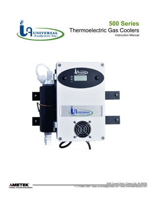
500 Series
Thermoelectric Gas Coolers
Instruction Manual
2. UA-MAN-500-20RF Page 2 of 20
TABLE OF CONTENTS
1.0 Receiving and Storage .......................................................................................... 3
2.0 Definition of Symbols............................................................................................. 4
3.0 Product Identification............................................................................................. 5
4.0 Specifications ........................................................................................................ 6
5.0 Description and Principle of Operation .................................................................. 8
6.0 Installation ........................................................................................................... 11
7.0 Start-Up............................................................................................................... 12
8.0 Shutdown ............................................................................................................ 13
9.0 Maintenance........................................................................................................ 14
10.0 Troubleshooting................................................................................................... 15
11.0 Drawings and Spare Parts................................................................................... 17
12.0 Standard Terms & Conditions of Sale and Warranty........................................... 18
3. UA-MAN-500-20RF Page 3 of 20
1.0 Receiving and Storage
The Universal Analyzers Series 500 Thermoelectric Gas Coolers are completely pre-assembled. No
assembly is necessary when received on-site.
Carefully inspect the product and any special accessories included with it immediately on arrival by
removing them from the packing and checking for missing articles against the packing list.
Check the items for any damage in transit and, if required, inform the shipping insurance company
immediately of any damage found.
Storage Location should be protected from the elements. Although all components provided are designed
to resist corrosion, additional protection from heat (>140°F/ 60°C) and humidity is recommended.
4. UA-MAN-500-20RF Page 4 of 20
2.0 Definition of Symbols
CAUTION, RISK OF DANGER SYMBOL INDICATES INJURY MAY OCCUR IF MANUFACTURER’S
INSTRUCTIONS ARE NOT ADHERED TO.
PLEASE READ MANUAL CAREFULLY WHEN SYMBOL IS DISPLAYED
CAUTION, HOT SURFACE SYMBOL INDICATES EXPOSED SURFACE TEMPERATURE CAN
CAUSE BURNS OR PERSONAL INJURY. CARE SHOULD BE TAKEN WHEN CONTACT IS
REQUIRED.
CAUTION, RISK OF ELECTRICAL SHOCK SYMBOL INDICATES ELECTRICAL SHOCK MAY
OCCUR. CAUTION SHOULD BE TAKEN BEFORE DISCONNECTING OR CONTACTING ANY
ELECTRICAL CONNECTIONS.
PROTECTIVE CONDUCTOR TERMINAL SYMBOL INDICATES THE TERMINAL LOCATION FOR
THE PROTECTIVE CONDUCTOR. FAILURE TO CONNECT TO THE PROTECTIVE CONDUCTOR
TERMINAL MAY RESULT IN A SHOCK HAZARD.
5. UA-MAN-500-20RF Page 5 of 20
3.0 Product Identification
For the current version of all Series 500 product configurations, visit the Universal Analyzers website.
https://www.universalanalyzers.com/
Navigate to: Products -> Gas Sample Coolers -> 500 Series Cooler
A link to the current configuration is provided at the bottom of the page.
6. UA-MAN-500-20RF Page 6 of 20
4.0 Specifications
OPERATING SPECIFICATIONS
Sample Flow Rate
Model 520 0 to 2 1/2 l/m total (at STP)
Model 530 0 to 5 l/m total (at STP)
Model 540 0 to 4 l/m total (at STP)
Model 560 0 to 5 l/m total (at STP)
Model 570 0 to 4 l/m total (at STP)
Model 574 0 to 4 l/m total (at STP)
Maximum Inlet Temperature
Stainless Steel Heat Exchanger 700°F (351°C)
Kynar/Glass Heat Exchanger 280°F (138°C)
Maximum Inlet Gas Dew Point 180°F (82°C)*
Maximum Inlet Water Concentration 50%*
Minimum Ambient Temperature 34°F (1°C)
Maximum Ambient Temperature 105°F (41°C)*
Maximum Cooling Power
Model 520 63 BTUs per hour (60 kJ/hr)
Model 530 63 BTUs per hour (60 kJ/hr)
Model 540 126 BTUs per hour (120 kJ/hr)
Model 560 126 BTUs per hour (120 kJ/hr)
Model 570 126 BTUs per hour (120 kJ/hr)
Model 574 126 BTUs per hour (120 kJ/hr)
Outlet Sample Dew Point 41°F (5°C)
Gas Sample Inlet Fitting 3/8" tubing fitting
Gas Sample Outlet Fitting 1/4" tubing fitting
Bottom Water Drain Fitting 3/8" tubing fitting
Maximum Input Power
Model 520 250 watts
Model 530 250 watts
Model 540 475 watts
Model 560 475 watts
Model 570 475 watts
Model 574 925 watts
Voltage
All models 90-132/180-264VAC, 50/60 Hz
Electrical Classification General Purpose, NEMA 1
Dimensions **
Model 520 11" H x 9" W x 9" D
Model 530 11" H x 11" W x 9" D
Model 540 11" H x 11" W x 10" D
Model 560 11" H x 9" W x 9" D
Model 570 11" H x 11" W x 10" D
Model 574 11" H x 11" W x 11" D
7. UA-MAN-500-20RF Page 7 of 20
Weight
Model 520 19 lbs (8.5 kg)
Model 530 21 lbs (9.5 kg)
Model 540 21 lbs (9.5 kg)
Model 560 21 lbs (9.5 kg)
Model 570 25 lbs (11.5 kg)
Model 574 25 lbs (11.5 kg)
Soluble Gas Removal Rates NO 0% loss
NO <10% loss
2
SO < 2% loss
2
CO 0% loss
CO < 2% loss
2
Storage Requirements Cool and dry location, -20°F < x < 120°F
< 95° relative humidity, non‐condensing
* AT REDUCED FLOW RATE ABOVE 77°F (25°C) AMBIENT
** DIMENSIONS DO NOT INCLUDE FITTINGS OR MOUNTING HARDWARE
8. UA-MAN-500-20RF Page 8 of 20
5.0 Description and Principle of Operation
APPLICATION
In order to accurately analyze combustion gases, moisture must be removed from the sample without
removing gas components of interest. The Universal Analyzers Thermoelectric Gas Cooler provides an
ideal repeatable, and stable way to decrease the dew point of combustion gasses. This prevents water
condensation in sample prefilters, sample pumps, and gas analyzers. Where water vapor is an
interferent, a stable and repeatable dew point becomes a part of the gas analyzer’s performance
specification. The 500 Series Cooler provides this constant, resulting in an accurate analysis of the gas
components of interest.
The gas sample is first pulled through a sample probe, which usually contains a heated filter, and then
through a heated sample line, which keeps the sample above its dew point. The 500 Series Cooler then
condenses water out of the sample, which lowers the dew point to 5°C (41°F).
The 500 Series Thermoelectric Gas Coolers are for general purpose, light duty applications. Several
models are available to meet various application conditions. Use the cooler selection chart below to best
fit a model to the expected flow rates, water vapor concentrations, and ambient temperature conditions. If
none of the models listed meet the needs of the application, contact your Universal Analyzers local sales
representative for more options.
GAS COOLER SELECTION CHART
Conditions Model
Ambient Water 520 530 540* 560 570 574* 574*
77°F
(25°C)
12% 2.5 l/m 4.0 l/m 2.5 l/m 5.0 l/m 4.0 l/m 5.0 l/m 2.5 l/m
15% 2.0 l/m 4.0 l/m 2.0 l/m 4.0 l/m 4.0 l/m 4.0 l/m 2.0 l/m
30% 1.0 l/m 4.0 l/m 1.0 l/m 2.0 l/m 4.0 l/m 2.0 l/m 1.0 l/m
50% 0.6 l/m 4.0 l/m 0.6 l/m 1.0 l/m 4.0 l/m 1.0 l/m 0.6 l/m
90°F
(32°C)
12% 2.0 l/m 3.0 l/m 2.0 l/m 4.0 l/m 3.0 l/m 4.0 l/m 2.0 l/m
15% 1.8 l/m 3.0 l/m 1.8 l/m 3.5 l/m 3.0 l/m 3.5 l/m 1.8 l/m
30% 0.9 l/m 3.0 l/m 0.9 l/m 1.8 l/m 3.0 l/m 1.8 l/m 0.9 l/m
50% 0.5 l/m 3.0 l/m 0.5 l/m 0.9 l/m 3.0 l/m 0.9 l/m 0.5 l/m
105°F
(41°C)
12% 1.5 l/m 2.0 l/m 1.5 l/m 3.0 l/m 2.0 l/m 3.0 l/m 1.5 l/m
15% 1.2 l/m 2.0 l/m 1.2 l/m 2.5 l/m 2.0 l/m 2.5 l/m 1.2 l/m
30% 0.6 l/m 2.0 l/m 0.6 l/m 1.3 l/m 2.0 l/m 1.3 l/m 0.6 l/m
50% 0.3 l/m 2.0 l/m 0.3 l/m 0.7 l/m 2.0 l/m 0.7 l/m 0.3 l/m
# of Gas Streams 1 1 2 1 2 2 4
*THE DATA PROVIDED IS FOR EACH STREAM
Various combustion processes can produce high levels of corrosive elements. An array of materials is
available for the 500 Series Coolers, where gases come into contact with heat exchangers. 316SS is the
most common option and meets the needs of most general-purpose applications. Coatings of Silconert™
2000, or Teflon® may be added to the stainless-steel heat exchanger to enhance chemical resistance.
Heat exchangers may also be made of other materials for corrosion resistance, such as Glass/Kynar®,
Kynar®/Kynar®, and Hastelloy® C276. Contact your local sales representative for information on which
material is best suited for your application.
9. UA-MAN-500-20RF Page 9 of 20
New Jersey Thermocouple Types K and J are available for external monitoring of heat exchanger
temperatures.
DESCRIPTION
The Universal Analyzers 500 Series Thermoelectric Gas Coolers condition gas sample streams to
remove water vapor. The gas sample is cooled thermoelectrically to a controlled temperature, and water
vapor is condensed and removed.
The key to success is being able to condense the water from a wet gas sample with a minimal loss of the
water-soluble gas fraction. The separation occurs in a classical impinger, which has a highly polished
cylindrical surface, cooled to the desired dew point temperature. The gas sample is brought to the bottom
of the cylinder through an insulated tube and allowed to rise through a narrow annular area at a relatively
high Reynolds number to insure the entire sample is influenced by the cold surface. The condensate falls
down the cold, polished surface in the form of a sheet (as opposed to droplets or the bubbling of the gas
sample through the condensate) which minimizes the surface area in contact with the gas sample.
The temperature of the cylindrical, condensation surface of the heat exchangers is maintained through
intimate contact with aluminum heat transfer blocks. The blocks are cooled with thermoelectric elements,
controlled to a temperature of 5°C. The temperature sensor is a type “K” thermocouple. The temperature
controller is proportional with a band of 1°C.
The fan cooled heat sink is constructed from anodized, pure aluminum fins which transfer heat to the
surrounding air. The pure aluminum material is a far better conductor of heat than the aluminum alloys
which are normally used for extruded heat sinks. The result is an assembly with superior heat exhausting
capabilities under high ambient temperature conditions.
The 500 Series Coolers have a digital display for front panel indication of the operating temperature of
each of the heat transfer blocks (switch selectable) in degrees Centigrade. Two internal jumpers at the
top of the control circuit board within the enclosure can be moved to change the indicated temperature to
read out in degrees Fahrenheit.
Three LED lamps to indicate the status of the cooler. The “COOL” lamp is a green LED which indicates
when the operating temperature has fallen below the factory set temperature of 10°C. An “Over-
temperature relay” is energized and closed to the cool position when the “COOL” lamp is on. The relay
board within the enclosure has dual terminal strip relay contacts for alarm/shutdown purposes. The
external gas sample pump may be interlocked with this relay to power off when temperatures become too
high (fail safe).
The “DRY” lamp is a green LED which indicates when there is no water in contact with the water carry-
over sensor (provided separately or as a system option). If no moisture sensor is used, the lamp may be
turned off by installing a jumper on the moisture sensor input terminals on the relay board. Without a
moisture sensor installed, the “DRY” lamp is always lit and does not indicate a condition. The moisture
sensor relay, which is energized in the “DRY” condition, provides contacts to an annunciator panel and/or
to turn off the sample pump in the “wet” condition.
The “TC” lamp is a red LED which indicates when there is a problem (open connection) in the
temperature control thermocouple. The “Over-temperature” relay will also transfer to the high temperature
condition if the red “TC” lamp comes on.
Universal Analyzers Sample Chillers are designed to interface with a condensate carry over sensor. The
standard sensor is provided with a filter (which is referred to as a “CCSF”) or it can be ordered without a
filter (“CCS”). This sensor is put in place as an early warning device to ensure that a clean, dry sample is
presented to the analyzer(s), thereby minimizing future maintenance and/or costly repairs. Condensate
sensor (CCS/CCSF) sold separately for 500/1000 series coolers.
The sensor is designed to operate with any current model Universal Analyzers sample chiller. If the
sensor needs to be used as a standalone device, then a 100A Moisture Detection Module must be used
in conjunction with the moisture sensor.
The technology behind the CCSF is a capacitive proximity sensor – this is advantageous because the
condensate does not need to be conductive to trigger an alarm. The sensor has an M12 connector on the
10. UA-MAN-500-20RF Page 10 of 20
bottom and uses the same one meter cable (Universal Analyzers Part No. 3907-1017) to interface
between the CCS/CCSF and all chillers and the 100A Moisture Detection Module. In addition, there is an
LED indicator on the sensor itself that illuminates upon detection of condensation or particulate.
LED INDICATOR CHART
LED Color Status Condition Relay Status
COOL Green
On Operating properly, temperature below 10°C Over Temperature: Energized, towards COLD
Off Temperature too high or unit is OFF Over Temperature: De-Energized, towards HOT
DRY Green
On CCS sensor connected, and sample is dry Condensate Sensor: Energized, towards DRY
Off Moisture detected, or jumper installed Condensate Sensor: De-Energized, towards WET
TC Red
On Temperature control TC has BAD quality Over temperature: De-Energized, towards HOT
Off Temperature control TC has OK quality Does not affect relays
A gas sample pump may be provided as part of the sampling system. If the pump is placed ahead of the
sample cooler, it should be provided with a heated head to avoid the condensation of water vapor. If the
sample pump is placed after the sample cooler, drawing the sample through the cooler, the sample has
been dried, and a standard, non-heated pump may be used.
A means to control the flow of the sample through the system should be available and visible to the
operator. This may be accomplished with pressure regulators and gauges, flowmeters, and/or flow control
needle valves.
Condensate removal from the heat exchanger(s) within the Sample Cooler can be accomplished through
one of the following methods:
1. A continuously running peristaltic tubing pump.
2. Installing the heat exchanger as a bypass condenser, pulling excess sample through with an eductor.
3. Using float drain traps similar to a steam trap. This requires the sample within the cooler to be at a
positive pressure.
4. Use of drain pots on level control with a removal pump.
11. UA-MAN-500-20RF Page 11 of 20
6.0 Installation
The 500 Series Thermoelectric Gas Coolers are best suited for Indoor, air-conditioned environments.
Each unit dissipates heat, and the surrounding area must be well ventilated to provide adequate cooling.
The cooler should be located away from other heat sources. If located inside a small enclosure, outside
air should be ducted directly onto the heat sink, and thermostatically controlled fans and vents should be
utilized. Never mount the unit in direct sunlight to avoid solar heat loading.
Route heated sample line directly to the 3/8” inlet tubing fittings located on the top of the cooler heat
exchangers. Keep the sample heated all the way up to the inlet fitting. Sample outlet tubing fittings are
reduced to ¼” Tube. Some 500 series chillers are available in a dual stream configuration – in this case
each channel will have a 3/8” Tube inlet and a ¼” Tube outlet.
At the bottom of each heat exchanger, a 3/8” tubing fitting is provided for the condensate drain. The
condensate fitting may be removed to expose a female 3/8” NPT connection. Equipment must be
installed to remove the condensate such as a peristaltic pump, liquid drainer, or aspirated drainer. If an
aspirator drain is utilized, the outlet tubing should have a small bore and be no longer than two feet to
minimize back pressure. The drain must be run to an appropriate condensate disposal location.
A sample pump is normally required to pull the gas sample through the cooler. A Condensate Carry-Over
Sensor (CCSF) is recommended for each sample path. It is typical to install the sample pump between
the chiller and the moisture sensor to protect the pump head for condensation.
Each cooler consumes about 2 amps (at 115VAC) per every active heat exchanger. Use minimum wire
size of 18 AWG, stranded, tinned copper with a minimum rating of 300 Volts. Dual relays are provided for
both the WET/ DRY and HOT/ COLD conditions. One set of relays are MOV protected and designed to
interrupt power to the sample pump upon alarm.
The temperature of the heat exchangers may be viewed on the display on the front of the unit. A toggle
switch on the left side of the display allows the user to view the settings for the relay set-point and cooler
temperature. Jumpers inside the unit on the control panel allow setting the display for degrees Celsius or
degrees Fahrenheit.
Sample pumps, CCSF sensors, drains, flow meters, regulators, and other optional equipment are
available from Universal Analyzers. These may be purchased separately or installed on a complete 500
Series Sample Conditioning System. Contact the factory for details.
All installations shall be in accord with the local/plant regulations, manufacturer’s instructions, and the
National Electric Code (ANSI/NFPA 70).
12. UA-MAN-500-20RF Page 12 of 20
7.0 Start-Up
Apply power to the Universal Analyzers 500 Series Thermoelectric Gas Cooler. The indicated
temperature will start to drop immediately. It should be below the over-temperature set point in
approximately four minutes and the “COOL” green LED lamp should light. When the temperature reaches
the control point (set at 5°C), the rate at which the temperature drops will be reduced. It will stabilize
between 4° and 5°C.
Start the sample gas flow. Water should be observed to be removed from the bottom of the heat
exchanger when steady state conditions are established.
If condensate sensors are installed, the (DRY) light should remain on as dry gas is transported to the
analyzer(s). Turn on the analyzer(s) and calibrate as required.
13. UA-MAN-500-20RF Page 13 of 20
8.0 Shutdown
Stop sample gas flow to the Universal Analyzers 500 Series Thermoelectric Gas Cooler by turning off the
sample pump. Allow the drain pump to run for several minutes to remove any remaining condensate from
the heat exchangers. After all condensate has been drained, turn off power to the cooler.
14. UA-MAN-500-20RF Page 14 of 20
9.0 Maintenance
Before performing any maintenance on the 500 Series Thermoelectric Gas Cooler, ensure that all plant
safety procedures are followed. The 500 Series Cooler is designed for maintenance free operation, but if
any is required, ensure power has been removed before maintenance is performed. For the best
performance of the cooler, the following maintenance schedule is recommended:
Maintenance Activity Frequency
Peristaltic pump Replace tubing every 3 months
Diaphragm sample pump Replace diaphragm every 6 months
Clean heat exchanger Annually
Inspect heat sink fins Monthly
15. UA-MAN-500-20RF Page 15 of 20
10.0 Troubleshooting
The following table should give an overview of possible errors and an instruction to check and to repair
them (is not valid for the starting-up period of cooler).
Error Possible reason Check/Repair
No sample gas flow Heat exchanger plugged
Alarm shutoff
No power on cooler
Check for an obstruction
Remove heat exchanger from unit and
disassemble
Verify Cool & Dry Indicators are
illuminated Ensure cooler has
li d
Condensate carry over
Presence of water
Inadequate drain apparatus
Excessive flow rate
High ambient temperature
Defective Cooler
Verify drain tubing is
unobstructed and equipment
is functioning satisfactory
Reduce the flow rate
Reduce the ambient temperature
(Increase ventilation or relocate cooler)
Verify air flow across the heat sink
Hold hand in front of heat sink fins and
ensure air movement
High oxygen readings /
low pollutant readings
Leak Loose connection
Verify all fittings are leak free
Defective peristaltic pump
tubing
Replace tubing
Broken or leaking heat
exchanger
Remove heat exchanger and
replace if broken or repair
(replace O-Ring) if leaking
16. UA-MAN-500-20RF Page 16 of 20
‘Cool’ light is not
illuminated
Ambient temperature too high
Flow rate / water content too high
Failed Peltier element
Reduce the ambient
temperature (Increase
ventilation or relocate cooler)
Lower the flow rate through
the cooler and observe the
results
If condition corrects itself,
consult the factory for further
troubleshooting
Measure resistance between
the red & black Peltier leads.
A failed Peltier element will
read high resistance or ‘open’.
Consult wiring diagram for wire
location details.
Power only on drain pump Blown fuse (F1)
Defective transformer (T1)
Replace fuse
Replace power supply board
17. UA-MAN-500-20RF Page 17 of 20
11.0 Drawings and Spare Parts
For the current revision of all 500 Series Cooler drawings, visit the Universal Analyzers website.
https://www.universalanalyzers.com/
Navigate to: Products -> Gas Sample Coolers -> 500 Series Cooler
Links to all current drawings and spare parts for standard configurations are provided at the bottom of the
page.
18. UA-MAN-500-20RF Page 18 of 20
12.0 Standard Terms & Conditions of Sale and Warranty
THE FOLLOWING TERMS/CONDITIONS, TOGETHER WITH ANY OTHER TERMS/CONDITIONS
SPECIFICALLY AGREED TO IN WRITING BY SELLER, SHALL APPLY TO ALL ORDERS (“Order(s)”)
FROM, AND SALES OF PRODUCTS (“Products”) OR SERVICES (“Services”) TO BUYER. ANY
ACCEPTANCE OF ANY ORDER OF BUYER IS CONDITIONED UPON THESE TERMS/CONDITIONS.
ANY ADDITIONAL OR DIFFERENT TERMS/CONDITIONS PROPOSED BY BUYER IN ANY DOCUMENT
ARE OBJECTED TO AND SHALL NOT BE BINDING UPON SELLER.
No salesperson is authorized to bind Seller to any promise or understanding not expressed herein.
I. PRICES
All prices are subject to change without notice in the event of any
changes in cost of materials or labor, specifications, quantities,
delivery schedules, customs duties, other factors beyond
Seller’s control, or in the event of delays caused by instructions
of the Buyer, or failure of the Buyer to give Seller adequate
information. Further, prices payable by the Buyer shall be
subject to immediate increase, should the Seller as a result of
governmental action or regulation including, without limitation,
those contemplated by an investigation under Section 232 of the
Trade Expansion Act of 1962 (19 U.S.C.§1862), incur additional
duties, tariffs or restrictions on products sold hereunder, or on
the raw materials that are used in making such products. In no
event shall prices include any amounts imposed on the Buyer in
connection with Buyer’s purchases from Seller, such as taxes,
including but not limited to Value Added Tax (VAT) or excise
taxes, duties, tariffs, or any other costs assessed against the
Buyer by a governmental authority.
II. DELIVERY
Delivery dates are approximate and are dependent on prompt
receipt by Seller of all necessary information. Seller may deliver
all or any part of Products/ Services as early as 30 days in
advance of agreed schedule. The point of delivery shall be
"Exworks" Seller’s premises, unless otherwise specified by
Seller. Upon delivery, title to Products and all risk of loss or
damage thereto shall pass to Buyer. Where Buyer notifies Seller
that it cannot take timely delivery of the Products, Seller may
place such Products in storage, at the risk of Buyer, and Buyer
shall reimburse Seller for all expenses incurred in connection
with such storage. Buyer shall dispose of the packing materials
for Products at its own expense, and shall defend, indemnify and
hold harmless Seller from any legal obligations in connection
with such packing waste.
III. PAYMENT
A. The term of payment shall be net 30 days from date of Seller's
invoice, unless otherwise specified. Payments shall be made by
Buyer without any deduction or set-off. Unless otherwise agreed,
payment shall be made in U.S. dollars. Seller may charge late
payment fees at the rate of 1.5% per month, or the highest rate
permitted by law, whichever is less, accruing daily.
B. If the financial condition of Buyer is unsatisfactory to Seller,
Seller may require full or partial payment in advance, or
satisfactory security, in the form of a letter ofcredit or otherwise.
In the event of bankruptcy or insolvency of Buyer, Seller may
immediately cancel any Order then outstanding.
C. Buyer grants Seller a purchase money security interest in
Products located in the United States, or Services, as well as
any proceeds, for the purpose of securing the obligations of
Buyer hereunder. Buyer authorizes Seller to execute on Buyer’s
behalf and file such financing statements as Seller deems
appropriate to perfect and notify Buyer’s creditors of Seller’s
security interest.
IV. VARIATIONS IN QUANTITY; CHANGES
Buyer shall accept delivery of quantities greater or smaller than
the quantity specified in Order(s), provided that any such
variation shall not exceed 5% of the quantity originally specified,
or 2 units, whichever is greater. Seller shall not be required to
give notice of any such variations other than in the applicable
shipping notice and invoice. Seller reserves the option to make
changes to Products or Services which do not affect form, fit, or
function, and shall deliver Products to the latest configuration
part number at the time of delivery.
V. EXPORT CONTROLS; FCPA; ANTI-BOYCOTT
A. Buyer shall not make any disposition of the Products, by way
of transshipment, re-export, diversion or otherwise, except as
applicable U.S. export laws and regulations may expressly
permit, and other than in and to the ultimate country of
destination specified on Order(s) or declared as the country of
ultimate destination on Seller's invoices or in the End Use
Statement that Buyer supplies Seller. Seller shall not be named
as shipper or exporter of record or U.S. principal partyin- interest
(USPPI) unless specifically agreed to in writing by Seller in which
case, Buyer shall provide Seller with a copy of the documents
filed by Buyer for Export clearance purposes. At Seller’s request,
Buyer shall supply end-use and end-user information to
determine export license applicability. Failure of Buyer to comply
with this section shall constitute a material default allowing Seller
to cancel related Order(s) without liability.
B. Buyer warrants that it shall not violate or cause the Seller to
violate the U.S. Foreign Corrupt Practices act of 1977 (FCPA),
as amended, the United Kingdom Bribery Act (UKBA) of 2010,
as amended, or their respective implementing regulations in
connection with Buyer’s sale or distribution of the Products
and/or Services, and that Buyer does not know or have reason
to believe that any consultant, agent, representative or other
person retained by Buyer in connection with the sale and/or
distribution of Products/Services has violated, nor caused Seller
to violate the FPCA and/or the UKBA. Where Buyer learns of or
has reason to know of any violation of FCPA and/or or UKBA in
connection with the sale or distribution of Products/Services,
Buyer shall immediately advise Seller.
C. Buyer further warrants that Buyer shall not violate or cause
Seller to violate the U.S. Antiboycott Provisions of the U.S.
Export Administration Regulations issued pursuant to the U.S.
Export Administration Act of 1979, as amended, in connection
with Buyer’s purchase of Products/Services and that Buyer shall
not request or require Seller to make statements or certifications
against countries that are not subject to boycott by the U.S.
19. UA-MAN-500-20RF Page 19 of 20
VI. WARRANTIES
A. Seller warrants that Products manufactured by Seller, when
delivered, shall be free from defects in material/workmanship.
Seller warrants that Services shall be performed in accordance
with generally accepted industry practice. Seller's obligations
under this warranty shall be limited exclusively to repairing or
replacing, at Seller's option, any part of Products which, if
properly installed, used and maintained, proved to have been
defective in material or workmanship within 1 year from the date
of shipment or re-performing the Services. Seller warrants for a
period of 1 year from the date of shipment that software or
firmware, when used with Products, shall perform in accordance
with Seller’s published specifications. Seller makes no warranty,
express or implied, that the operations of the software or
firmware shall be uninterrupted or error-free, or that functions
contained therein shall meet or satisfy the Buyer’s intended
use/requirements. Buyer shall notify Seller of any defect in the
quality or condition of Products (including software/firmware) or
Services within 7 days of the date of delivery or performance,
unless the defect was not apparent on reasonable inspection, in
which case, within 7 days after discovery of the defect. If Buyer
does not provide such timely notification, it shall not be entitled
to reject Products (including software/firmware) or Services, and
Seller shall have no liability for such defect.
B. Seller's warranty obligations shall not apply to Products which
(1) have been altered or repaired by someone other than Seller,
or (2) have been subjected to misuse, neglect, or improper use
or application, or (3) are normally consumed in operation, or (4)
have a normal life inherently shorter than the warranty period
stated therein.
C. No Products may be returned unless authorized in advance
by Seller, and then only upon such conditions to which Seller
may agree. Buyer must obtain a Return Material Authorization
(RMA) number from Seller prior to any return shipment, and such
RMA number must appear on the shipping label and packing
slip. Buyer shall be responsible for returned Products until such
time as Seller receives the same at its facility, and for all charges
for packing, inspection, shipping, transportation or insurance
associated with returned Products.
D. This section VI sets forth the exclusive remedies and
obligations for claims based upon defects in or nonconformity of
Products/Services, whether the claim is in contract, warranty,
tort (including negligence of any degree or strict liability) or
otherwise. THE FOREGOING WARRANTIES ARE IN LIEU OF
ALL OTHER WARRANTIES, WHETHER ORAL, WRITTEN,
EXPRESS, IMPLIED OR STATUTORY. NO IMPLIED OR
STATUTORY WARRANTIES OF MERCHANTABILITY OR
FITNESS FOR PARTICULAR PURPOSE SHALL APPLY.
VII. PATENTS/INDEMNITY
If Buyer receives a claim that Products, or part thereof
manufactured by Seller infringes a patent, Buyer shall notify
Seller promptly in writing and give Seller information, assistance
and exclusive authority to evaluate, defend and settle such
claim. Where Buyer has furnished specifications/designs for the
manufacture of the allegedly infringing Products, Buyer shall
defend, indemnify and hold harmless Seller against third-party
claims for infringement arising out of Seller’s use of such
specifications/designs.
VIII. LIMITATION OF LIABILITY
The total liability of Seller on any claim, whether in contract, tort
(including negligence of any degree and strict liability) or
otherwise arising out of, connected with, or resulting from the
manufacture, sale, delivery, resale, repair, replacement or use
of any Products/Services, shall not exceed the price allocable to
the Products/Services or part thereof which gives rise to the
claim. IN NO EVENT, WHETHER AS A RESULT OF BREACH
OF CONTRACT, WARRANTY, TORT, (INCLUDING
NEGLIGENCE OF ANY DEGREE, STRICT LIABILITY OR
PATENT INFRINGEMENT) OR OTHERWISE, SHALL SELLER,
ITS AFFILIATES, SUBCONTRACTORS, OR SUPPLIERS BE
LIABLE FOR ANY LOSS OF PROFIT OR REVENUES, LOSS
OF USE OF THE PRODUCTS OR SERVICES, OR ANY
ASSOCIATED EQUIPMENT, COST OF CAPITAL, COST OF
SUBSTITUTE GOODS, FACILITIES, SERVICES OR
REPLACEMENT POWER, DOWNTIME COSTS OR CLAIMS
OF BUYER'S CUSTOMERS FOR DAMAGES OR FOR ANY
SPECIAL, PROXIMATE, CONSEQUENTIAL, INCIDENTAL,
INDIRECT OR EXEMPLARY DAMAGES. If Buyer transfers title
to, or leases Products sold hereunder to, or otherwise permits or
suffers use by, any third party, Buyer shall obtain from such third
party a provision affording Seller and its
subcontractors/suppliers the protection of the preceding
sentence. Any action against Seller must be brought within 18
months after cause of action accrues.
IX. EXCUSABLE DELAYS
A. Seller shall not be liable for delays in delivery or failure to
perform due directly or indirectly to causes beyond Seller's
reasonable control including but not limited to: acts of God; war;
terrorism; civil commotion; riots; embargoes; government
regulations, orders, instructions or priorities; port congestion;
acts of or failure to act on the part of Buyer or its
agents/employees; fires; floods; sabotage; nuclear incidents;
earthquakes; storms; epidemics; strikes; lockouts or other labor
difficulties; shortages of or inability to timely obtain proper labor,
materials, components, shipping space or transportation, fuel,
supplies or power at current prices; or due to limitations imposed
by the extent of availability of Seller’s normal manufacturing
facilities.
B. If a delay excused per the above extends for more than 90
days and the parties have not agreed upon a revised basis for
continuing providing Products/Services at the end of the delay,
including adjustment of the price, then either party (except where
delay is caused by Buyer, in which event only Seller) upon thirty
(30) days’ notice may terminate the Order with respect to the
unexecuted portion of the Products/Services, whereupon Buyer
shall promptly pay Seller its reasonable termination charges
upon submission of Seller's invoices thereof.
X. SOFTWARE/TECHNICAL/PROPRIETARY
INFORMATION
A. Buyer shall not acquire any rights to any software which may
be delivered with Products, except as granted in Seller’s
standard software license. Any software license granted in
connection with Products shall be an interim license, which may
be withdrawn, pending payment for Products in full.
B. The purchase of Products shall not include any right to supply
of technical information such as drawings or specifications.
C. Proprietary information, including drawings, documents,
technical data, reports, software, designs, inventions and other
technical information supplied by Seller in connection herewith
(hereinafter called "Data"), shall remain Seller's sole property
and shall be held in confidence by Buyer. Data shall not be
reproduced, used or disclosed to others by Buyer without
Seller’s prior written consent. Upon completion of Order, Buyer
shall promptly return all Data to Seller together with all copies or
reprints thereof then in Buyer's possession or control, and Buyer
shall thereafter make no future use, either directly or indirectly,
of any Data or any information derived therefrom without Seller's
20. UA-MAN-500-20RF Page 20 of 20
prior written consent. The foregoing shall in no way obligate
Seller to provide or supply Data.
XI. DIES, TOOLS, PATTERNS
Seller’s charges for dies, molds, patterns and the like represent
the Buyer’s proportionate cost thereof, it being expressly
understood that they remain the property of Seller. Modifications
made to dies, molds, patterns and the like in order to
manufacture Products shall be at the discretion of Seller.
XII. GENERAL
A. The rights and obligations of the Buyer and Seller hereunder
shall be governed in all respects by the law of the
Commonwealth of Pennsylvania, U.S.A. The exclusive forum for
adjudication of any disputes shall be the federal or state courts
of the Commonwealth of Pennsylvania, and Buyer/Seller hereby
consent to personal jurisdiction and venue in such courts in any
proceeding. The United Nations Convention on the International
Sale of Goods shall not apply.
B. These Terms and Conditions of Sale together with any other
terms specifically agreed to in writing by Seller constitute the
entire agreement between Buyer and Seller and supersede any
prior or contemporaneous representations, agreements,
proposals, warranties, or understandings, oral or written,
express or implied. No waiver, modification, amendment,
rescission or other change to these Terms and Conditions of
Sale shall be binding unless specifically agreed to in writing by
an authorized representative of Seller.
C. The invalidity, of any part hereof shall not affect the validity of
the remainder. The failure of Seller to assert any right at any time
hereunder shall not prevent Seller's subsequent assertion of the
same or different rights.
D. Buyer may not assign this contract without the prior written
approval of the Seller.
XIII. PROHIBITION FOR HAZARDOUS USE
Products sold hereunder are not intended for application in, and
shall not be used by Buyer in construction or application of a
nuclear installation or in connection with use or handling of
nuclear material or for any hazardous activity or critical
application, where failure of a single component could cause
substantial harm to persons or property, unless Products have
been specifically approved for such activity or application. Seller
disclaims all liability for loss or damage resulting from such
unauthorized use and Buyer shall defend, hold harmless and
indemnify Seller against any such liability, whether arising under
breach of contract, warranty, tort (regardless of the degree of
fault or negligence), strict liability or otherwise. Where Seller
approves the application of the Products in a nuclear facility, the
Buyer shall, before such use or provision, arrange for insurance
or governmental indemnity protecting the Seller against liability
and hereby releases and agrees to indemnify the Seller and its
suppliers for any nuclear damage, including loss of use, in any
manner arising out of a nuclear incident, whether alleged to be
due, in whole or in part to the negligence or otherwise of the
Seller or its suppliers.
XIV. STATUTORY REQUIREMENTS
Seller reserves the right to make any changes in the general
specifications of the Products which are required for the
Products to conform to any statutory requirement.
XV. GOVERNMENT CONTRACTS
Only Federal Acquisition Regulation (“FAR”) supplement
clauses expressly accepted in writing by Seller shall be included
or incorporated by reference herein. Seller shall not be bound by
and makes no representation of compliance with any FAR or
FAR supplement clauses that Seller shall not have expressly
accepted in writing.