

Recomendados
Mais conteúdo relacionado
Mais procurados
Destaque
Destaque (18)
Semelhante a RhinoCAM_RotaryPrimer_SoftMaterials
Semelhante a RhinoCAM_RotaryPrimer_SoftMaterials (20)
Mais de NYCCTfab
Mais de NYCCTfab (20)
Último
Último (6)
RhinoCAM_RotaryPrimer_SoftMaterials
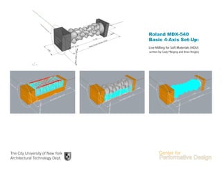
- 1. Live Milling for Soft Materials (HDU) written by Cody Pfleging and Brian Ringley The City University of New York Architectural Technology Dept. Roland MDX-540 Basic 4-Axis Set-Up:
- 2. 2 This material is based upon work supported by the National Science Foundation under Grant Numbers 1141234. Any opinions, findings, and conclusions or recommendations expressed in this material are those of the author(s) and do not necessarily reflect the views of the National Science Foundation.
- 3. 3 Fig. 1 - Machining Objects Menu Fig. 2 - RhinoCAM Menu Introduction RhinoCAM is a plug-in for Rhino used to create toolpaths for the CNC mill. It works from the modeling environment in Rhino to create simulations of the overall milling process before actually performing any milling. It then creates NC files (G-Code) which then can be read by the Roland MDX-540 for the milling process. Open RhinoCAM Operations Browser: (Fig. 2) - Toolbar Menu - RhinoCAM - Machining Operations Browser This is where you set up different machining operations and toolpaths. Open RhinoCAM Objects Browser: (Fig. 3) - Toolbar Menu - RhinoCAM - Machining Objects Browser This is where you load different tools for different machining jobs and regions/boundaries. Fig. 3 - Machining Operations Menu Roland- 4 Axis
- 4. 4 Roland- 4 AxisFig. 4 - Post Processor SetupFig. 5 - Machine Type Setup Fig. 6 - Machine and Post Processor Icons Step One: Machine Setup Set up the type of machine and the post processor that will be used for the milling process. In this guide, we will be using the Roland 4-Axis machine and the .nc output file. Machine Type: (Fig. 4) - Machining Operations Browser - Machine Set the Number of Axes to 4 Axis (Fig. 5). Post Processor: (Fig. 5) - Machining Operations Browser - Post Set the Current Post Processor to Roland MDX 540 by selecting it from the drop down menu (Fig. 6). If the post processor is not available, download the post processor from nycctfab.com/fabrication/ CNCmaching Make sure the Posted File Extension is set to .NC by selecting it from the drop down menu if it is not already set (Fig. 6).
- 5. Roland- 4 Axis 5 Fig. 7 - Stock Selection Step Two: Box Stock Setup Setting up your digital stock to match your physical material dimensions. Create a Box Stock: (Fig. 7) - Machining Operations Browser - Stock - Box Stock Set the location of the origin of the stock by clicking one of the corner buttons and set the dimensions of the Stock by typing in its Length, Width, and Height into the text boxes (Fig. 8). NOTE: This setting corresponds to the orientation of the milling process and must be the same origin at the mill. Fig. 8 - Stock Edit Fig. 9 - Stock in Model Space
- 6. Roland- 4 Axis 6 Fig. 10 - Selecting a Parallel Finishing Toolpath Step Three: 4-Axis Live Milling Roughingandfinishingyourgeometryusingtherotary axis. Create 2 Parallel Finishing Toolpaths - Machine Operation Browser - 4-Axis - Parallel Finishing NOTE: Rename toolpaths to indicate their purpose (e.g. “Parallel Roughing” or “Parallel Finishing”). Use a ball end mill for all live 4-Axis jobs.
- 7. Roland- 4 Axis 7 Fig. 11 - Axis: Step Down Control Fig. 12 - Axis: Cut Parameters Step Three (continued): 4-Axis Live Milling Important toolpathing considerations. Step Down Control: (Fig. 11) In the Step Down Control tab of the Parallel Roughing toolpath enter the dimension of your stock from its center to its outer most point. For a 4”x4”block of wood that value would be 2.835. NOTE: This can be left unchecked for your Parallel Finishing toolpath. Cut Parameters: (Fig. 12) In the Cut Parameters tab for both the Parallel Roughing and Parallel Finishing toolpaths, the Cut Axial Containment parameter should be offset by a minimum of the selected tool’s radius. NOTE: Run a simulation and check to see that the tool holder (collet nut) is not colliding with the portion of the stock used by the chuck or tailstock for securing the stock to the rotary.
- 8. Roland- 4 Axis 8 Fig. 13 - Simulate Tab Fig. 14 - Simulation Model Step Five: Simulate Toolpaths Confirm that toolpaths are safely producing the intended results. Run Simulations: (Fig. 14) - Select the toolpath to simulate - Machine Operation Browser - Simulate - Play Detect Collisions: (Fig. 15) Running a simulation of each of your toolpaths prior to posting is an essential part of the CNC milling process. It is very difficult for even an experienced RhinoCAM user to be confident that based on the data entered in your toolpathing parameters that you will produce the model you intend without first running the simulations. The most important reason to run the simulation of your toolpaths is to detect potential collisions. In this image the collet has collided with the stock. The areas where the collision has occurred are shown in red. This type of collision typically occurs when a endmill with a relatively small diameter is used (1/8”or less). These smaller endmills typically have shorter tool lengths, as well. As a result of this shorter tool length, the collet must move deeper into the stock in order for the endmill to reach its cutting surface. The collisions shown in the far left and right of this image are a prime examples of this type of collision. The endmill has removed material in order to get to a certain depth, but because the collet is wider it collides with the stock. By default, your original stock is displayed in orange and, as the simulation plays out, your geometry is displayed in gray. Collisions will show themselves in red.