"IADC Accredited Rig Inspection Workshop"
•
1 like•1,421 views

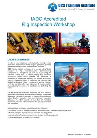
Planned maintenance and accurate inspections are essential to ensure the optimum performance for your rig, reduce downtime and maintain the safety of your personnel. OCS Training Institute is pleased to deliver and accredit a Drilling Rig Inspection Workshop which teaches the inspection and maintenance procedures required to ensure equipment integrity.

Recommended
More Related Content
What's hot
What's hot (20)
Viewers also liked
Viewers also liked (16)
Similar to "IADC Accredited Rig Inspection Workshop"
Similar to "IADC Accredited Rig Inspection Workshop" (20)
Recently uploaded
Recently uploaded (20)
"IADC Accredited Rig Inspection Workshop"
- 1. IADC Accredited Rig Inspection Workshop Course Description: In order to ensure optimum performance for your rig, reduce down time and maintain safety of your personnel, planned maintenance and accurate inspections are essential. OCS Training Institute is pleased to co-operate with a Global provider of Rig Inspection/Audits, Commissioning, Compliance & Acceptance as well as Engineering for Offshore Drilling Rigs, to deliver Drilling Rig Inspection Workshops (RIW) which teaches the inspection & maintenance procedures required to ensure equip-ment integrity. Candidates learn to implement the relevant stan- dards & understand industry requirements so that they can verify the condition of a rig’s equipment & improve safety, thus reducing the number of accidents and protecting the asset The Rig Inspection Workshop deals with the most common equip-ment deficiencies and recurring problems. It describes & explains the working principles of major drilling equipment using detailed examples from our technical inspection database. The RIW consists of four days of interactive classroom ses-sions with ample time for group participation and discussion. Additionally we provide the candidates with the following: • A checklist format for major equipment to assist with correct maintenance and inspections. • Multiple examples of good and bad practices, including photos. • A presentation of improvements and new designs of drilling equipment. • Further explanation of the workshop manual. All Rights Reserved. OCS GROUP
- 2. Course Objectives : After completing this workshop, candidates will be able to: Independently carry out a basic (visual) rig inspection. Describe the main inspection criteria for major equipment. Identify major items that have an impact on the safety and operation of a rig. Recognize the indicators of the overall condition of a drilling rig. List the relevant standards (such as API) and their implications for drilling equipment. Understand the basics of EX equipment installed in hazardous areas. Evaluate basic maintenance and inspection procedures on the rig to identify compliance with good work-ing practices and industry standards Who Should Attend : This course is specifically designed for, but not limited to employees in the oil and gas industry who holds the following roles: Drilling Engineers Rig Managers Toolpushers Drilling Managers Maintenance Supervisors Mechanics and Electricians HSE Consultants Drillers All Rights Reserved. OCS GROUP
- 3. All Rights Reserved. OCS GROUP RIG INSPECTIONS WORKSHOP DAY 1 - Drilling Equipment Course Agenda : 1.0 Drawworks Drawworks are powerful electrically-driven winches that lower and lift the drill string and casing. They also raise the derrick on land rigs using special raising lines. Some draw- works on older land rigs also drive the rotary table using a heavy duty chain drive. 1.1 Main characteristics 1.2 DC Drawworks checklist 1.3 AC Drawworks checklist 2.0 Rotary Table A rotating table rotates and supports the drill string when connections are to be made for the drill string or the casing. It is AC or DC electrically-driven or driven from the draw- works. Some rotary tables cannot be used to rotate the string; instead the top drive is used. Some rotary tables are hydraulically-driven to rotate with a low torque and low speed only. 2.1 Main characteristics 2.2 Rotary table checklist 3.0 Top Drive A top drive is a mechanical device on a drilling rig that provides clockwise torque to the drill string to facilitate the process of drilling a borehole. It is an alternative to rotary table. It is located at the swivel place and allows a vertical movement up and down the derrick. The advantage of a top drive over a rotary table is that it allows the rig to drill longer sections of drill pipe. A rotary table can only drill a single drill pipe at one time. 3.1 Main characteristics 3.2 Top drive checklist 4.0 Independent Swivel An independent swivel is a rotary tool that is installed in the hook at the bottom of the travelling block and allows the drill pipe to rotate while supporting the weight of the drill string. It also allows the passage of mud through the drill pipe at the same time. 4.1 Main characteristics 4.2 Independent swivel checklist 5.0 Crown and Travelling Block A crown block is a device situated at the top of an oil rig or derrick. It sits on the crown platform, which is a steel plat- form located along the upper portion of the rig. The crown block works in conjunction with a similar component, the traveling block, which is positioned just below the crown platform. Together, these two systems areknown as the block and tackle. Each crown block consists of a series of sheaves and steel cables. These cables and sheaves sit on a steel frame, which may be built into the structure of the derrick. The sheaves serve as drilling lines, and pass through the trav- eling block below to connect to the rig's hoisting drum. While the crown block itself is fixed and used to stabilize the sheaves, the traveling block moves up and down with the cables. 5.1 Crown block main characteristics 5.2 Travelling block main characteristics 5.3 Introduction to the crown block and travelling block 5.4 Crown block checklist 5.5 Travelling block checklist 6.0 The Derrick A derrick is a lifting device composed of a tower or a guyed mast, such as a pole, which is hinged freely at the bottom and which is sometimes controlled by four lines to keep the derrick straight. The derrick allows the rig to pull/lower three drill pipes (called a stand) at the same time. Some smaller land rigs pull two drill pipes (called doubles). 6.1 Main characteristics 6.2 Derrick checklist 7.0 Winches Winches are air or hydraulically driven lifting devices that lift heavy equipment and sometimes personnel (man-riding winch). 7.1 Main characteristics 7.2 Introduction air winches: man-riding winches 7.3 Man-riding winch 7.4 Winch checklist 8.0 Lifting and Handling Equipment API RP 8B gives guidelines and establishes requirements for inspection, maintenance, repair and remanufacture of items of hoisting equipment used in drilling and production operations, in order to maintain the serviceability of this equipment. 8.1 Main characteristics 8.2 Lifting and handling equipment checklist
- 4. All Rights Reserved. OCS GROUP RIG INSPECTIONS WORKSHOP DAY 2 - Part 1 Mud Processing Equipment 1.0 Mud Pump Mud pumps are large reciprocating piston/plunger devices that are specially designed to circulate drilling fluid (mud) under high pressure down the drill string and back up the annulus. 1.1 Main characteristics 1.2 Mud pump checklist 2.0 Mud System The mud system is a system of shakers, mud centrifuges, mud cleaners, mud desanders and mud desilters designed to circulate drilling fluid to the drill bit and back to the surface. A mud system has two sections. The high pressure section deliv- ers mud from the pumps to the drill bit. The low pressure section sends mud back to the surface for treatment and supplies mud from the mud pits back to the main pumps using a large number of centrifugal pumps. A vacuum degasser removes small particles of gas from the mud. 2.1 Main characteristics 2.2 Mud system checklist DAY 3 - Part 1 Electrical Equipment 1.0 Eddy Current Brake The eddy current brake is an extra brake for the drawworks. It is connected through a cou- pling with the drawworks main shaft and provides extra braking force to better control the drawworks. 1.1 Main characteristics 1.2 Baylor eddy current brake checklist 2.0 Electrical Safety Electrical equipment on drilling rigs have to comply with safety standards to protect the rigs from ignition of free flowing gas from the wells. The level of safety depends on the zone or area in which the electrical equipment operate. 2.1 Main characteristics 2.2 Electrical safety equipment checklist DAY 3 - Part 2 Safety Equipment 1.0 Drilling and Safety Equipment Drilling and safety equipment include fire pumps, fire extinguishing systems (both permanent and portable), PPE (personal protective equipment), hand rails, toe boards, escape routes, life-rafts and lifeboats for MODUs, helicopter decks. They protect personnel and provide equipment for fighting fires or abandoning the rig (MODUs). 1.1 Main characteristics 1.2 Safety equipment checklist 1.3 Drilling safety equipment checklist 2.0 Pollution Control The pollution control checklist includes equip- ment present at the rig site that prevent pollu- tion to the environment. Maintaining pollution control depends on location and local legisla- tion and the use of oil-based mud requires many extra pollution control measures. 2.1 Main characteristics 2.2 Pollution control checklist DAY 2 - Part 2 Engine Room And Power Plant 1.0 Diesel Engine The diesel engine is a high compression internal combustion engine that drives the main AC or DC generators, which provide power for the rig. 1.1 Main characteristics 1.2 Diesel engine checklist 1.3 Emergency generator checklist 2.0 Air Compressor Rig air compressors on the rig are used to supply compressed air to several auxiliary equipment and functions. Usually the systems build on drilling rigs are 120 psi systems fitted with several air receivers for the storage of compressed air. The air from the com- pressors is used for the operation of the rig floor winches, start air for the engines, operation of the air operated BOP hoist, supply air for the bulk transfer system, etc. 2.1 Main characteristics 2.2 Air compressor checklist (more relevant for MODUs) 3.0 Crane A crane is a machine for raising, lowering and revolving heavy equipment. They are used on land rigs and MODUs (marine cranes), and may be driven electronically, hydraulically or with a diesel engine. They can also lift heavy equipment between rigs and supply boats on MODUs and assist in building up land rigs on new locations. 3.1 Main characteristics 3.2 Crane checklist (relevant for MODUs)
- 5. RIG INSPECTIONS WORKSHOP DAY 3 - Part 3 Marine Equipment 1.0 Jacking System The jacking system lifts and lowers the entire rig in and out of the water on support legs. It comprises a large number of electrically-driven gears with gear boxes to control the legs (three or four) of the jack-up system. 1.1 Main characteristics 1.2 Pinion shaft, drive pinion and reduction gearbox 1.3 Jacking electric brake/motor and jacking control 1.4 Leg racks 1.5 Central control cabinet and console 1.6 Central control console 1.7 Brake operation 1.8 Fixation system 2.0 Associated Systems for Jacking Associated systems for jacking, including a seawater system, help ensure the leg footings will be maintained in a secure position for a number of factors including sea conditions, the weather window for jacking and a Site- Specific Assessment (SSA), for instance soil analy-sis. 2.1 Seawater system 2.2 Seawater system: Points to identify 2.3 Leg-jetting operation 2.4 Jack-up operation 2.5 Foundation failure while pre-driving 2.6 Jacking points to consider 2.7 Jacking system checklist 2.8 Practical explanation of the jacking system 2.9 Corrosion protection 3.0 Deep-well pumps Deep-well pumps supply cooling water so that the engines can be cooled even if the engines are working on maximum load for a prolonged period. It is important to find out how many pump strokes the mud pumps are allowed to make while pumping seawater, so that the deep-well pumps can keep up with the demand. 3.1 Jetting 3.2 Skidding 3.3 Spud can inspections 3.4 General jack-up marine equipment 4.0 Anchor Winches 4.1 Anchor winches checklist 4.2 Anchor winches: lessons learnt 5.0 Thrusters Thrusters are part of dynamic positioning / station keeping system for floating units which compensate wind, wave and current forces in a dynamic controlled mode to keep the unit on a predetermined location and heading at sea. 6.0 Navigation Equipment DAY 4 Well Control Equipment 1.0 Ram-Type Preventer A ram-type preventer is part of the well control equip- ment integrated into the BOP. It seals the annulus of the well, seals around the drill pipe or performs a Complete Shut Off (CSO) if no drill pipe is inside the hole. Rams can hang off the drill string and shear the drill pipe. 1.1 Main characteristics 1.2 Operation of the rams 1.3 Hydraulic operators 1.4 Types of rams 1.5 Ram preventer checklist 2.0 Annular Preventer An annular preventer seals the annulus of the well, seals around any pipe-casing or performs a CSO if no drill pipe is inside the hole. It is part of the well control equipment integrated into the BOP. The hydraulic clos-ing pressure drives a piston upwards, which forces the sealing element upwards and inwards to form a seal around the pipe in the hole. 2.1 Main characteristics 2.2 Principle of annular preventers 2.3 Stripping through a closed annular BOP 2.4 Hydril annular BOPs 2.5 Hydril GK annular preventers 2.6 Cameron annular BOPs 2.7 Annular preventer checklist 3.0 Gate Valve A gate valve is part of well control equipment integrated into the choke and kill lines of the BOPs. They seal off the choke and kill valve outlets. On each outlet there is normally one remotely-operated gate valve and one manually-operated gate valve. 3.1 Main characteristics 3.2 Gate valve checklist 4.0 Choke and Kill Manifold The choke and kill manifold is a collection of pipes and valves that restricts or stops pressure/flow and form part of the BOP system. Some land rigs have a simple choke manifold. Modern rigs and MODUs use a selection of gate valves integrat- ed into a choke and kill manifold. Both types are accom- panied by a mud/gas separator and vent lines. Upstream of the chokes, the manifold is connected to the BOPs. Downstream of the chokes, vent lines are routed to the mud/gas separator and the flare pit on land rigs or routed overboard on MODUs. 4.1 Main characteristics 4.2 Choke and kill manifold checklist All Rights Reserved. OCS GROUP
- 6. RIG INSPECTIONS WORKSHOP D 5.0 BOP HPU The BOP HPU (Hydraulic Power Unit) consists of three hydraulic circuits made by a set of accumulator bottles and hydraulic pumps. These are the accumulator circuit, the manifold circuit and the annular BOP circuit. Hydraulic power is stored in the accumulator bottles and this provides pump capacity to keep the accumulator system under pressure. The HPU provides control valves to select different functions of the BOP equipment. 5.1 Main characteristics 5.2 BOP HPU checklist 6.0 Subsea Control Systems Conventional subsea control systems use pod hoses to transfer the hydraulic supply and pilot signals to the subsea accumulators and pods. 6.1 Conventional BOP controls systems checklist 6.2 Conventional surface controls systems: lessons learnt 7.0 MUX Multiplex (MUX) systems use cables to transfer electrical and fibre-optic supply and pilot signals to the pods. Rigs conduit lines integrated into the marine risers and a hotline are used to transfer hydraulic power to the subsea accumulators. 7.1 MUX control systems checklist 8.0 Riser and Tensioner Equipment Marine risers are used to provide a return flow path between the wellbore and the drill vessel, and to guide the drill string or casing to the BOP stack on the ocean floor. 8.1 Riser and tensioner equipment checklist 8.2 Riser and tensioner equipment: lessons learnt All Rights Reserved. OCS GROUP