Laser lecture 09 (applications, fiber optics)
•
0 likes•970 views

Laser Physics- lecture notes

Recommended
More Related Content
What's hot
What's hot (20)
Viewers also liked
Similar to Laser lecture 09 (applications, fiber optics)
Similar to Laser lecture 09 (applications, fiber optics) (20)
More from Ibb University, Yemen + Jazan University, KSA
More from Ibb University, Yemen + Jazan University, KSA (7)
Recently uploaded
Recently uploaded (20)
Laser lecture 09 (applications, fiber optics)
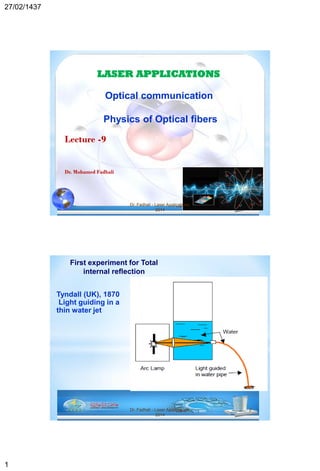
- 1. 27/02/1437 1 LASER APPLICATIONS Lecture -9 Dr. Mohamed Fadhali 1Dr. Fadhali - Laser Applications, 2014 Optical communication Physics of Optical fibers Dr. Fadhali - Laser Applications, 2014 2 Tyndall (UK), 1870 Light guiding in a thin water jet First experiment for Total internal reflection
- 2. 27/02/1437 2 Dr. Fadhali - Laser Applications, 2014 3 Dr. Fadhali - Laser Applications, 2014 4
- 3. 27/02/1437 3 Optical Communication System Optical Transmitter Comm. Channel Optical Receiver OutputElectrical Signal Input • Wavelength: 0.85, 1.3, 1.55 • SM & MM • DFB, VCSEL, FP, DBR • Modulation: Direct, external, integrated modulator Considerations: • SM & MM • Dispersion • Loss Optical fiber communication Dr. Fadhali - Laser Applications, 2014 6 Advantages of fiber optics
- 4. 27/02/1437 4 Core – Thin glass center of the fiber where light travels. Cladding – outer optical material surrounding the core Buffer Coating – plastic coating that protects the fiber. 7 Structure of fiber optics 8 1. According to the difference in refractive index profile Optical Fibers and Wave Propagation Dr. Fadhali - Laser Applications, 2014
- 5. 27/02/1437 5 9 2. According to number of propagated modes: 1) Single mode fiber(SMF) A single mode(fundamental mode) can propagate in the fiber. 2) Multi-mode fiber(MMF) Multi-modes can propagate in the fiber. Typical dimensions of different fibers Dr. Fadhali - Laser Applications, 2014 10 • Rays bend at interfaces between surfaces of different refractive indices – Snell’s law • Light remains confined in the core if the propagation angle is greater than the critical angle 2 1 21 1 sinsin n n 1 1 2 2sin sinn n 1 2 1 sinc n n 1 2 sin n n c 221 90sinsin nnn c Guiding light using fibers (rays analysis)
- 6. 27/02/1437 6 Dr. Fadhali - Laser Applications, 2014 Acceptance angle: (the max angle for coupling light into the fiber) Let’s consider the meridional rays α c n2 n2 α0 θc n1 n0 0 maximum coupling angle of the ray into the fiber c is the critical angle for total internal reflection. c is the critical propagation angle ccc nnnn cos2/sinsinsin 11100 n0 1 for air 2 2 2 22 0 0 1 1 1 1 2 1 sin cos 1 sin 1c c n n n n n n n n 11 From Snell’s Law Dr. Fadhali - Laser Applications, 2014 12 Numerical Aperture (NA) of the fiber NA = sine of the half of the maximum acceptance angle, typically, NA=0.15 for single mode fiber and 0.3 for MMF 2 2 2 1 2 1 2 1 2 1 2 1 1 2 n n NA n n n n n n n n 2 2 1/2 1/2 1 2 1 2 2 1 2 1 2 2 11 ( ) (2 ) where 2 NA n n n n n n n nn Assume that ∆ is the partial variation of refractive index
- 7. 27/02/1437 7 V-number (normalized frequency) ,)/996.01428.1( 2 Vb ,)( 2 2/12 2 2 1 nn a V ,41.2)( 2 2/12 2 2 1 nn a V c cutoff Number of modes when V>>2.41 , 2 2 V M Normalized propagation constant for V between 1.5 – 2.5. Mode field diameter (MFD) ), 1 1(22 V aw Dr. Fadhali - Laser Applications, 2014 13 Optical fiber parameters a: fiber radius Examples --- single mode and multi-mode fibers 1. Calculate the number of allowed modes in a multimode optical fiber of radius a = 100 m. The refractive indices of Its core and cladding are 1.468 and 1,447 respectively for the wavelength of 850 nm ,44.91)( 2 2/12 2 2 1 nn a V ,4181 2 2 V M Solution: a < 2.1m,4.2)( 2 2/12 2 2 1 nn a V Solution: Solution: Dr. Fadhali - Laser Applications, 2014 14 2. What should be the value of the fiber radius of a single mode fiber with refractive indices of core and cladding of 1.468 and1.447 respectively for the wavelength of 1.3m
- 8. 27/02/1437 8 Dr. Fadhali - Laser Applications, 2014 15 ,1.10)/11(22 0 mVaw 3. Calculate the mode field diameter of a single mode fiber with a core refractive index of 1.458 and cladding refractive index of 1.452 for the wavelength of 1.3m Dr. Fadhali - Laser Applications, 2014 16 HW1 A step index fiber of core radius and index 5um and 1.46 respectively. If the refractive index fractional difference is 0.01 , then find the numerical aperture and the maximum operating frequency for single mode propagation 1 2 2 2 1 1 1 1 0.01 0.99 0.99(1.46) 1.45 n n n n n n n 1 2 1.46 2(0.01) 0.206NA n max max 1 1 min 6 max8 14 max 22 2.405 2.405 2 2 2 (5 10 )(0.2064) 3 10 1.112 10 a V V n a n c Hz