SlideShare uma empresa Scribd logo
1 de 18
Baixar para ler offline
(12) United States Patent
Linna et al.
(54)
(75)
METHOD OF CONTROLLING
COMBUSTION IN A HOMOGENEOUS
CHARGE COMPRESSION IGNITION
ENGINE
Inventors: Jan-Roger Linna, Boston, MA (US);
Robert Bowyer, Cambridge (GB);
Bernard J. Challen, Sussex (GB);
John Paul Mello, Arlington, MA (US);
Peter Palmer, Carson City, NV (US);
Richard Stobart, Cambridge, MA (US)
(73) Assignee: Tiax LLC, Cambridge, MA (US)
( *) Notice: Subject to any disclaimer, the term of this
patent is extended or adjusted under 35
U.S.C. 154(b) by 269 days.
(21) Appl. No.: 10/223,573
(22) Filed:
(65)
Aug. 19, 2002
Prior Publication Data
(60)
(51)
(52)
(58)
(56)
US 2003/0145836 A1 Aug. 7, 2003
(Under 37 CFR 1.47)
Related U.S. Application Data
Provisional application No. 60/313,256, filed on Aug. 17,
2001.
Int. Cl? .................................................. F02M 7/00
U.S. Cl. ........................................ 123/435; 123/419
Field of Search ................................. 123/435, 436,
123/419, 295, 304, 294; 701!101
References Cited
U.S. PATENT DOCUMENTS
5,253,632 A
5,458,102 A
5,467,757 A
5,476,072 A
5,503,126 A
5,535,716 A
5,605,132 A *
10/1993
10/1995
11/1995
12/1995
4/1996
7/1996
2/1997
Brooks
Tomisawa et a!.
Yanagihara et a!.
Guy
Sakakibara et a!.
Sato eta!.
Hori et a!. ............. 123/406.24
111111 1111111111111111111111111111111111111111111111111111111111111
EP
EP
US006953024B2
(10) Patent No.:
(45) Date of Patent:
US 6,953,024 B2
Oct. 11, 2005
5,623,412 A
5,636,614 A
5,682,856 A
5,697,332 A
5,740,045 A
5,743,244 A
5,832,880 A
5,954,783 A
6,119,654 A
6,230,683 B1
6,286,482 B1 *
6,363,317 B1 *
6,698,394 B2 *
4/1997
6/1997
11/1997
12/1997
4/1998
4/1998
11/1998
9/1999
9/2000
5/2001
9/2001
3/2002
3/2004
Masson eta!.
Morikawa
Tomisawa et a!.
Asai eta!.
Livshiz et a!.
Bush eta!.
Dickey
Yamaguchi et a!.
Heiselbetz et a!.
zur Loye et a!.
Flynn et a!. ................ 123/435
Druzhinina et a!. ........ 701!104
Thomas ...................... 123/241
FOREIGN PATENT DOCUMENTS
0810363 A2 12/1997
1052383 A2 11/2000
(Continued)
OTHER PUBLICATIONS
Inagaki et al., "An adaptive fuel injection control with
internal model in automotive engines", (Nov. 27, 1990), vol.
1, Conf. 16, pp. 78-83, XP010038111.
(Continued)
Primary Examiner-Carl S. Miller
(74) Attorney, Agent, or Firm-Wolf, Greenfield & Sacks,
P.C.
(57) ABSTRACT
A method of controlling combustion in an homogenous
charge compression ignition engine through indirect mecha-
nisms. The method utilizes a predictive model so that
combustion can be controlled over a wide range of operating
conditions while maintaining optimum operation with
respect to efficiency and emissions. The methods include an
adaptive aspect, which allows the predictive model to be
updated if deemed necessary. Furthermore, the methods
include a model with a plurality of control modes. A control
mode can be chosen to optimize the engine for one of a
plurality of output characteristics, including response time,
efficiency, or emissions characteristics.
Fault Indication
23 Claims, 8 Drawing Sheets
Prediction
Error
US 6,953,024 B2
Page 2
JP
wo
wo
wo
wo
wo
wo
FOREIGN PATENT DOCUMENTS
11-2173
W098/10179
W099/40301
WO 99/42718 A1
W099/42718
WO 00/26526 A1
wo 01!44644 A2
1!1999
3/1998
8/1999
8/1999
8/1999
5!2000
12/2001
01HER PUBLICATIONS
Magnus Christensen and Bengt Johansson, Per ArnnJus and
Fabian Mauss, "Supercharged Homogeneous Charge Com-
pression Ignition" 1998 Society of Automotive Engineers,
Inc., Technical Papers pp. 980787 143-157.
Magnus Christensen and Bengt Johansson, "Homogeneous
Charge Compression Ignition with Water Injection", Society
of Automated Engineers Technical Paper 1999-01-0182,
Mar. 1-4, 1999.
Magnus Christensen and Bengt Johansson, "Influence of
Mixture Quality on Homogeneous Charge Compression
Ignition", Society of Automated Engineers Technical Paper
962454, Oct. 19-22, 1998.
Jurgen Willard, Rolf-Gunther Nieberding, Guide Vent and
Christian Enderle, "The Knocking Syndrome-its Cure and
its Potential" Society of Automated Engineers Technical
Paper 982483, Oct. 19-22, 1998.
Hisakazu Suzuki, Noriyuki Koike, and Matsuo Odaka,
"Combusion Control Method of Homogeneous Charge Die-
sel Engines" Society of Automotive Engineers, Technical
Paper 980509. 1998, pp. 89-95.
S. M. Aceves, J. R. Smith, C. K. Westbrook and W. J. Pitz,
"Compression Ratio Effect on Methane HCCI Combustion",
Journal of Engineering for Gas Turbines and Power, Jul.
1999, vol. 121, pp. 569-574.
* cited by examiner
U.S. Patent Oct. 11, 2005 Sheet 1 of 8
Input
L------r-------------
'
Fault Indication
Figure l
US 6,953,024 B2
Output
Prediction
Error
U.S. Patent
Fast
response
Oct. 11, 2005 Sheet 2 of 8
Low NOx
Maximum efficiency
.+
+
ICost functions
Figure 2
US 6,953,024 B2
:{> IActuators
U.S. Patent
Figure 3a
Oct. 11, 2005 Sheet 3 of 8
OctJ= o.4
D ctJ =o.45
m cil =o.s
mcil =o.55
• ctJ: 0.6
US 6,953,024 B2
Figure 3b
U.S. Patent Oct. 11, 2005 Sheet 4 of 8
11
10
9
~ 8
.Q
:;
0 7
>
"''; 6
"·a,
~ 5 ...
0
:;; 4
.a
E
~ 3
Maximum Number of Engine Revolutions tolerable for Changing Engine Load
at different Engine Speeds w/o being Perceived as Sluggish.
US 6,953,024 B2
o~~~~~~~~~~-Y~~~~~~~~~..~~~~~~~~~
500 1000 1500 2000 2500 3000 3500 4000 4500 5000 5500 6000
Engine Speed (RPM)
Figure 4
U.S. Patent Oct. 11, 2005 Sheet 5 of 8 US 6,953,024 B2
NOx Emissions vs Work ProdLJCed
1000 . . .....
100 ..
E0..
10
e
"'c
0
iii
"'EUJ
><
0
•z
0.1
0 4 8 8
IMEP-G (bar)
10 12 14
Thermal Efficiency vs Work Produced
45 ...••.
40
35
~
g30
·8
"'m I
~ 25
!._
20
15
10
0 2 4 8
IMEP-G (bar)
8 10 12 14
Figure 5
U.S. Patent Oct. 11, 2005 Sheet 6 of 8 US 6,953,024 B2
Combustion
Figure 6
U.S. Patent Oct. 11, 2005 Sheet 7 of 8 US 6,953,024 B2
Mapping
VGT rack
EGR
Fuel
socaclual
Figure 7
U.S. Patent Oct. 11, 2005 Sheet 8 of 8 US 6,953,024 B2
Figure 8
US 6,953,024 B2
1
METHOD OF CONTROLLING
COMBUSTION IN A HOMOGENEOUS
CHARGE COMPRESSION IGNITION
ENGINE
2
model, and identifying a desired time for combustion. It also
comprises measuring values of a plurality of engine oper-
ating parameters and providing the values to the model and
employing the model to define actuator control commands
CROSS REFERENCE TO RELATED
APPLICATIONS
This application claims the benefit of U.S. Provisional
Patent Application No. 60/313,256 filed Aug. 17, 2001
which is hereby incorporated by reference.
s associated with start of combustion occurring at the desired
time. Additionally it involves controlling the combustion in
the engine with the actuator control commands; measuring
an actual time for the start of combustion; and updating the
model based on a difference between the desired time and
10 the actual time for the start of combustion.
FIELD OF THE INVENTION
In another aspect of the invention, a method of controlling
combustion in a compression ignition distributed reaction
engine is disclosed. The method comprises providing a
model for controlling the start of combustion in a compres-This invention relates generally to a method of controlling
an internal combustion engine configured to burn a pre-
mixed charge of air and fuel, using auto-ignition to initiate
combustion. In particular the invention relates to a predic-
tive model based control system to control a process by
indirect mechanisms so that combustion can be controlled
15 sian ignition distributed reaction engine. The model com-
prising a plurality of control schemes for operating the
engine. The method includes supplying engine speed and/or
engine load requirements as inputs to the model; measuring
over a wide range of operating conditions while maintaining 20
optimum operation with respect to efficiency and emissions.
BACKGROUND OF THE INVENTION
In a Premixed Compression Ignition (PCI) engine or
Homogenous Charge Compression Ignition (HCCI) engine, 25
fuel is introduced into the cylinder prior to or early during
the compression stroke, i.e. prior to movement of the piston
towards top dead center (TDC). As the piston moves towards
TDC during the compression stroke, the air and fuel mixture
is compressed. As a consequence, the temperature and 30
pressure within the cylinder increases continuously during
the compression stroke. The increasing temperature results
in auto ignition of the air and fuel mixture at crank angles at
or near TDC. The result is combustion characterized by a
rapid cascade of detonations in different zones of the cyl- 35
inder as the piston is approaching TDC. This allows the
realization of an effective expansion ratio approaching the
geometric compression ratio (i.e, maximum efficiency) of
the engine. Additionally, if the air and fuel mixture is
sufficiently lean, the engine-out NOx and soot emissions will 40
be dramatically lower than those of typical Diesel and SI
engines.
values of a engine operating parameters; choosing at least
one of the plurality of control schemes after evaluating the
inputs and the engine speed and/or load requirements to
create a chosen control scheme; and controlling the start of
combustion in the engine with the chosen control scheme.
In yet another aspect of the invention, a method is
disclosed for controlling combustion in a CIDR engine to a
desired behavior. The method comprises sensing at least one
engine operating condition and predicting, based at least in
part on the at least one sensed engine operating condition, an
engine behavior. It further comprises setting at least one
actuator to a desired set point based, at least in part, on the
at least one of the predicted dynamic behavior and the
chemical kinetics to obtain the desired engine behavior.
Various embodiments of the present invention provide
certain advantages and overcome certain drawbacks of prior
control methods. Embodiments of the invention may not
share the same advantages, and those that do may not share
them under all circumstances. This being said, the present
invention provides numerous advantages including the
noted advantage of improved control of a combustion pro-
cess in a HCCI engine.
Further features and advantages of the present invention,
as well as the steps associated with various embodiments,
are described in detail below with reference to the accom-Most HCCI engines lack an actuating mechanism capable
of directly regulating the start of combustion and the rate of
heat release in combustion. Instead, combustion begins
when the air and fuel mixture has been compressed to
sufficiently high pressures and temperatures, and the pro-
gression of combustion is primarily determined by the
chemical kinetics of the combustion reaction
45 panying drawings.
BRIEF DESCRIPTION OF THE DRAWINGS
The foregoing and other objects, features and advantages
of the invention will be apparent from the following more
SUMMARY OF THE INVENTION
The methods of the present invention are adapted to
control combustion in a homogenous charge compression
ignition engine. Controlling combustion includes the use of
50 particular description of preferred embodiments of the
invention, as illustrated in the accompanying drawings in
which like reference characters refer to the same parts
throughout the different views. The drawings are not nec-
essarily to scale, emphasis instead being placed upon illus-
55 trating the principles of the invention.
a predictive model based control system to control the
combustion process by indirect mechanisms. The control
methods include adapting a model to reflect changes in the
operation of the HCCI engine. They include choosing
between multiple control modes to best meet the immediate 60
needs of the engine. A method may include one or more of
the aforementioned aspects, each independently or in
combination, contributing to improved control of combus-
tion in a HCCI engine.
In one aspect of the invention, a method is disclosed for 65
controlling combustion in an compression ignition distrib-
uted reaction engine. The method comprises providing a
FIG. 1 is a representation of predictive, look-ahead,
control algorithm for CIDR engines;
FIG. 2 is a schematic representation of the technique used
for calculating actuator settings, and where the control
system uses the most suitable cost function;
FIG. 3a is a schematic representation of a practical HCCI
cylinder charge composition with a mass average equiva-
lence ratio of 0.5;
FIG. 3b is a schematic representation of an idealized
HCCI cylinder charge composition with a mass average
equivalence ratio of 0.5;
US 6,953,024 B2
3
FIG. 4 is a chart showing an example of the maximum
number of engine revolutions acceptable for changing
engine load at different engine speeds in order to avoid
perception of sluggish or slow response;
4
2. Calculate new dynamic models for components and/or
processor of the engine to be controlled. This may include
the air and exhaust system, and the combustion process in
the cylinder. Both structure and parameters of the model are
5 adapted. The new results are stored.FIG. 5 are two graphs showing experimentally found NOx
emissions and thermal efficiency as functions of gross
indicated mean effective pressure (IMEP-G), and illustrating
that there are several combinations of the control parameters
used in the experiment (air/fuel ratio, intake charge tem-
perature and intake charge pressure) that provide stable and 10
robust engine operation, but sacrifice efficiency and/or NOx
emissions;
FIG. 6 is an example of a model structure to relate input
conditions to the effect on combustion;
FIG. 7 is a schematic diagram giving an example of the 15
control demands and intermediate signals used in a predic-
tive control algorithm; and
3. Decide which cost function to utilize, or adapt a cost
function to meet the particular objectives at the present time,
wherein a cost function is a mathematical relationship that
assist in optimization.
4. Use the cost function to optimize future control actions,
and if required apply constraints to actuator movement.
5. Use the calculated control signal to update the various
controlling actuators.
6. Check, using a classifier whether the new parameter
details fall into one of the fault classes initially taught to the
system.
FIG. 8 illustrates a feature space showing four fault
classes Cl to C4, with two features, f1 and f2.
DETAILED DESCRIPTION
A predictive, look-ahead, control algorithm for control-
ling combustion in HCCI engines according to an embodi-
20 ment of the present invention, is depicted schematically in
FIG. 2. The logic of this control algorithm is outlined as
follows:
The present invention provides optimum control of a
homogeneous charge compression ignition (HCCI) engine
(also referred to as a CIDR engine, as will be explained
below) with respect to efficiency and emissions. They
accomplish this through mechanisms that indirectly control 25
the start of combustion, and the rate of heat release in
combustion.
1) The input to the engine (i.e., driver throttle position in
automotive applications) is used to determine the new target
engine load required.
2) Using knowledge of the maximum time-delay accept-
able to avoid a sluggish response feeling for the specific
engine in the specific application (e.g. 100 ms), the number
of engine cycles available (n) to accomplish a significant
Although not shown, the engine is similar to a conven-
tional HCCI engine, except for the engine controller and
associated sensors and actuators for use with the present
invention. Accordingly, the engine includes a cylinder block
having a cylinder and a reciprocating piston disposed
therein. Various intake and exhaust valves communicate
with the cylinder to deliver charge to the cylinder and
exhaust by products as the engine may also include fuel and
air deliver systems, and other standard systems associated
with internal combustion engines.
30 change in engine load is determined.
3) Using a predictive model of the engine, which is stored
and updated at each control cycle and knowledge of the
current and future target operating condition identified as the
engine load, the different indirect load control parameters
35
available are screened and ranked based on (A) Response
Time, (B) Degree of Authority, (C) Effect on Combustion
Phasing, and (D) Engine Efficiency Penalties.
4) Based on the model-based screening in Step 3, anIn one embodiment, the methods comprise the use of a
predictive model used to determine appropriate controller
commands by predicting engine performance associated
with a plurality of controller command possibilities. Once
optimum controller commands have been identified, they are
implemented through actuators that are able to control
combustion through indirect means.
40
optimum combination of one or more indirect control
parameters giving sufficiently fast control with sufficient
authority, and with minimum cross-over effects on SOC and
efficiency penalties is identified.
5) Using the predictive model of the engine, a control
In yet another embodiment, the methods comprise the use
of a model of an HCCI engine to determine appropriate
controller commands. Once controller commands have been
identified and implemented, various resulting engine param-
eters are measured. The controller commands and the engine
parameters that resulted from the commands are then used to
update the HCCI engine model if deemed necessary.
45 strategy based on the optimum combination of control
parameters defined in Step 4 is determined. The control
strategy includes prediction of appropriate control parameter
settings cycle-by-cycle for the next n cycles such that the
engine load is regulated to the target load requested by the
50 driver, while SOC is maintained near TDC.
In still another embodiment, the methods comprise a
model that has a plurality of control modes. One or more
engine operating parameters are measured and then com- 55
pared to desired engine operating parameters. One of the
plurality of control modes is then chosen based on the
difference between the measured engine operating param-
eters and the desired engine operating parameters.
The following steps provide a broad overview of steps 60
that may be employed in an embodiment of the present
invention. They describe the process of calculating a new
control action, and using a predictive look-ahead algorithm
and are represented schematically in FIG. 1.
1. Compute the likely future load demand. This may 65
include estimating future load and/or speed demands for the
powertrain.
6) A sensor or sensors (to sense engine vibration or
crankshaft angular acceleration and other parameters, or
optical phenomena or a calculation where SOC is calculated
from ionization or pressure information) are used to sense
SOC and other engine operating characteristics such as
equivalence ratio in each engine cycle and provide a feed-
back signal to the predictive model for adaptive learning
7) As the engine condition changes, the predictive algo-
rithm uses a cost function appropriate to either a fast
response, a high efficiency operation, or a low NOx opera-
tion. During times of rapid change (as predicted by the load
estimation algorithm), the fast response cost function is
used. This cost function penalizes error (between actual and
demanded load) more than it does control effort. At small
error the cost function is adjusted to improve the engine
efficiency, by selecting one of the control variables as the
key variable to be controlled. For example at mid range load,
US 6,953,024 B2
5
the intake pressure may be used to control load, and it will
be the error in intake pressure that is penalized. Steps 1)
through 7) are repeated for every engine cycle.
6
before auto-ignition occurs. Also, when the engine is started,
the air in the intake manifold may be near atmospheric
pressure as a turbocharger or supercharger may not yet be
operational. This can mean that less air mass will beAs previously mentioned, in a HCCI engine, fuel is
introduced into the cylinder prior to or early during the
compression stroke. As the piston moves towards IDC, the
5 delivered to the cylinder, making it more difficult to realize
the temperatures required for the air and fuel mixture to
auto-ignite. Furthermore, the need to minimize harmful
pollutant emissions during such a start-up condition presents
an additional constraint on the development of cold start
air and fuel mixture is compressed and the temperature and
pressure within the cylinder increase until auto-ignition of
the air and fuel mixture occurs. The result is combustion
characterized by a rapid cascade of detonations in different 10
zones of the cylinder as the piston is approaching TDC.
Fuel can be introduced to the cylinder through techniques
similar to those found in many conventional spark ignition
engines. Perhaps the most reported method of introducing
1 15
fuel in HCCI engines is the use of traditional port fue
injection (PFI). An alternative method is the direct injection
(DI) of fuel during intake or early in the compression stroke.
These methods of introducing fuel can provide for a well
mixed air and fuel charge, however, they typically still have
h 20
significant spatial variations of the air/fuel ratio through t e
cylinder as shown in FIG. 3a. In particular, these variations
may exist with the piston is near TDC Accordingly, the
cylinder content of an HCCI engine is not likely to be
perfectly homogeneous as is represented in FIG. 3b.
Experimental studies have shown that the heat release rate
in practical HCCI configurations is controlled by chemical
kinetics, with mixing being a less significant factor. Chemi-
25
cal kinetics are the steps a reaction goes through in pro-
ceeding from reactants to products. Some of the factors that
30
affect chemical kinetics include the temperature at which the
reaction occurs, and the concentration of the reactants which
can include the mass average equivalence ratio, the amount
of exhaust gas recirculation, and the amount of injected
water to name few. Consequently, the combustion process in
35
HCCI engines can be considered a distributed reaction
process, as opposed to a flame propagation (as found in
many SI engines) or diffusion flame (as found in many other
compression ignition engines).
Following from these observations, the air and fuel mix- 40
ture in the cylinder of a HCCI engine can be described as a
plurality of regions, each defined by its own equivalence
ratio as shown in FIG. 3a. Each of the regions can be
considered a perfectly stirred reactor. The in-cylinder flow
field, including the flow-field generated by the fuel jet if 45
in-cylinder direct injection is used, and the resulting mixing
action can determine the size and the mixture strength
distribution of these perfectly stirred reactors. However, the
reaction rates within each reactor are controlled primarily by
chemical kinetics. Additionally, the overall combustion 50
reaction is primarily controlled by chemical kinetics. Given
these observations, a different label for HCCI engines, or
other engines operating in these modes may therefore be
Compression Ignition Distributed Reactions (CIDR).
Hereinafter, the term CIDR is used interchangeably with the 55
term HCCI to represent engines with a more or less homo-
geneous charge.
Although the advantages of CIDR engines have been
demonstrated in experimental programs at steady state oper-
ating points, the optimization of these engines over a prac- 60
tical range of operating conditions present additional chal-
lenges. Some of the technical issues to consider in practical
implementations of CIDR technology include:
Cold start: In CIDR engines, combustion is initiated when
the air and fuel charge reaches its auto-ignition temperature. 65
When the inlet air and components are cold, a greater
temperature change is required of the air and fuel charge
strategies.
Rate of heat release (ROHR): In conventional engines,
fluid mechanic sub-processes control the rate of combustion.
Such sub-processes include air-fuel mixing in diesel engines
or flame wrinkling, flame stretch, and mass and thermal
convection by turbulence in spark ignition engines. By
contrast, the ROHR is controlled through chemical kinetics
in CIDR engines, with ignition occurring spontaneously
throughout the cylinder. ROHR can be controlled in CIDR
engines by determining the intake charge temperature, fuel/
air ratio, and exhaust gas recirculation combinations that are
sufficient for the cylinder contents to ignite over the entire
engine operating map.
Power density: Many CIDR engines have lower power
densities because they frequently operate with lean mixtures
and large amounts of charge dilution to achieve appropriate
chemical kinetics. However, experiments have shown that
turbocharging or supercharging can dramatically increases
the attainable power density from CIDR from CIDR
engines. Consequently, there exists an optimization trade-off
between high boost pressure, which requires a lower com-
pression ratio due to limits on peak cylinder pressure, and
the thermal efficiency of the engine. To address this issue,
CIDR engines can adopt a mixed-mode operating concept
commonly employed for gasoline direct injection (GDI)
engines. In this approach, a first mode modes operates much
like a homogeneous stoichiometric spark ignition engine for
high loads with maximum air utilization; and a second mode
operates much like a lean homogeneous charge compression
ignition mode for low load and idle operation to achieve
maximum fuel economy and low NOx emissions.
Start of combustion (SOC) timing: From a control
standpoint, one of the most striking features of CIDR
engines is that there are generally no actuating mechanisms
available for directly regulating start of combustion, such as
spark timing in SI engines or injection timing in diesel
engines. Instead, start of combustion occurs when the fuel-
air mixture has been compressed to sufficiently high pres-
sures and temperatures, similar to auto-ignition or knock in
SI-engines. Most engine load control parameters, such as
charge energy density by temperature, pressure, or equiva-
lence ratio to name a few, tend to impact the in-cylinder
conditions. As a result, they may inadvertently affect when
combustion begins with respect to top dead center (also
known as combustion phasing) and thereby performance,
efficiency and emissions. Consequently, the achievement of
optimal SOC timing over a practical range of operating
conditions, engine speed in particular, is a complex task.
Also, coupling exists between SOC timing and many load
control variables, which are issues that need to be considered
in controlling the start of combustion.
Controlling combustion in CIDR engines, either the start
of combustion, or the rate of heat release, represents a
challenge to the commercialization of CIDR engines. If
auto-ignition occurs prematurely, or the rate of heat release
occurs too rapidly, it can cause undue stress on the mechani-
cal components and a lower thermal efficiency through a
lower effective expansion ratio. Likewise, if the conditions
US 6,953,024 B2
7
within the cylinder are not sufficient to promote auto-
ignition, partial or complete misfire can occur within the
cylinder resulting in very high hydrocarbon emissions and
loss of power.
An algorithm of the present invention is now described
with reference to FIG. 1 and FIG. 2. The algorithm begins
by defining a target engine load and/or speed, which is
typically provided directly by the operator of the engine. For
instance, in an automotive application, the position of the
gas pedal provides this input. This load and/or speed infor-
mation is translated into combustion requirements, such as
a desired start of combustion time, and/or a desired rate of
heart release by a set point generator, which are then passed
to the controller.
The set point generator may comprise a look up table in
some embodiments of the invention. In other embodiments,
the set point generator may even comprise models which
define the set point through mathematical relationships
instead of through lookup tables. Still, in other
embodiments, the controller may directly accept speed and/
or load demands and compute the combustion requirements
itself. Some embodiments of the invention may use a load
prediction algorithm to help in the optimization process. The
predictive control algorithm seeks to minimize future error,
and a knowledge of future demand is helpful in reaching an
optimal series of control actions. In such embodiments, the
load prediction algorithm is based on the assumption that
future control demand on the engine (speed and load) make
a smooth transition based on the inertia of the underlying
system.
Once a target engine load and/or speed are defined, the
algorithm chooses which of several control modes are used
to control the engine. FIG. 4 is a graph that generally
represents the maximum number of engine revolutions that
are generally acceptable for changing engine load at a given
engine speeds. If more time, or equivalently engine revolu-
tions are taken for changing engine load, the engine response
may be perceived as sluggish by the operator. For instance,
the in-cylinder condition must be changed in roughly 2
engine revolutions or one engine cycle for a four-stroke
engine when the engine is operating at a low engine speed
(1200 rpm). Some embodiments of the invention will place
8
plant (the engine) to the controller. Such parameters may
include, but are not limited to air mass flow, cam position,
crank position, engine coolant temperature, load demand,
intake air temperature, intake air pressure, engine speed,
5 engine load, exhaust gas temperature, exhaust gas recircu-
lation valve position, amount of exhaust gas recirculation,
equivalence ratio, exhaust air/fuel ratio, throttle position,
valve timing, turbocharger turbine speed, NOx emission
level, variable nozzle turbine setting, variable geometry
10
turbine setting, start of combustion, rate of heat release, and
wastegate position as the invention as the invention is not
limited in this respect.
Once a control mode is chosen and the engine operating
parameters are identified by the controller, it uses a predic-
15 tive model to evaluate the various actuator commands, or
equivalently, the plant input that it may use to control the
engine at the present engine operating parameter levels.
Such actuator control commands may include, but are not
limited to equivalence ratio, intake to exhaust heat-
20 exchanger bypass valve position, variable valve timing,
amount of exhaust gas recirculation, variable nozzle turbine
setting, variable geometry turbine setting, wastegate setting,
water injection timing, water injection amount, fuel injection
timing, fuel injection amount, exhaust restriction setting,
25 and electrically assisted turbocharger setting.
The model of the engine can represent a plurality of
engine subsystems models, such as its air inlet system,
turbocharger or supercharger system, fuel delivery system,
charge cooling system, exhaust system, and exhaust gas
30 recirculation system (EGR) to name a few. The model can
predict the dynamic behavior of the various subsystems for
various actuator control commands, and therefore can pre-
dict overall engine performance. Such dynamic behaviors of
these systems can include the motions of components, such
35 as predicted turbocharger speeds, predicted drivetrain
speeds, and other suitable device conditions as the invention
is not limited in this respect. Dynamic behaviors may also
refer to the predicted states or characteristics of various
engine processes, such as air or fluid transport times within
40 the engine subsystems, and heat and mass transfer behaviors
within the engine subsystems to name a few. Furthermore,
the chemical kinetics of the cylinder charge, such as ignition
delay and thermal formation of nitrogen oxides (NOx) maya priority on avoiding such a sluggish response. In these
embodiments, when a situation exists where the actual
engine load is significantly different than the desired engine 45
load, or equivalently the engine load error, the controller will
operate in a control mode that places a priority on a fast load
response. Once the load error is reduced to a predetermined
level, the controller may change to a different control mode,
such as one that places a priority on low NOx emissions, or
one that places a priority on maximum efficiency. FIG. 2 is
be predicted by the model.
The predictive model based control of the CIDR engine is
more complex than controlling an engine with a direct
actuating mechanism. The predictive, look-ahead model
based control has models of the engine and its sub-systems
that can accurately predict the dynamic behavior, such as
50 transport times and thermal inertia of all key components,
and the chemical kinetics of the cylinder charge, such as
ignition delay and thermal formation of nitrogen oxides
(NOx)·
a representative sketch of how each control mode may be
used by the controller. Each mode may be said to have its
own set of cost functions that are employed by the controller
to run the engine. These different cost functions are associ- 55
ated with placing a priority on particular engine performance
parameters of groups of such parameters. As mentioned
above, such parameters may include fast load response, low
NOx emissions, or maximum efficiency to name a few. FIG.
5 illustrates two examples showing that there are several 60
combinations of control parameters that provide stable
engine operations but sacrifice one of engine efficiency
and/or NOx emissions.
In addition to receiving combustion requirement informa-
tion from the set point generator, the controller may receive 65
input related to any engine operating parameters. This is
represented in FIG. 1 by the line connecting the output of the
The predictive algorithm uses its series of sub-models, in
some cases multivariable in character to form the basis for
the optimization process. For example, the intake charge
pressure and EGR are related through a multivariable frame-
work. A variable geometry turbocharger and an EGR valve
will be used to control both the EGR rate and the charge
pressure in the inlet manifold. A model of their behavior is
stored ready to be used for each control calculation. An
example of the format of this model is shown in FIG. 6. Two
models are maintained in parallel. An air system model is
used to relate VGT and EGR actuator positions and the
fuelling setting to the resulting air fuel ratio (AFR). A
combustion model is used to relate the charge parameters
(air fuel ratio, pressure and temperature) to the combustion
US 6,953,024 B2
9
phasing. Other models are used to represent other relation-
ships in the engine as represented in FIG. 7.
As previously mentioned, the control of combustion in an
HCCI engine is complex because HCCI engines generally
lack direct control mechanisms. Predictive model based
control of SOC is helpful in addressing this lack of a direct
control mechanisms. Knowledge of the steady state behavior
of the engine, and the dynamic behavior contained in the
model are used as a basis for calculating an optimal response
to the current engine conditions. Optimal response as used
here means the best response according to the chosen control
mode under the current engine operating parameters. In
evaluating actuator control commands, the controller applies
a plurality of simulated controller commands to the model
and predicts the engine output. This is accomplished by
using steady state settings for the actuators, and then adding
an optimal increment to each setting. The cost functions for
dynamic and static optimization are used by this aspect of
the algorithm to decide on control commands that relate to
the engine output that is being optimized. For instance, if
efficiency is being optimized the dynamic cost function will
include an estimate of efficiency-and so at each time step,
the control will seek to optimize efficiency.
In addition to the considerations above, there exists a
collection of indirect control parameters, and at any given
steady state operating condition it is possible to find several
combinations of these control parameters that will result in
acceptable SOC timings. However, these indirect control
parameters exhibit different key characteristics at different
engine operating conditions such as (1) degree of authority
or load control range, (2) response time, (3) effect on
combustion phasing SOC, (4) impact on engine-out
emissions, and (5) engine efficiency penalties. This is illus-
trated in FIG. 5 which shows thermal efficiency and NOx as
a function of engine load (or power) for different combina-
tions of intake charge temperature, pressure and equivalence
ratio. Clearly, not all control parameter combinations are
equally attractive from an emissions and efficiency stand-
point.
An ideal load control parameter or mechanism would
combine a large load control range with fast response time,
and little or no cross-over effect on combustion phasing,
engine-out emissions, and thermal efficiency.
10
complex objectives are reconciled by m1mm1zmg a cost
function. Depending on the particular performance
requirements, the nature of the cost function may be
changed. In this off-line optimization process, the relative
5 importance of the various controls at each load will be
identified. The relative importance will result in a mapping
function which will translate generic requirements into the
particular adjustments needed to effect the control change.
Once a set of actuator control commands are chosen, they
10 are used to control the various actuators that may indirectly
control combustion in a CIDR engine. The resulting engine
operating parameters are measured, and compared to the
values predicted by the model to define a prediction error.
These values may include any of the previously mentioned
15 engine operating parameters, and in particular, they may
include combustion characteristics, such as start of combus-
tion and rate of heat release. Such combustion characteristics
may be measured with accelerometer that detects vibrations
associated with the combustion process, although other
20 methods for sensing the combustion process may be used as
the invention is not limited in this respect. The prediction
error may be evaluated through any means known to those
in the art. One of such means includes a multi-mode
recursive least squares step which tracks the history of the
25 square of the error. Once the prediction error is evaluated, it
can be used to update the model in efforts to minimize future
prediction errors as represented in FIG. 1.
The model is able to use feedback signals for adaptive
learning to modify characteristic parameters such as the
30 auto-ignition characteristics of fuel so that variations or
disturbances can be accommodated. Such variations or dis-
turbances may include changes in fuel quality and compo-
sition between different fill-ups, or the gradual fouling of
heat exchangers within the engine to name a few, although
35 other factors may be included as the invention is not limited
in this respect. These variations and disturbances can be
accounted for by changing the model. Furthermore, a clas-
sification algorithm may be used in some embodiments of
the invention to decide whether the underlying cause of the
40 disturbance or variation should require the attention of the
engine operator. Such attention can include alerting the
operator to a change in the quality of the fuel, or alerting the
operator that heat the heat exchangers require maintenance
although other information could be provided to the operator
45 as the present invention is not limited in this respect.Consequently, at any operating condition, there often
exists one combination of control parameters that provides
optimum engine operation, including high efficiency, low
emissions, and good control authority. Thus, given a com-
mand to change operating condition, the controller must not
only find a combination of indirect control parameter set-
tings that ensures proper engine operation, it must also
determine what combination of parameters will change the
operating condition fast enough, and with the least adverse
effect on engine efficiency and emissions. Once the desired
operating condition has been reached, the controller can turn 55
to optimizing for optimum engine efficiency. The predictive,
model-based, look-ahead controller according to one
embodiment of the present invention is a multi-variable
predictive approach which will control several indirect con-
trol parameters to ensure sufficiently fast and accurate con-
trol of SOC with minimum adverse effect on engine effi-
ciency and emissions.
FIG. 8 shows an example of how the algorithm may
identify such variation and disturbances (faults) including
changes in delivered fuel quality. Two features that are
coupled to fuel quality, f1 and f2, may be used as indexes
50 into a feature space. The classification is indicated by the
area of the space. In practice there may be more than two
features used. When the indexes correspond to an area
associated with a particular fault, such as Cl, C2, C3, or C4,
a particular alert may be provided to the engine operator.
These predictive models offer several advantages over
other types of control algorithms such as feedback on error
only and feedforward with feedback. Unlike the feedback
approaches, the predictive approach can be fast with tailored
robustness and, therefore, useful for misfire avoidance. The
60 predictive approach can also be used in multi-variable form
with constraints, allowing for precise load control.
Furthermore, the predictive control approach can be used for
accurate SOC control since future load demand can be takenEmbodiments of the control system can also store the
steady state values of actuators to meet the engine's required
operating parameters including efficiency and emissions. 65
Those steady state parameters will be identified by running
a series of steady state conditions on a test bed. At each, the
into account. Because the predictive control is formulated as
an optimal control, the algorithm makes best use of the
actuation energy available. Another feature is illustrated in
FIG. 8 which shows a mapping process which takes the
US 6,953,024 B2
11
controller output signals and adapts them to the particular
needs of an engine. In this way the controller may be adapted
to a new design or different configuration.
While this invention has been particularly shown and
described with references to preferred embodiments thereof, 5
it will be understood by those skilled in the art that various
changes in form and details may be made therein without
departing from the scope of the invention encompassed by
the appended claims.
What is claimed is: 10
1. A method of controlling combustion in a compression
ignition distributed reaction engine to a desired behavior, the
method comprising:
sensing at least one engine operating condition;
15
predicting, based at least in part on the at least one sensed
engine operating condition, a dynamic engine behavior;
and
setting at least one actuator to a desired set point based,
at least in part, on the at least one of the predicted 20
dynamic behavior and the chemical kinetics to obtain
the desired engine behavior,
sensing a resulting engine behavior and further predicting,
based at least in part on the at least one sensed engine
operating condition and the resulting engine behavior, 25
at least one of the dynamic behavior of the at least one
engine component or process, and chemical kinetics of
an air/fuel charge; and
determining whether a short response time or engine
efficiency is a desired engine behavior to be achieved 30
and wherein setting the at least one actuator comprises
identifying at least one actuator that, when actuated,
will yield the determined desired engine behavior.
2. The method according to claim 1, wherein the dynamic
behavior is one of an air transport time and a charge 35
transport time.
3. The method according to claim 1, wherein the chemical
kinetics is NOx formation.
4. The method according to claim 1, wherein the chemical
kinetics is ignition delay. 40
5. The method according to claim 1, wherein sensing the
at least one engine operating condition comprises sensing an
engine load.
6. The method according to claim 1, wherein setting the
at least one actuator comprises setting the at least one 45
actuator to the desired set point within a time that is based
on a number of engine rotations.
7. The method according to claim 1, wherein setting the
at least one actuator comprises setting the at least one
actuator within 100 milliseconds of sensing the at least one 50
engine operating condition.
8. The method according to claim 1, wherein setting the
at least one actuator comprises identifying a plurality of
actuators to set and identifying a subset of the plurality of
actuators to set that will produce the desired engine behavior 55
within a desired response time.
9. The method according to claim 1 wherein setting the at
least one actuator comprises identifying a plurality of aetna-
tors to set and identifying a subset of the plurality of
actuators to set that will produce the desired engine behavior 60
with a least impact on engine efficiency.
10. The method according to claim 1, wherein sensing at
least one engine operating condition comprises sensing an
engine throttle position.
11. The method according to claim 1, wherein sensing a 65
resulting engine behavior comprises sensing engine vibra-
tion.
12
12. The method according to claim 1, wherein sensing a
resulting engine behavior comprises sensing a start of com-
bustion.
13. The method according to claim 1, wherein sensing a
resulting engine behavior comprises sensing an angular
acceleration of a crankshaft of the engine.
14. A method of controlling combustion in a compression
ignition distributed reaction engine, the method comprising:
providing an engine controller that includes:
a plurality of control modes, including: an engine
response control mode with an engine response time
minimizing cost function and an engine efficiency
control mode with an efficiency maximizing cost
function;
a model of engine operation, the model adapted to
receive a plurality of sets of simulated actuator
control parameters and engine operating parameters
and to provide predicted engine output for each set of
simulated actuator control parameters;
operating the engine in the engine efficiency control
mode;
providing a desired engine response requirement and
engine operating parameters to the controller;
changing from the engine efficiency control mode to the
engine response control mode when the engine effi-
ciency control mode cannot meet the desired engine
response requirement;
evaluating a plurality of sets of actuator control param-
eters by applying a corresponding plurality of sets
simulated control parameters and the engine operating
parameters to the model, which in turn employs the
response time minimizing cost function to provide
corresponding sets of predicted engine output;
comparing the plurality the sets of predicted engine output
with the desired engine response requirement; and
controlling the engine by implementing a set of the
plurality of actuator control parameters that best satis-
fies the engine response time minimizing cost function.
15. The method of claim 14, wherein the desired engine
response requirement is an engine speed.
16. The method of claim 14, wherein the desired engine
response requirement is an engine load.
17. The method of claim 14, further comprising:
measuring actual engine output and updating the model
based on a difference between the predicted engine
output and the actual engine output.
18. The method of claim 17, wherein the actual engine
output includes an actual start of combustion time and the
predicted engine output includes a predicted start of com-
bustion time.
19. The method of claim 14, wherein controlling com-
prises controlling the engine with the one of the plurality of
actuator control parameters such that the desired engine
response requirement is met within 100 milliseconds of
implementing the one of the plurality of actuator control
parameters.
20. The method of claim 14, wherein the plurality of
engine operating parameters are chosen from the group
consisting of: air mass flow signal, cam signal, crank angle
signal, engine coolant temperature, load demand, intake air
temperature, intake air pressure, engine speed, engine load,
exhaust gas temperature, exhaust gas recirculation valve
position, amount of exhaust gas recirculation, equivalence
ratio, exhaust air/fuel ratio, throttle position, valve timing,
turbocharger turbine speed, NOx emission level, variable
US 6,953,024 B2
13
nozzle turbine setting, variable geometry turbine setting, and
wastegate position.
21. The method of claim 14, wherein the actuator control
parameters are selected from a group consisting of: equiva-
lence ratio, intake to exhaust heat-exchanger bypass valve s
position, variable valve timing, amount of exhaust gas
recirculation, variable nozzle turbine setting, variable geom-
etry turbine setting, wastegate setting, water injection, fuel
injection timing, fuel injection amount, exhaust restriction,
and electrically assisted turbocharger setting.
14
22. The method of claim 14, wherein the controller further
comprises at least one additional control mode selected from
the group consisting of: a control mode to optimize load
control range, a control mode to optimize effects on com-
bustion phasing of start of combustion, and a control mode
to optimize engine emissions.
23. The method of claim 14, wherein the engine efficiency
control mode is an engine fuel consumption control mode.
* * * * *
UNITED STATES PATENT AND TRADEMARK OFFICE
CERTIFICATE OF CORRECTION
PATENT NO. : 6,953,024 B2 Page 1 of 1
APPLICATIONNO. : 10/223573
DATED : October 11, 2005
INVENTOR(S) : Jan-Roger Linna et al.
It is certified that error appears in the above-identified patent and that said Letters Patent is
hereby corrected as shown below:
On the title page, item [75],
INVENTOR(S):
Jan-Roger Linna, Boston, MA (US);
Robert Bowyer, Cambridge, (GB);
Bernard J. Challen, Sussex (GB);
John Paul Mello, Arlington, MA (US);
Peter Palmer, Carson City, NV (US);
Richard Stobart, Cambridge, MA (US)
should read,
INVENTOR(S):
Jan-Roger Linna, Boston, MA (US);
Bernard J. Challen, Sussex (GB);
John Paul Mello, Arlington, MA (US);
Peter Palmer, Carson City, NV (US);
Richard Stobart, Cambridge (GB)
Signed and Sealed this
Twenty-ninth Day ofApril, 2008
JONW.DUDAS
Director ofthe United States Patent and Trademark Office

Mais conteúdo relacionado

Destaque

A Novel Approach for Cancer Detection in MRI Mammogram Using Decision Tree In...
A Novel Approach for Cancer Detection in MRI Mammogram Using Decision Tree In...A Novel Approach for Cancer Detection in MRI Mammogram Using Decision Tree In...
A Novel Approach for Cancer Detection in MRI Mammogram Using Decision Tree In...CSCJournals
 
PHP 7 - Above and Beyond
PHP 7 - Above and BeyondPHP 7 - Above and Beyond
PHP 7 - Above and Beyondrafaelfqf
 
Publizitate agentzia berria egitear dago
Publizitate agentzia berria egitear dagoPublizitate agentzia berria egitear dago
Publizitate agentzia berria egitear dagoAsier Lemuria
 
Piddington CPD - Mediation - 9 November 2016 Final
Piddington CPD - Mediation - 9 November 2016 FinalPiddington CPD - Mediation - 9 November 2016 Final
Piddington CPD - Mediation - 9 November 2016 FinalAaron McDonald
 
Cocktails alcohol(5)
Cocktails alcohol(5)Cocktails alcohol(5)
Cocktails alcohol(5)audicastell
 
Orbitz and Spring Webflow Case Study
Orbitz and Spring Webflow Case StudyOrbitz and Spring Webflow Case Study
Orbitz and Spring Webflow Case StudyMark Meeker
 
Joomla! Testing - J!DD Germany 2016
Joomla! Testing - J!DD Germany 2016Joomla! Testing - J!DD Germany 2016
Joomla! Testing - J!DD Germany 2016Yves Hoppe
 
WordPressとS3で落ちないコーポレートサイトを立ち上げよう
WordPressとS3で落ちないコーポレートサイトを立ち上げようWordPressとS3で落ちないコーポレートサイトを立ち上げよう
WordPressとS3で落ちないコーポレートサイトを立ち上げようIchiro Tsuji
 
AWSでWordPressを使って富を得た時の話 (JAWS FESTA 東海道 2016 セッション)
AWSでWordPressを使って富を得た時の話 (JAWS FESTA 東海道 2016 セッション)AWSでWordPressを使って富を得た時の話 (JAWS FESTA 東海道 2016 セッション)
AWSでWordPressを使って富を得た時の話 (JAWS FESTA 東海道 2016 セッション)Kiminori Yokoi
 
[JAWS-UG関西IoT専門支部] IoTで関西のコミュニティをつなぐ
[JAWS-UG関西IoT専門支部] IoTで関西のコミュニティをつなぐ [JAWS-UG関西IoT専門支部] IoTで関西のコミュニティをつなぐ
[JAWS-UG関西IoT専門支部] IoTで関西のコミュニティをつなぐ Ichiro Tsuji
 
Siggraph2016 - The Devil is in the Details: idTech 666
Siggraph2016 - The Devil is in the Details: idTech 666Siggraph2016 - The Devil is in the Details: idTech 666
Siggraph2016 - The Devil is in the Details: idTech 666Tiago Sousa
 
Making JavaScript Accessible
Making JavaScript AccessibleMaking JavaScript Accessible
Making JavaScript AccessibleDennis Lembree
 
ポスト・フラットデザイン 〜フラットデザイン2.0とCSSフレームワーク〜
ポスト・フラットデザイン 〜フラットデザイン2.0とCSSフレームワーク〜ポスト・フラットデザイン 〜フラットデザイン2.0とCSSフレームワーク〜
ポスト・フラットデザイン 〜フラットデザイン2.0とCSSフレームワーク〜Akihiko Horiuchi
 
The Rendering Technology of Killzone 2
The Rendering Technology of Killzone 2The Rendering Technology of Killzone 2
The Rendering Technology of Killzone 2Guerrilla
 
3. types of entrepreneurs and their characteristics
3. types of entrepreneurs and their characteristics3. types of entrepreneurs and their characteristics
3. types of entrepreneurs and their characteristicsabcde123321
 

Destaque (20)

A Novel Approach for Cancer Detection in MRI Mammogram Using Decision Tree In...
A Novel Approach for Cancer Detection in MRI Mammogram Using Decision Tree In...A Novel Approach for Cancer Detection in MRI Mammogram Using Decision Tree In...
A Novel Approach for Cancer Detection in MRI Mammogram Using Decision Tree In...
 
PHP 7 - Above and Beyond
PHP 7 - Above and BeyondPHP 7 - Above and Beyond
PHP 7 - Above and Beyond
 
IJCSI-2015-12-2-10138 (1) (2)
IJCSI-2015-12-2-10138 (1) (2)IJCSI-2015-12-2-10138 (1) (2)
IJCSI-2015-12-2-10138 (1) (2)
 
Pas 115 presentation
Pas 115 presentationPas 115 presentation
Pas 115 presentation
 
Publizitate agentzia berria egitear dago
Publizitate agentzia berria egitear dagoPublizitate agentzia berria egitear dago
Publizitate agentzia berria egitear dago
 
Piddington CPD - Mediation - 9 November 2016 Final
Piddington CPD - Mediation - 9 November 2016 FinalPiddington CPD - Mediation - 9 November 2016 Final
Piddington CPD - Mediation - 9 November 2016 Final
 
Cocktails alcohol(5)
Cocktails alcohol(5)Cocktails alcohol(5)
Cocktails alcohol(5)
 
Digital strategy ottawa
Digital strategy  ottawaDigital strategy  ottawa
Digital strategy ottawa
 
Orbitz and Spring Webflow Case Study
Orbitz and Spring Webflow Case StudyOrbitz and Spring Webflow Case Study
Orbitz and Spring Webflow Case Study
 
Joomla! Testing - J!DD Germany 2016
Joomla! Testing - J!DD Germany 2016Joomla! Testing - J!DD Germany 2016
Joomla! Testing - J!DD Germany 2016
 
WordPressとS3で落ちないコーポレートサイトを立ち上げよう
WordPressとS3で落ちないコーポレートサイトを立ち上げようWordPressとS3で落ちないコーポレートサイトを立ち上げよう
WordPressとS3で落ちないコーポレートサイトを立ち上げよう
 
AWSでWordPressを使って富を得た時の話 (JAWS FESTA 東海道 2016 セッション)
AWSでWordPressを使って富を得た時の話 (JAWS FESTA 東海道 2016 セッション)AWSでWordPressを使って富を得た時の話 (JAWS FESTA 東海道 2016 セッション)
AWSでWordPressを使って富を得た時の話 (JAWS FESTA 東海道 2016 セッション)
 
View Monitoring Tips
View Monitoring TipsView Monitoring Tips
View Monitoring Tips
 
[JAWS-UG関西IoT専門支部] IoTで関西のコミュニティをつなぐ
[JAWS-UG関西IoT専門支部] IoTで関西のコミュニティをつなぐ [JAWS-UG関西IoT専門支部] IoTで関西のコミュニティをつなぐ
[JAWS-UG関西IoT専門支部] IoTで関西のコミュニティをつなぐ
 
Learning organization
Learning organizationLearning organization
Learning organization
 
Siggraph2016 - The Devil is in the Details: idTech 666
Siggraph2016 - The Devil is in the Details: idTech 666Siggraph2016 - The Devil is in the Details: idTech 666
Siggraph2016 - The Devil is in the Details: idTech 666
 
Making JavaScript Accessible
Making JavaScript AccessibleMaking JavaScript Accessible
Making JavaScript Accessible
 
ポスト・フラットデザイン 〜フラットデザイン2.0とCSSフレームワーク〜
ポスト・フラットデザイン 〜フラットデザイン2.0とCSSフレームワーク〜ポスト・フラットデザイン 〜フラットデザイン2.0とCSSフレームワーク〜
ポスト・フラットデザイン 〜フラットデザイン2.0とCSSフレームワーク〜
 
The Rendering Technology of Killzone 2
The Rendering Technology of Killzone 2The Rendering Technology of Killzone 2
The Rendering Technology of Killzone 2
 
3. types of entrepreneurs and their characteristics
3. types of entrepreneurs and their characteristics3. types of entrepreneurs and their characteristics
3. types of entrepreneurs and their characteristics
 

Semelhante a 86 jan-roger linna - 6953024 - method of controlling combustion in a homogeneous charge compression ignition engine

80 jan-roger linna - 6845760 - internal combusion engine transient fuel con...
80   jan-roger linna - 6845760 - internal combusion engine transient fuel con...80   jan-roger linna - 6845760 - internal combusion engine transient fuel con...
80 jan-roger linna - 6845760 - internal combusion engine transient fuel con...Mello_Patent_Registry
 
Variable Speed Drives for Gas compressor Operations
Variable Speed Drives for Gas compressor OperationsVariable Speed Drives for Gas compressor Operations
Variable Speed Drives for Gas compressor OperationsVijay Sarathy
 
COMPUTATIONAL FLUID DYNAMIC ANALYSIS OF A PULSE JET ENGINE
COMPUTATIONAL FLUID DYNAMIC ANALYSIS OF A PULSE JET ENGINECOMPUTATIONAL FLUID DYNAMIC ANALYSIS OF A PULSE JET ENGINE
COMPUTATIONAL FLUID DYNAMIC ANALYSIS OF A PULSE JET ENGINEIRJET Journal
 
95 john paul mello - 7237539 - control method and apparatus for use in an a...
95   john paul mello - 7237539 - control method and apparatus for use in an a...95   john paul mello - 7237539 - control method and apparatus for use in an a...
95 john paul mello - 7237539 - control method and apparatus for use in an a...Mello_Patent_Registry
 
Intake plenum Volume
Intake plenum VolumeIntake plenum Volume
Intake plenum VolumeAshok Kumar
 
Engine plant model_development for hil system and application to on-board dia...
Engine plant model_development for hil system and application to on-board dia...Engine plant model_development for hil system and application to on-board dia...
Engine plant model_development for hil system and application to on-board dia...Yixin Chen
 
HCCI-VCR Rotary Engine White Paper
HCCI-VCR Rotary Engine White PaperHCCI-VCR Rotary Engine White Paper
HCCI-VCR Rotary Engine White PaperCustomachinery Inc.
 
135 paulo mello - 8491278 - auxiliary braking device for wellhead having pr...
135   paulo mello - 8491278 - auxiliary braking device for wellhead having pr...135   paulo mello - 8491278 - auxiliary braking device for wellhead having pr...
135 paulo mello - 8491278 - auxiliary braking device for wellhead having pr...Mello_Patent_Registry
 
76 roberto o. pellizzari - 6820598 - capillary fuel injector with metering ...
76   roberto o. pellizzari - 6820598 - capillary fuel injector with metering ...76   roberto o. pellizzari - 6820598 - capillary fuel injector with metering ...
76 roberto o. pellizzari - 6820598 - capillary fuel injector with metering ...Mello_Patent_Registry
 
Doubling a VFD driven test-stand’s throughput and capacity
Doubling a VFD driven test-stand’s throughput and capacityDoubling a VFD driven test-stand’s throughput and capacity
Doubling a VFD driven test-stand’s throughput and capacityVacon Plc
 
4736 4740.output
4736 4740.output4736 4740.output
4736 4740.outputj1075017
 
IRJET- A Review of Testing of Multi Cylinder S.I. Petrol Engine
IRJET-  	  A Review of Testing of Multi Cylinder S.I. Petrol EngineIRJET-  	  A Review of Testing of Multi Cylinder S.I. Petrol Engine
IRJET- A Review of Testing of Multi Cylinder S.I. Petrol EngineIRJET Journal
 
ISABE-2003-1110
ISABE-2003-1110ISABE-2003-1110
ISABE-2003-1110rezaeiho
 
1 s2.0-s0016236111006958-main
1 s2.0-s0016236111006958-main1 s2.0-s0016236111006958-main
1 s2.0-s0016236111006958-mainesteban3pp
 
Variable compression ratio
Variable compression ratioVariable compression ratio
Variable compression ratioprj_publication
 
Effect of Modified Design on Engine Fuel Efficiency
Effect of Modified Design on Engine Fuel Efficiency Effect of Modified Design on Engine Fuel Efficiency
Effect of Modified Design on Engine Fuel Efficiency IJERA Editor
 

Semelhante a 86 jan-roger linna - 6953024 - method of controlling combustion in a homogeneous charge compression ignition engine (20)

80 jan-roger linna - 6845760 - internal combusion engine transient fuel con...
80   jan-roger linna - 6845760 - internal combusion engine transient fuel con...80   jan-roger linna - 6845760 - internal combusion engine transient fuel con...
80 jan-roger linna - 6845760 - internal combusion engine transient fuel con...
 
Us20180230913 a1
Us20180230913 a1Us20180230913 a1
Us20180230913 a1
 
Seminar Report on free piston engine
Seminar Report on free piston engineSeminar Report on free piston engine
Seminar Report on free piston engine
 
Variable Speed Drives for Gas compressor Operations
Variable Speed Drives for Gas compressor OperationsVariable Speed Drives for Gas compressor Operations
Variable Speed Drives for Gas compressor Operations
 
COMPUTATIONAL FLUID DYNAMIC ANALYSIS OF A PULSE JET ENGINE
COMPUTATIONAL FLUID DYNAMIC ANALYSIS OF A PULSE JET ENGINECOMPUTATIONAL FLUID DYNAMIC ANALYSIS OF A PULSE JET ENGINE
COMPUTATIONAL FLUID DYNAMIC ANALYSIS OF A PULSE JET ENGINE
 
95 john paul mello - 7237539 - control method and apparatus for use in an a...
95   john paul mello - 7237539 - control method and apparatus for use in an a...95   john paul mello - 7237539 - control method and apparatus for use in an a...
95 john paul mello - 7237539 - control method and apparatus for use in an a...
 
N130305105111
N130305105111N130305105111
N130305105111
 
Intake plenum Volume
Intake plenum VolumeIntake plenum Volume
Intake plenum Volume
 
Engine plant model_development for hil system and application to on-board dia...
Engine plant model_development for hil system and application to on-board dia...Engine plant model_development for hil system and application to on-board dia...
Engine plant model_development for hil system and application to on-board dia...
 
HCCI-VCR Rotary Engine White Paper
HCCI-VCR Rotary Engine White PaperHCCI-VCR Rotary Engine White Paper
HCCI-VCR Rotary Engine White Paper
 
135 paulo mello - 8491278 - auxiliary braking device for wellhead having pr...
135   paulo mello - 8491278 - auxiliary braking device for wellhead having pr...135   paulo mello - 8491278 - auxiliary braking device for wellhead having pr...
135 paulo mello - 8491278 - auxiliary braking device for wellhead having pr...
 
76 roberto o. pellizzari - 6820598 - capillary fuel injector with metering ...
76   roberto o. pellizzari - 6820598 - capillary fuel injector with metering ...76   roberto o. pellizzari - 6820598 - capillary fuel injector with metering ...
76 roberto o. pellizzari - 6820598 - capillary fuel injector with metering ...
 
Doubling a VFD driven test-stand’s throughput and capacity
Doubling a VFD driven test-stand’s throughput and capacityDoubling a VFD driven test-stand’s throughput and capacity
Doubling a VFD driven test-stand’s throughput and capacity
 
4736 4740.output
4736 4740.output4736 4740.output
4736 4740.output
 
Kn3419111915
Kn3419111915Kn3419111915
Kn3419111915
 
IRJET- A Review of Testing of Multi Cylinder S.I. Petrol Engine
IRJET-  	  A Review of Testing of Multi Cylinder S.I. Petrol EngineIRJET-  	  A Review of Testing of Multi Cylinder S.I. Petrol Engine
IRJET- A Review of Testing of Multi Cylinder S.I. Petrol Engine
 
ISABE-2003-1110
ISABE-2003-1110ISABE-2003-1110
ISABE-2003-1110
 
1 s2.0-s0016236111006958-main
1 s2.0-s0016236111006958-main1 s2.0-s0016236111006958-main
1 s2.0-s0016236111006958-main
 
Variable compression ratio
Variable compression ratioVariable compression ratio
Variable compression ratio
 
Effect of Modified Design on Engine Fuel Efficiency
Effect of Modified Design on Engine Fuel Efficiency Effect of Modified Design on Engine Fuel Efficiency
Effect of Modified Design on Engine Fuel Efficiency
 

Mais de Mello_Patent_Registry

134 mark s. thompson - 8449349 - elevator load bearing member having a jack...
134   mark s. thompson - 8449349 - elevator load bearing member having a jack...134   mark s. thompson - 8449349 - elevator load bearing member having a jack...
134 mark s. thompson - 8449349 - elevator load bearing member having a jack...Mello_Patent_Registry
 
133 stephanie mello - 8439759 - system and method of facilitating external ...
133   stephanie mello - 8439759 - system and method of facilitating external ...133   stephanie mello - 8439759 - system and method of facilitating external ...
133 stephanie mello - 8439759 - system and method of facilitating external ...Mello_Patent_Registry
 
132 qian wang - 8415131 - m13 bacteriophage as a chemoaddressable nanoparti...
132   qian wang - 8415131 - m13 bacteriophage as a chemoaddressable nanoparti...132   qian wang - 8415131 - m13 bacteriophage as a chemoaddressable nanoparti...
132 qian wang - 8415131 - m13 bacteriophage as a chemoaddressable nanoparti...Mello_Patent_Registry
 
130 michael m. iwatake - 8288828 - via contact structure having dual silici...
130   michael m. iwatake - 8288828 - via contact structure having dual silici...130   michael m. iwatake - 8288828 - via contact structure having dual silici...
130 michael m. iwatake - 8288828 - via contact structure having dual silici...Mello_Patent_Registry
 
129 andrew z. fire - 8283329 - genetic inhibition of double-stranded rna
129   andrew z. fire - 8283329 - genetic inhibition of double-stranded rna129   andrew z. fire - 8283329 - genetic inhibition of double-stranded rna
129 andrew z. fire - 8283329 - genetic inhibition of double-stranded rnaMello_Patent_Registry
 
128 phillip d. zamore - 8232260 - in vivo production of small interfering r...
128   phillip d. zamore - 8232260 - in vivo production of small interfering r...128   phillip d. zamore - 8232260 - in vivo production of small interfering r...
128 phillip d. zamore - 8232260 - in vivo production of small interfering r...Mello_Patent_Registry
 
127 dennis cherok - 8182545 - implantable prosthesis
127   dennis cherok - 8182545 - implantable prosthesis127   dennis cherok - 8182545 - implantable prosthesis
127 dennis cherok - 8182545 - implantable prosthesisMello_Patent_Registry
 
126 daniel j. nelson - 8180712 - methods and apparatus for determining whet...
126   daniel j. nelson - 8180712 - methods and apparatus for determining whet...126   daniel j. nelson - 8180712 - methods and apparatus for determining whet...
126 daniel j. nelson - 8180712 - methods and apparatus for determining whet...Mello_Patent_Registry
 
125 robert f. bigelow, jr. - 8100754 - gaming system having multi-player wh...
125   robert f. bigelow, jr. - 8100754 - gaming system having multi-player wh...125   robert f. bigelow, jr. - 8100754 - gaming system having multi-player wh...
125 robert f. bigelow, jr. - 8100754 - gaming system having multi-player wh...Mello_Patent_Registry
 
124 michael mello - 7990543 - surface characterization based on optical pha...
124   michael mello - 7990543 - surface characterization based on optical pha...124   michael mello - 7990543 - surface characterization based on optical pha...
124 michael mello - 7990543 - surface characterization based on optical pha...Mello_Patent_Registry
 
123 goldino alves - 7971687 - elevator belt assembly with noise reducing gr...
123   goldino alves - 7971687 - elevator belt assembly with noise reducing gr...123   goldino alves - 7971687 - elevator belt assembly with noise reducing gr...
123 goldino alves - 7971687 - elevator belt assembly with noise reducing gr...Mello_Patent_Registry
 
122 thomas s. wiggin - 7963242 - anchor containing a self deploying mooring...
122   thomas s. wiggin - 7963242 - anchor containing a self deploying mooring...122   thomas s. wiggin - 7963242 - anchor containing a self deploying mooring...
122 thomas s. wiggin - 7963242 - anchor containing a self deploying mooring...Mello_Patent_Registry
 
121 john p. hogan - 7921024 - it service management technology enablement
121   john p. hogan - 7921024 - it service management technology enablement121   john p. hogan - 7921024 - it service management technology enablement
121 john p. hogan - 7921024 - it service management technology enablementMello_Patent_Registry
 
120 peter j. mello - 7914604 - air conditioning system with modular electri...
120   peter j. mello - 7914604 - air conditioning system with modular electri...120   peter j. mello - 7914604 - air conditioning system with modular electri...
120 peter j. mello - 7914604 - air conditioning system with modular electri...Mello_Patent_Registry
 
119 phillip d. zamore - 7893036 - in vivo production of small interfering r...
119   phillip d. zamore - 7893036 - in vivo production of small interfering r...119   phillip d. zamore - 7893036 - in vivo production of small interfering r...
119 phillip d. zamore - 7893036 - in vivo production of small interfering r...Mello_Patent_Registry
 
117 mark s. thompson - 7883634 - elevator load bearing member having a jack...
117   mark s. thompson - 7883634 - elevator load bearing member having a jack...117   mark s. thompson - 7883634 - elevator load bearing member having a jack...
117 mark s. thompson - 7883634 - elevator load bearing member having a jack...Mello_Patent_Registry
 
116 paulo mello - 7806665 - auxiliary braking device for wellhead having pr...
116   paulo mello - 7806665 - auxiliary braking device for wellhead having pr...116   paulo mello - 7806665 - auxiliary braking device for wellhead having pr...
116 paulo mello - 7806665 - auxiliary braking device for wellhead having pr...Mello_Patent_Registry
 
115 steven m. mello - 7766223 - method and system for mobile services
115   steven m. mello - 7766223 - method and system for mobile services115   steven m. mello - 7766223 - method and system for mobile services
115 steven m. mello - 7766223 - method and system for mobile servicesMello_Patent_Registry
 
114 craig c. mello - 7759463 - rna interference pathway genes as tools for ...
114   craig c. mello - 7759463 - rna interference pathway genes as tools for ...114   craig c. mello - 7759463 - rna interference pathway genes as tools for ...
114 craig c. mello - 7759463 - rna interference pathway genes as tools for ...Mello_Patent_Registry
 
113 phillip d. zamore - 7691995 - in vivo production of small interfering r...
113   phillip d. zamore - 7691995 - in vivo production of small interfering r...113   phillip d. zamore - 7691995 - in vivo production of small interfering r...
113 phillip d. zamore - 7691995 - in vivo production of small interfering r...Mello_Patent_Registry
 

Mais de Mello_Patent_Registry (20)

134 mark s. thompson - 8449349 - elevator load bearing member having a jack...
134   mark s. thompson - 8449349 - elevator load bearing member having a jack...134   mark s. thompson - 8449349 - elevator load bearing member having a jack...
134 mark s. thompson - 8449349 - elevator load bearing member having a jack...
 
133 stephanie mello - 8439759 - system and method of facilitating external ...
133   stephanie mello - 8439759 - system and method of facilitating external ...133   stephanie mello - 8439759 - system and method of facilitating external ...
133 stephanie mello - 8439759 - system and method of facilitating external ...
 
132 qian wang - 8415131 - m13 bacteriophage as a chemoaddressable nanoparti...
132   qian wang - 8415131 - m13 bacteriophage as a chemoaddressable nanoparti...132   qian wang - 8415131 - m13 bacteriophage as a chemoaddressable nanoparti...
132 qian wang - 8415131 - m13 bacteriophage as a chemoaddressable nanoparti...
 
130 michael m. iwatake - 8288828 - via contact structure having dual silici...
130   michael m. iwatake - 8288828 - via contact structure having dual silici...130   michael m. iwatake - 8288828 - via contact structure having dual silici...
130 michael m. iwatake - 8288828 - via contact structure having dual silici...
 
129 andrew z. fire - 8283329 - genetic inhibition of double-stranded rna
129   andrew z. fire - 8283329 - genetic inhibition of double-stranded rna129   andrew z. fire - 8283329 - genetic inhibition of double-stranded rna
129 andrew z. fire - 8283329 - genetic inhibition of double-stranded rna
 
128 phillip d. zamore - 8232260 - in vivo production of small interfering r...
128   phillip d. zamore - 8232260 - in vivo production of small interfering r...128   phillip d. zamore - 8232260 - in vivo production of small interfering r...
128 phillip d. zamore - 8232260 - in vivo production of small interfering r...
 
127 dennis cherok - 8182545 - implantable prosthesis
127   dennis cherok - 8182545 - implantable prosthesis127   dennis cherok - 8182545 - implantable prosthesis
127 dennis cherok - 8182545 - implantable prosthesis
 
126 daniel j. nelson - 8180712 - methods and apparatus for determining whet...
126   daniel j. nelson - 8180712 - methods and apparatus for determining whet...126   daniel j. nelson - 8180712 - methods and apparatus for determining whet...
126 daniel j. nelson - 8180712 - methods and apparatus for determining whet...
 
125 robert f. bigelow, jr. - 8100754 - gaming system having multi-player wh...
125   robert f. bigelow, jr. - 8100754 - gaming system having multi-player wh...125   robert f. bigelow, jr. - 8100754 - gaming system having multi-player wh...
125 robert f. bigelow, jr. - 8100754 - gaming system having multi-player wh...
 
124 michael mello - 7990543 - surface characterization based on optical pha...
124   michael mello - 7990543 - surface characterization based on optical pha...124   michael mello - 7990543 - surface characterization based on optical pha...
124 michael mello - 7990543 - surface characterization based on optical pha...
 
123 goldino alves - 7971687 - elevator belt assembly with noise reducing gr...
123   goldino alves - 7971687 - elevator belt assembly with noise reducing gr...123   goldino alves - 7971687 - elevator belt assembly with noise reducing gr...
123 goldino alves - 7971687 - elevator belt assembly with noise reducing gr...
 
122 thomas s. wiggin - 7963242 - anchor containing a self deploying mooring...
122   thomas s. wiggin - 7963242 - anchor containing a self deploying mooring...122   thomas s. wiggin - 7963242 - anchor containing a self deploying mooring...
122 thomas s. wiggin - 7963242 - anchor containing a self deploying mooring...
 
121 john p. hogan - 7921024 - it service management technology enablement
121   john p. hogan - 7921024 - it service management technology enablement121   john p. hogan - 7921024 - it service management technology enablement
121 john p. hogan - 7921024 - it service management technology enablement
 
120 peter j. mello - 7914604 - air conditioning system with modular electri...
120   peter j. mello - 7914604 - air conditioning system with modular electri...120   peter j. mello - 7914604 - air conditioning system with modular electri...
120 peter j. mello - 7914604 - air conditioning system with modular electri...
 
119 phillip d. zamore - 7893036 - in vivo production of small interfering r...
119   phillip d. zamore - 7893036 - in vivo production of small interfering r...119   phillip d. zamore - 7893036 - in vivo production of small interfering r...
119 phillip d. zamore - 7893036 - in vivo production of small interfering r...
 
117 mark s. thompson - 7883634 - elevator load bearing member having a jack...
117   mark s. thompson - 7883634 - elevator load bearing member having a jack...117   mark s. thompson - 7883634 - elevator load bearing member having a jack...
117 mark s. thompson - 7883634 - elevator load bearing member having a jack...
 
116 paulo mello - 7806665 - auxiliary braking device for wellhead having pr...
116   paulo mello - 7806665 - auxiliary braking device for wellhead having pr...116   paulo mello - 7806665 - auxiliary braking device for wellhead having pr...
116 paulo mello - 7806665 - auxiliary braking device for wellhead having pr...
 
115 steven m. mello - 7766223 - method and system for mobile services
115   steven m. mello - 7766223 - method and system for mobile services115   steven m. mello - 7766223 - method and system for mobile services
115 steven m. mello - 7766223 - method and system for mobile services
 
114 craig c. mello - 7759463 - rna interference pathway genes as tools for ...
114   craig c. mello - 7759463 - rna interference pathway genes as tools for ...114   craig c. mello - 7759463 - rna interference pathway genes as tools for ...
114 craig c. mello - 7759463 - rna interference pathway genes as tools for ...
 
113 phillip d. zamore - 7691995 - in vivo production of small interfering r...
113   phillip d. zamore - 7691995 - in vivo production of small interfering r...113   phillip d. zamore - 7691995 - in vivo production of small interfering r...
113 phillip d. zamore - 7691995 - in vivo production of small interfering r...
 

Último

"Debugging python applications inside k8s environment", Andrii Soldatenko
"Debugging python applications inside k8s environment", Andrii Soldatenko"Debugging python applications inside k8s environment", Andrii Soldatenko
"Debugging python applications inside k8s environment", Andrii SoldatenkoFwdays
 
Sample pptx for embedding into website for demo
Sample pptx for embedding into website for demoSample pptx for embedding into website for demo
Sample pptx for embedding into website for demoHarshalMandlekar2
 
Take control of your SAP testing with UiPath Test Suite
Take control of your SAP testing with UiPath Test SuiteTake control of your SAP testing with UiPath Test Suite
Take control of your SAP testing with UiPath Test SuiteDianaGray10
 
The Fit for Passkeys for Employee and Consumer Sign-ins: FIDO Paris Seminar.pptx
The Fit for Passkeys for Employee and Consumer Sign-ins: FIDO Paris Seminar.pptxThe Fit for Passkeys for Employee and Consumer Sign-ins: FIDO Paris Seminar.pptx
The Fit for Passkeys for Employee and Consumer Sign-ins: FIDO Paris Seminar.pptxLoriGlavin3
 
What's New in Teams Calling, Meetings and Devices March 2024
What's New in Teams Calling, Meetings and Devices March 2024What's New in Teams Calling, Meetings and Devices March 2024
What's New in Teams Calling, Meetings and Devices March 2024Stephanie Beckett
 
TeamStation AI System Report LATAM IT Salaries 2024
TeamStation AI System Report LATAM IT Salaries 2024TeamStation AI System Report LATAM IT Salaries 2024
TeamStation AI System Report LATAM IT Salaries 2024Lonnie McRorey
 
New from BookNet Canada for 2024: Loan Stars - Tech Forum 2024
New from BookNet Canada for 2024: Loan Stars - Tech Forum 2024New from BookNet Canada for 2024: Loan Stars - Tech Forum 2024
New from BookNet Canada for 2024: Loan Stars - Tech Forum 2024BookNet Canada
 
How AI, OpenAI, and ChatGPT impact business and software.
How AI, OpenAI, and ChatGPT impact business and software.How AI, OpenAI, and ChatGPT impact business and software.
How AI, OpenAI, and ChatGPT impact business and software.Curtis Poe
 
"Subclassing and Composition – A Pythonic Tour of Trade-Offs", Hynek Schlawack
"Subclassing and Composition – A Pythonic Tour of Trade-Offs", Hynek Schlawack"Subclassing and Composition – A Pythonic Tour of Trade-Offs", Hynek Schlawack
"Subclassing and Composition – A Pythonic Tour of Trade-Offs", Hynek SchlawackFwdays
 
Use of FIDO in the Payments and Identity Landscape: FIDO Paris Seminar.pptx
Use of FIDO in the Payments and Identity Landscape: FIDO Paris Seminar.pptxUse of FIDO in the Payments and Identity Landscape: FIDO Paris Seminar.pptx
Use of FIDO in the Payments and Identity Landscape: FIDO Paris Seminar.pptxLoriGlavin3
 
Passkey Providers and Enabling Portability: FIDO Paris Seminar.pptx
Passkey Providers and Enabling Portability: FIDO Paris Seminar.pptxPasskey Providers and Enabling Portability: FIDO Paris Seminar.pptx
Passkey Providers and Enabling Portability: FIDO Paris Seminar.pptxLoriGlavin3
 
unit 4 immunoblotting technique complete.pptx
unit 4 immunoblotting technique complete.pptxunit 4 immunoblotting technique complete.pptx
unit 4 immunoblotting technique complete.pptxBkGupta21
 
"ML in Production",Oleksandr Bagan
"ML in Production",Oleksandr Bagan"ML in Production",Oleksandr Bagan
"ML in Production",Oleksandr BaganFwdays
 
Merck Moving Beyond Passwords: FIDO Paris Seminar.pptx
Merck Moving Beyond Passwords: FIDO Paris Seminar.pptxMerck Moving Beyond Passwords: FIDO Paris Seminar.pptx
Merck Moving Beyond Passwords: FIDO Paris Seminar.pptxLoriGlavin3
 
Generative AI for Technical Writer or Information Developers
Generative AI for Technical Writer or Information DevelopersGenerative AI for Technical Writer or Information Developers
Generative AI for Technical Writer or Information DevelopersRaghuram Pandurangan
 
What is Artificial Intelligence?????????
What is Artificial Intelligence?????????What is Artificial Intelligence?????????
What is Artificial Intelligence?????????blackmambaettijean
 
Ryan Mahoney - Will Artificial Intelligence Replace Real Estate Agents
Ryan Mahoney - Will Artificial Intelligence Replace Real Estate AgentsRyan Mahoney - Will Artificial Intelligence Replace Real Estate Agents
Ryan Mahoney - Will Artificial Intelligence Replace Real Estate AgentsRyan Mahoney
 
DevoxxFR 2024 Reproducible Builds with Apache Maven
DevoxxFR 2024 Reproducible Builds with Apache MavenDevoxxFR 2024 Reproducible Builds with Apache Maven
DevoxxFR 2024 Reproducible Builds with Apache MavenHervé Boutemy
 
Nell’iperspazio con Rocket: il Framework Web di Rust!
Nell’iperspazio con Rocket: il Framework Web di Rust!Nell’iperspazio con Rocket: il Framework Web di Rust!
Nell’iperspazio con Rocket: il Framework Web di Rust!Commit University
 
A Journey Into the Emotions of Software Developers
A Journey Into the Emotions of Software DevelopersA Journey Into the Emotions of Software Developers
A Journey Into the Emotions of Software DevelopersNicole Novielli
 

Último (20)

"Debugging python applications inside k8s environment", Andrii Soldatenko
"Debugging python applications inside k8s environment", Andrii Soldatenko"Debugging python applications inside k8s environment", Andrii Soldatenko
"Debugging python applications inside k8s environment", Andrii Soldatenko
 
Sample pptx for embedding into website for demo
Sample pptx for embedding into website for demoSample pptx for embedding into website for demo
Sample pptx for embedding into website for demo
 
Take control of your SAP testing with UiPath Test Suite
Take control of your SAP testing with UiPath Test SuiteTake control of your SAP testing with UiPath Test Suite
Take control of your SAP testing with UiPath Test Suite
 
The Fit for Passkeys for Employee and Consumer Sign-ins: FIDO Paris Seminar.pptx
The Fit for Passkeys for Employee and Consumer Sign-ins: FIDO Paris Seminar.pptxThe Fit for Passkeys for Employee and Consumer Sign-ins: FIDO Paris Seminar.pptx
The Fit for Passkeys for Employee and Consumer Sign-ins: FIDO Paris Seminar.pptx
 
What's New in Teams Calling, Meetings and Devices March 2024
What's New in Teams Calling, Meetings and Devices March 2024What's New in Teams Calling, Meetings and Devices March 2024
What's New in Teams Calling, Meetings and Devices March 2024
 
TeamStation AI System Report LATAM IT Salaries 2024
TeamStation AI System Report LATAM IT Salaries 2024TeamStation AI System Report LATAM IT Salaries 2024
TeamStation AI System Report LATAM IT Salaries 2024
 
New from BookNet Canada for 2024: Loan Stars - Tech Forum 2024
New from BookNet Canada for 2024: Loan Stars - Tech Forum 2024New from BookNet Canada for 2024: Loan Stars - Tech Forum 2024
New from BookNet Canada for 2024: Loan Stars - Tech Forum 2024
 
How AI, OpenAI, and ChatGPT impact business and software.
How AI, OpenAI, and ChatGPT impact business and software.How AI, OpenAI, and ChatGPT impact business and software.
How AI, OpenAI, and ChatGPT impact business and software.
 
"Subclassing and Composition – A Pythonic Tour of Trade-Offs", Hynek Schlawack
"Subclassing and Composition – A Pythonic Tour of Trade-Offs", Hynek Schlawack"Subclassing and Composition – A Pythonic Tour of Trade-Offs", Hynek Schlawack
"Subclassing and Composition – A Pythonic Tour of Trade-Offs", Hynek Schlawack
 
Use of FIDO in the Payments and Identity Landscape: FIDO Paris Seminar.pptx
Use of FIDO in the Payments and Identity Landscape: FIDO Paris Seminar.pptxUse of FIDO in the Payments and Identity Landscape: FIDO Paris Seminar.pptx
Use of FIDO in the Payments and Identity Landscape: FIDO Paris Seminar.pptx
 
Passkey Providers and Enabling Portability: FIDO Paris Seminar.pptx
Passkey Providers and Enabling Portability: FIDO Paris Seminar.pptxPasskey Providers and Enabling Portability: FIDO Paris Seminar.pptx
Passkey Providers and Enabling Portability: FIDO Paris Seminar.pptx
 
unit 4 immunoblotting technique complete.pptx
unit 4 immunoblotting technique complete.pptxunit 4 immunoblotting technique complete.pptx
unit 4 immunoblotting technique complete.pptx
 
"ML in Production",Oleksandr Bagan
"ML in Production",Oleksandr Bagan"ML in Production",Oleksandr Bagan
"ML in Production",Oleksandr Bagan
 
Merck Moving Beyond Passwords: FIDO Paris Seminar.pptx
Merck Moving Beyond Passwords: FIDO Paris Seminar.pptxMerck Moving Beyond Passwords: FIDO Paris Seminar.pptx
Merck Moving Beyond Passwords: FIDO Paris Seminar.pptx
 
Generative AI for Technical Writer or Information Developers
Generative AI for Technical Writer or Information DevelopersGenerative AI for Technical Writer or Information Developers
Generative AI for Technical Writer or Information Developers
 
What is Artificial Intelligence?????????
What is Artificial Intelligence?????????What is Artificial Intelligence?????????
What is Artificial Intelligence?????????
 
Ryan Mahoney - Will Artificial Intelligence Replace Real Estate Agents
Ryan Mahoney - Will Artificial Intelligence Replace Real Estate AgentsRyan Mahoney - Will Artificial Intelligence Replace Real Estate Agents
Ryan Mahoney - Will Artificial Intelligence Replace Real Estate Agents
 
DevoxxFR 2024 Reproducible Builds with Apache Maven
DevoxxFR 2024 Reproducible Builds with Apache MavenDevoxxFR 2024 Reproducible Builds with Apache Maven
DevoxxFR 2024 Reproducible Builds with Apache Maven
 
Nell’iperspazio con Rocket: il Framework Web di Rust!
Nell’iperspazio con Rocket: il Framework Web di Rust!Nell’iperspazio con Rocket: il Framework Web di Rust!
Nell’iperspazio con Rocket: il Framework Web di Rust!
 
A Journey Into the Emotions of Software Developers
A Journey Into the Emotions of Software DevelopersA Journey Into the Emotions of Software Developers
A Journey Into the Emotions of Software Developers
 

86 jan-roger linna - 6953024 - method of controlling combustion in a homogeneous charge compression ignition engine

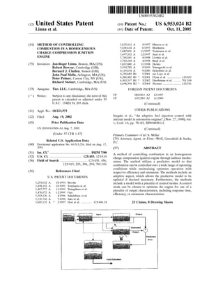
  • 1. (12) United States Patent Linna et al. (54) (75) METHOD OF CONTROLLING COMBUSTION IN A HOMOGENEOUS CHARGE COMPRESSION IGNITION ENGINE Inventors: Jan-Roger Linna, Boston, MA (US); Robert Bowyer, Cambridge (GB); Bernard J. Challen, Sussex (GB); John Paul Mello, Arlington, MA (US); Peter Palmer, Carson City, NV (US); Richard Stobart, Cambridge, MA (US) (73) Assignee: Tiax LLC, Cambridge, MA (US) ( *) Notice: Subject to any disclaimer, the term of this patent is extended or adjusted under 35 U.S.C. 154(b) by 269 days. (21) Appl. No.: 10/223,573 (22) Filed: (65) Aug. 19, 2002 Prior Publication Data (60) (51) (52) (58) (56) US 2003/0145836 A1 Aug. 7, 2003 (Under 37 CFR 1.47) Related U.S. Application Data Provisional application No. 60/313,256, filed on Aug. 17, 2001. Int. Cl? .................................................. F02M 7/00 U.S. Cl. ........................................ 123/435; 123/419 Field of Search ................................. 123/435, 436, 123/419, 295, 304, 294; 701!101 References Cited U.S. PATENT DOCUMENTS 5,253,632 A 5,458,102 A 5,467,757 A 5,476,072 A 5,503,126 A 5,535,716 A 5,605,132 A * 10/1993 10/1995 11/1995 12/1995 4/1996 7/1996 2/1997 Brooks Tomisawa et a!. Yanagihara et a!. Guy Sakakibara et a!. Sato eta!. Hori et a!. ............. 123/406.24 111111 1111111111111111111111111111111111111111111111111111111111111 EP EP US006953024B2 (10) Patent No.: (45) Date of Patent: US 6,953,024 B2 Oct. 11, 2005 5,623,412 A 5,636,614 A 5,682,856 A 5,697,332 A 5,740,045 A 5,743,244 A 5,832,880 A 5,954,783 A 6,119,654 A 6,230,683 B1 6,286,482 B1 * 6,363,317 B1 * 6,698,394 B2 * 4/1997 6/1997 11/1997 12/1997 4/1998 4/1998 11/1998 9/1999 9/2000 5/2001 9/2001 3/2002 3/2004 Masson eta!. Morikawa Tomisawa et a!. Asai eta!. Livshiz et a!. Bush eta!. Dickey Yamaguchi et a!. Heiselbetz et a!. zur Loye et a!. Flynn et a!. ................ 123/435 Druzhinina et a!. ........ 701!104 Thomas ...................... 123/241 FOREIGN PATENT DOCUMENTS 0810363 A2 12/1997 1052383 A2 11/2000 (Continued) OTHER PUBLICATIONS Inagaki et al., "An adaptive fuel injection control with internal model in automotive engines", (Nov. 27, 1990), vol. 1, Conf. 16, pp. 78-83, XP010038111. (Continued) Primary Examiner-Carl S. Miller (74) Attorney, Agent, or Firm-Wolf, Greenfield & Sacks, P.C. (57) ABSTRACT A method of controlling combustion in an homogenous charge compression ignition engine through indirect mecha- nisms. The method utilizes a predictive model so that combustion can be controlled over a wide range of operating conditions while maintaining optimum operation with respect to efficiency and emissions. The methods include an adaptive aspect, which allows the predictive model to be updated if deemed necessary. Furthermore, the methods include a model with a plurality of control modes. A control mode can be chosen to optimize the engine for one of a plurality of output characteristics, including response time, efficiency, or emissions characteristics. Fault Indication 23 Claims, 8 Drawing Sheets Prediction Error
  • 2. US 6,953,024 B2 Page 2 JP wo wo wo wo wo wo FOREIGN PATENT DOCUMENTS 11-2173 W098/10179 W099/40301 WO 99/42718 A1 W099/42718 WO 00/26526 A1 wo 01!44644 A2 1!1999 3/1998 8/1999 8/1999 8/1999 5!2000 12/2001 01HER PUBLICATIONS Magnus Christensen and Bengt Johansson, Per ArnnJus and Fabian Mauss, "Supercharged Homogeneous Charge Com- pression Ignition" 1998 Society of Automotive Engineers, Inc., Technical Papers pp. 980787 143-157. Magnus Christensen and Bengt Johansson, "Homogeneous Charge Compression Ignition with Water Injection", Society of Automated Engineers Technical Paper 1999-01-0182, Mar. 1-4, 1999. Magnus Christensen and Bengt Johansson, "Influence of Mixture Quality on Homogeneous Charge Compression Ignition", Society of Automated Engineers Technical Paper 962454, Oct. 19-22, 1998. Jurgen Willard, Rolf-Gunther Nieberding, Guide Vent and Christian Enderle, "The Knocking Syndrome-its Cure and its Potential" Society of Automated Engineers Technical Paper 982483, Oct. 19-22, 1998. Hisakazu Suzuki, Noriyuki Koike, and Matsuo Odaka, "Combusion Control Method of Homogeneous Charge Die- sel Engines" Society of Automotive Engineers, Technical Paper 980509. 1998, pp. 89-95. S. M. Aceves, J. R. Smith, C. K. Westbrook and W. J. Pitz, "Compression Ratio Effect on Methane HCCI Combustion", Journal of Engineering for Gas Turbines and Power, Jul. 1999, vol. 121, pp. 569-574. * cited by examiner
  • 3. U.S. Patent Oct. 11, 2005 Sheet 1 of 8 Input L------r------------- ' Fault Indication Figure l US 6,953,024 B2 Output Prediction Error
  • 4. U.S. Patent Fast response Oct. 11, 2005 Sheet 2 of 8 Low NOx Maximum efficiency .+ + ICost functions Figure 2 US 6,953,024 B2 :{> IActuators
  • 5. U.S. Patent Figure 3a Oct. 11, 2005 Sheet 3 of 8 OctJ= o.4 D ctJ =o.45 m cil =o.s mcil =o.55 • ctJ: 0.6 US 6,953,024 B2 Figure 3b
  • 6. U.S. Patent Oct. 11, 2005 Sheet 4 of 8 11 10 9 ~ 8 .Q :; 0 7 > "''; 6 "·a, ~ 5 ... 0 :;; 4 .a E ~ 3 Maximum Number of Engine Revolutions tolerable for Changing Engine Load at different Engine Speeds w/o being Perceived as Sluggish. US 6,953,024 B2 o~~~~~~~~~~-Y~~~~~~~~~..~~~~~~~~~ 500 1000 1500 2000 2500 3000 3500 4000 4500 5000 5500 6000 Engine Speed (RPM) Figure 4
  • 7. U.S. Patent Oct. 11, 2005 Sheet 5 of 8 US 6,953,024 B2 NOx Emissions vs Work ProdLJCed 1000 . . ..... 100 .. E0.. 10 e "'c 0 iii "'EUJ >< 0 •z 0.1 0 4 8 8 IMEP-G (bar) 10 12 14 Thermal Efficiency vs Work Produced 45 ...••. 40 35 ~ g30 ·8 "'m I ~ 25 !._ 20 15 10 0 2 4 8 IMEP-G (bar) 8 10 12 14 Figure 5
  • 8. U.S. Patent Oct. 11, 2005 Sheet 6 of 8 US 6,953,024 B2 Combustion Figure 6
  • 9. U.S. Patent Oct. 11, 2005 Sheet 7 of 8 US 6,953,024 B2 Mapping VGT rack EGR Fuel socaclual Figure 7
  • 10. U.S. Patent Oct. 11, 2005 Sheet 8 of 8 US 6,953,024 B2 Figure 8
  • 11. US 6,953,024 B2 1 METHOD OF CONTROLLING COMBUSTION IN A HOMOGENEOUS CHARGE COMPRESSION IGNITION ENGINE 2 model, and identifying a desired time for combustion. It also comprises measuring values of a plurality of engine oper- ating parameters and providing the values to the model and employing the model to define actuator control commands CROSS REFERENCE TO RELATED APPLICATIONS This application claims the benefit of U.S. Provisional Patent Application No. 60/313,256 filed Aug. 17, 2001 which is hereby incorporated by reference. s associated with start of combustion occurring at the desired time. Additionally it involves controlling the combustion in the engine with the actuator control commands; measuring an actual time for the start of combustion; and updating the model based on a difference between the desired time and 10 the actual time for the start of combustion. FIELD OF THE INVENTION In another aspect of the invention, a method of controlling combustion in a compression ignition distributed reaction engine is disclosed. The method comprises providing a model for controlling the start of combustion in a compres-This invention relates generally to a method of controlling an internal combustion engine configured to burn a pre- mixed charge of air and fuel, using auto-ignition to initiate combustion. In particular the invention relates to a predic- tive model based control system to control a process by indirect mechanisms so that combustion can be controlled 15 sian ignition distributed reaction engine. The model com- prising a plurality of control schemes for operating the engine. The method includes supplying engine speed and/or engine load requirements as inputs to the model; measuring over a wide range of operating conditions while maintaining 20 optimum operation with respect to efficiency and emissions. BACKGROUND OF THE INVENTION In a Premixed Compression Ignition (PCI) engine or Homogenous Charge Compression Ignition (HCCI) engine, 25 fuel is introduced into the cylinder prior to or early during the compression stroke, i.e. prior to movement of the piston towards top dead center (TDC). As the piston moves towards TDC during the compression stroke, the air and fuel mixture is compressed. As a consequence, the temperature and 30 pressure within the cylinder increases continuously during the compression stroke. The increasing temperature results in auto ignition of the air and fuel mixture at crank angles at or near TDC. The result is combustion characterized by a rapid cascade of detonations in different zones of the cyl- 35 inder as the piston is approaching TDC. This allows the realization of an effective expansion ratio approaching the geometric compression ratio (i.e, maximum efficiency) of the engine. Additionally, if the air and fuel mixture is sufficiently lean, the engine-out NOx and soot emissions will 40 be dramatically lower than those of typical Diesel and SI engines. values of a engine operating parameters; choosing at least one of the plurality of control schemes after evaluating the inputs and the engine speed and/or load requirements to create a chosen control scheme; and controlling the start of combustion in the engine with the chosen control scheme. In yet another aspect of the invention, a method is disclosed for controlling combustion in a CIDR engine to a desired behavior. The method comprises sensing at least one engine operating condition and predicting, based at least in part on the at least one sensed engine operating condition, an engine behavior. It further comprises setting at least one actuator to a desired set point based, at least in part, on the at least one of the predicted dynamic behavior and the chemical kinetics to obtain the desired engine behavior. Various embodiments of the present invention provide certain advantages and overcome certain drawbacks of prior control methods. Embodiments of the invention may not share the same advantages, and those that do may not share them under all circumstances. This being said, the present invention provides numerous advantages including the noted advantage of improved control of a combustion pro- cess in a HCCI engine. Further features and advantages of the present invention, as well as the steps associated with various embodiments, are described in detail below with reference to the accom-Most HCCI engines lack an actuating mechanism capable of directly regulating the start of combustion and the rate of heat release in combustion. Instead, combustion begins when the air and fuel mixture has been compressed to sufficiently high pressures and temperatures, and the pro- gression of combustion is primarily determined by the chemical kinetics of the combustion reaction 45 panying drawings. BRIEF DESCRIPTION OF THE DRAWINGS The foregoing and other objects, features and advantages of the invention will be apparent from the following more SUMMARY OF THE INVENTION The methods of the present invention are adapted to control combustion in a homogenous charge compression ignition engine. Controlling combustion includes the use of 50 particular description of preferred embodiments of the invention, as illustrated in the accompanying drawings in which like reference characters refer to the same parts throughout the different views. The drawings are not nec- essarily to scale, emphasis instead being placed upon illus- 55 trating the principles of the invention. a predictive model based control system to control the combustion process by indirect mechanisms. The control methods include adapting a model to reflect changes in the operation of the HCCI engine. They include choosing between multiple control modes to best meet the immediate 60 needs of the engine. A method may include one or more of the aforementioned aspects, each independently or in combination, contributing to improved control of combus- tion in a HCCI engine. In one aspect of the invention, a method is disclosed for 65 controlling combustion in an compression ignition distrib- uted reaction engine. The method comprises providing a FIG. 1 is a representation of predictive, look-ahead, control algorithm for CIDR engines; FIG. 2 is a schematic representation of the technique used for calculating actuator settings, and where the control system uses the most suitable cost function; FIG. 3a is a schematic representation of a practical HCCI cylinder charge composition with a mass average equiva- lence ratio of 0.5; FIG. 3b is a schematic representation of an idealized HCCI cylinder charge composition with a mass average equivalence ratio of 0.5;
  • 12. US 6,953,024 B2 3 FIG. 4 is a chart showing an example of the maximum number of engine revolutions acceptable for changing engine load at different engine speeds in order to avoid perception of sluggish or slow response; 4 2. Calculate new dynamic models for components and/or processor of the engine to be controlled. This may include the air and exhaust system, and the combustion process in the cylinder. Both structure and parameters of the model are 5 adapted. The new results are stored.FIG. 5 are two graphs showing experimentally found NOx emissions and thermal efficiency as functions of gross indicated mean effective pressure (IMEP-G), and illustrating that there are several combinations of the control parameters used in the experiment (air/fuel ratio, intake charge tem- perature and intake charge pressure) that provide stable and 10 robust engine operation, but sacrifice efficiency and/or NOx emissions; FIG. 6 is an example of a model structure to relate input conditions to the effect on combustion; FIG. 7 is a schematic diagram giving an example of the 15 control demands and intermediate signals used in a predic- tive control algorithm; and 3. Decide which cost function to utilize, or adapt a cost function to meet the particular objectives at the present time, wherein a cost function is a mathematical relationship that assist in optimization. 4. Use the cost function to optimize future control actions, and if required apply constraints to actuator movement. 5. Use the calculated control signal to update the various controlling actuators. 6. Check, using a classifier whether the new parameter details fall into one of the fault classes initially taught to the system. FIG. 8 illustrates a feature space showing four fault classes Cl to C4, with two features, f1 and f2. DETAILED DESCRIPTION A predictive, look-ahead, control algorithm for control- ling combustion in HCCI engines according to an embodi- 20 ment of the present invention, is depicted schematically in FIG. 2. The logic of this control algorithm is outlined as follows: The present invention provides optimum control of a homogeneous charge compression ignition (HCCI) engine (also referred to as a CIDR engine, as will be explained below) with respect to efficiency and emissions. They accomplish this through mechanisms that indirectly control 25 the start of combustion, and the rate of heat release in combustion. 1) The input to the engine (i.e., driver throttle position in automotive applications) is used to determine the new target engine load required. 2) Using knowledge of the maximum time-delay accept- able to avoid a sluggish response feeling for the specific engine in the specific application (e.g. 100 ms), the number of engine cycles available (n) to accomplish a significant Although not shown, the engine is similar to a conven- tional HCCI engine, except for the engine controller and associated sensors and actuators for use with the present invention. Accordingly, the engine includes a cylinder block having a cylinder and a reciprocating piston disposed therein. Various intake and exhaust valves communicate with the cylinder to deliver charge to the cylinder and exhaust by products as the engine may also include fuel and air deliver systems, and other standard systems associated with internal combustion engines. 30 change in engine load is determined. 3) Using a predictive model of the engine, which is stored and updated at each control cycle and knowledge of the current and future target operating condition identified as the engine load, the different indirect load control parameters 35 available are screened and ranked based on (A) Response Time, (B) Degree of Authority, (C) Effect on Combustion Phasing, and (D) Engine Efficiency Penalties. 4) Based on the model-based screening in Step 3, anIn one embodiment, the methods comprise the use of a predictive model used to determine appropriate controller commands by predicting engine performance associated with a plurality of controller command possibilities. Once optimum controller commands have been identified, they are implemented through actuators that are able to control combustion through indirect means. 40 optimum combination of one or more indirect control parameters giving sufficiently fast control with sufficient authority, and with minimum cross-over effects on SOC and efficiency penalties is identified. 5) Using the predictive model of the engine, a control In yet another embodiment, the methods comprise the use of a model of an HCCI engine to determine appropriate controller commands. Once controller commands have been identified and implemented, various resulting engine param- eters are measured. The controller commands and the engine parameters that resulted from the commands are then used to update the HCCI engine model if deemed necessary. 45 strategy based on the optimum combination of control parameters defined in Step 4 is determined. The control strategy includes prediction of appropriate control parameter settings cycle-by-cycle for the next n cycles such that the engine load is regulated to the target load requested by the 50 driver, while SOC is maintained near TDC. In still another embodiment, the methods comprise a model that has a plurality of control modes. One or more engine operating parameters are measured and then com- 55 pared to desired engine operating parameters. One of the plurality of control modes is then chosen based on the difference between the measured engine operating param- eters and the desired engine operating parameters. The following steps provide a broad overview of steps 60 that may be employed in an embodiment of the present invention. They describe the process of calculating a new control action, and using a predictive look-ahead algorithm and are represented schematically in FIG. 1. 1. Compute the likely future load demand. This may 65 include estimating future load and/or speed demands for the powertrain. 6) A sensor or sensors (to sense engine vibration or crankshaft angular acceleration and other parameters, or optical phenomena or a calculation where SOC is calculated from ionization or pressure information) are used to sense SOC and other engine operating characteristics such as equivalence ratio in each engine cycle and provide a feed- back signal to the predictive model for adaptive learning 7) As the engine condition changes, the predictive algo- rithm uses a cost function appropriate to either a fast response, a high efficiency operation, or a low NOx opera- tion. During times of rapid change (as predicted by the load estimation algorithm), the fast response cost function is used. This cost function penalizes error (between actual and demanded load) more than it does control effort. At small error the cost function is adjusted to improve the engine efficiency, by selecting one of the control variables as the key variable to be controlled. For example at mid range load,
  • 13. US 6,953,024 B2 5 the intake pressure may be used to control load, and it will be the error in intake pressure that is penalized. Steps 1) through 7) are repeated for every engine cycle. 6 before auto-ignition occurs. Also, when the engine is started, the air in the intake manifold may be near atmospheric pressure as a turbocharger or supercharger may not yet be operational. This can mean that less air mass will beAs previously mentioned, in a HCCI engine, fuel is introduced into the cylinder prior to or early during the compression stroke. As the piston moves towards IDC, the 5 delivered to the cylinder, making it more difficult to realize the temperatures required for the air and fuel mixture to auto-ignite. Furthermore, the need to minimize harmful pollutant emissions during such a start-up condition presents an additional constraint on the development of cold start air and fuel mixture is compressed and the temperature and pressure within the cylinder increase until auto-ignition of the air and fuel mixture occurs. The result is combustion characterized by a rapid cascade of detonations in different 10 zones of the cylinder as the piston is approaching TDC. Fuel can be introduced to the cylinder through techniques similar to those found in many conventional spark ignition engines. Perhaps the most reported method of introducing 1 15 fuel in HCCI engines is the use of traditional port fue injection (PFI). An alternative method is the direct injection (DI) of fuel during intake or early in the compression stroke. These methods of introducing fuel can provide for a well mixed air and fuel charge, however, they typically still have h 20 significant spatial variations of the air/fuel ratio through t e cylinder as shown in FIG. 3a. In particular, these variations may exist with the piston is near TDC Accordingly, the cylinder content of an HCCI engine is not likely to be perfectly homogeneous as is represented in FIG. 3b. Experimental studies have shown that the heat release rate in practical HCCI configurations is controlled by chemical kinetics, with mixing being a less significant factor. Chemi- 25 cal kinetics are the steps a reaction goes through in pro- ceeding from reactants to products. Some of the factors that 30 affect chemical kinetics include the temperature at which the reaction occurs, and the concentration of the reactants which can include the mass average equivalence ratio, the amount of exhaust gas recirculation, and the amount of injected water to name few. Consequently, the combustion process in 35 HCCI engines can be considered a distributed reaction process, as opposed to a flame propagation (as found in many SI engines) or diffusion flame (as found in many other compression ignition engines). Following from these observations, the air and fuel mix- 40 ture in the cylinder of a HCCI engine can be described as a plurality of regions, each defined by its own equivalence ratio as shown in FIG. 3a. Each of the regions can be considered a perfectly stirred reactor. The in-cylinder flow field, including the flow-field generated by the fuel jet if 45 in-cylinder direct injection is used, and the resulting mixing action can determine the size and the mixture strength distribution of these perfectly stirred reactors. However, the reaction rates within each reactor are controlled primarily by chemical kinetics. Additionally, the overall combustion 50 reaction is primarily controlled by chemical kinetics. Given these observations, a different label for HCCI engines, or other engines operating in these modes may therefore be Compression Ignition Distributed Reactions (CIDR). Hereinafter, the term CIDR is used interchangeably with the 55 term HCCI to represent engines with a more or less homo- geneous charge. Although the advantages of CIDR engines have been demonstrated in experimental programs at steady state oper- ating points, the optimization of these engines over a prac- 60 tical range of operating conditions present additional chal- lenges. Some of the technical issues to consider in practical implementations of CIDR technology include: Cold start: In CIDR engines, combustion is initiated when the air and fuel charge reaches its auto-ignition temperature. 65 When the inlet air and components are cold, a greater temperature change is required of the air and fuel charge strategies. Rate of heat release (ROHR): In conventional engines, fluid mechanic sub-processes control the rate of combustion. Such sub-processes include air-fuel mixing in diesel engines or flame wrinkling, flame stretch, and mass and thermal convection by turbulence in spark ignition engines. By contrast, the ROHR is controlled through chemical kinetics in CIDR engines, with ignition occurring spontaneously throughout the cylinder. ROHR can be controlled in CIDR engines by determining the intake charge temperature, fuel/ air ratio, and exhaust gas recirculation combinations that are sufficient for the cylinder contents to ignite over the entire engine operating map. Power density: Many CIDR engines have lower power densities because they frequently operate with lean mixtures and large amounts of charge dilution to achieve appropriate chemical kinetics. However, experiments have shown that turbocharging or supercharging can dramatically increases the attainable power density from CIDR from CIDR engines. Consequently, there exists an optimization trade-off between high boost pressure, which requires a lower com- pression ratio due to limits on peak cylinder pressure, and the thermal efficiency of the engine. To address this issue, CIDR engines can adopt a mixed-mode operating concept commonly employed for gasoline direct injection (GDI) engines. In this approach, a first mode modes operates much like a homogeneous stoichiometric spark ignition engine for high loads with maximum air utilization; and a second mode operates much like a lean homogeneous charge compression ignition mode for low load and idle operation to achieve maximum fuel economy and low NOx emissions. Start of combustion (SOC) timing: From a control standpoint, one of the most striking features of CIDR engines is that there are generally no actuating mechanisms available for directly regulating start of combustion, such as spark timing in SI engines or injection timing in diesel engines. Instead, start of combustion occurs when the fuel- air mixture has been compressed to sufficiently high pres- sures and temperatures, similar to auto-ignition or knock in SI-engines. Most engine load control parameters, such as charge energy density by temperature, pressure, or equiva- lence ratio to name a few, tend to impact the in-cylinder conditions. As a result, they may inadvertently affect when combustion begins with respect to top dead center (also known as combustion phasing) and thereby performance, efficiency and emissions. Consequently, the achievement of optimal SOC timing over a practical range of operating conditions, engine speed in particular, is a complex task. Also, coupling exists between SOC timing and many load control variables, which are issues that need to be considered in controlling the start of combustion. Controlling combustion in CIDR engines, either the start of combustion, or the rate of heat release, represents a challenge to the commercialization of CIDR engines. If auto-ignition occurs prematurely, or the rate of heat release occurs too rapidly, it can cause undue stress on the mechani- cal components and a lower thermal efficiency through a lower effective expansion ratio. Likewise, if the conditions
  • 14. US 6,953,024 B2 7 within the cylinder are not sufficient to promote auto- ignition, partial or complete misfire can occur within the cylinder resulting in very high hydrocarbon emissions and loss of power. An algorithm of the present invention is now described with reference to FIG. 1 and FIG. 2. The algorithm begins by defining a target engine load and/or speed, which is typically provided directly by the operator of the engine. For instance, in an automotive application, the position of the gas pedal provides this input. This load and/or speed infor- mation is translated into combustion requirements, such as a desired start of combustion time, and/or a desired rate of heart release by a set point generator, which are then passed to the controller. The set point generator may comprise a look up table in some embodiments of the invention. In other embodiments, the set point generator may even comprise models which define the set point through mathematical relationships instead of through lookup tables. Still, in other embodiments, the controller may directly accept speed and/ or load demands and compute the combustion requirements itself. Some embodiments of the invention may use a load prediction algorithm to help in the optimization process. The predictive control algorithm seeks to minimize future error, and a knowledge of future demand is helpful in reaching an optimal series of control actions. In such embodiments, the load prediction algorithm is based on the assumption that future control demand on the engine (speed and load) make a smooth transition based on the inertia of the underlying system. Once a target engine load and/or speed are defined, the algorithm chooses which of several control modes are used to control the engine. FIG. 4 is a graph that generally represents the maximum number of engine revolutions that are generally acceptable for changing engine load at a given engine speeds. If more time, or equivalently engine revolu- tions are taken for changing engine load, the engine response may be perceived as sluggish by the operator. For instance, the in-cylinder condition must be changed in roughly 2 engine revolutions or one engine cycle for a four-stroke engine when the engine is operating at a low engine speed (1200 rpm). Some embodiments of the invention will place 8 plant (the engine) to the controller. Such parameters may include, but are not limited to air mass flow, cam position, crank position, engine coolant temperature, load demand, intake air temperature, intake air pressure, engine speed, 5 engine load, exhaust gas temperature, exhaust gas recircu- lation valve position, amount of exhaust gas recirculation, equivalence ratio, exhaust air/fuel ratio, throttle position, valve timing, turbocharger turbine speed, NOx emission level, variable nozzle turbine setting, variable geometry 10 turbine setting, start of combustion, rate of heat release, and wastegate position as the invention as the invention is not limited in this respect. Once a control mode is chosen and the engine operating parameters are identified by the controller, it uses a predic- 15 tive model to evaluate the various actuator commands, or equivalently, the plant input that it may use to control the engine at the present engine operating parameter levels. Such actuator control commands may include, but are not limited to equivalence ratio, intake to exhaust heat- 20 exchanger bypass valve position, variable valve timing, amount of exhaust gas recirculation, variable nozzle turbine setting, variable geometry turbine setting, wastegate setting, water injection timing, water injection amount, fuel injection timing, fuel injection amount, exhaust restriction setting, 25 and electrically assisted turbocharger setting. The model of the engine can represent a plurality of engine subsystems models, such as its air inlet system, turbocharger or supercharger system, fuel delivery system, charge cooling system, exhaust system, and exhaust gas 30 recirculation system (EGR) to name a few. The model can predict the dynamic behavior of the various subsystems for various actuator control commands, and therefore can pre- dict overall engine performance. Such dynamic behaviors of these systems can include the motions of components, such 35 as predicted turbocharger speeds, predicted drivetrain speeds, and other suitable device conditions as the invention is not limited in this respect. Dynamic behaviors may also refer to the predicted states or characteristics of various engine processes, such as air or fluid transport times within 40 the engine subsystems, and heat and mass transfer behaviors within the engine subsystems to name a few. Furthermore, the chemical kinetics of the cylinder charge, such as ignition delay and thermal formation of nitrogen oxides (NOx) maya priority on avoiding such a sluggish response. In these embodiments, when a situation exists where the actual engine load is significantly different than the desired engine 45 load, or equivalently the engine load error, the controller will operate in a control mode that places a priority on a fast load response. Once the load error is reduced to a predetermined level, the controller may change to a different control mode, such as one that places a priority on low NOx emissions, or one that places a priority on maximum efficiency. FIG. 2 is be predicted by the model. The predictive model based control of the CIDR engine is more complex than controlling an engine with a direct actuating mechanism. The predictive, look-ahead model based control has models of the engine and its sub-systems that can accurately predict the dynamic behavior, such as 50 transport times and thermal inertia of all key components, and the chemical kinetics of the cylinder charge, such as ignition delay and thermal formation of nitrogen oxides (NOx)· a representative sketch of how each control mode may be used by the controller. Each mode may be said to have its own set of cost functions that are employed by the controller to run the engine. These different cost functions are associ- 55 ated with placing a priority on particular engine performance parameters of groups of such parameters. As mentioned above, such parameters may include fast load response, low NOx emissions, or maximum efficiency to name a few. FIG. 5 illustrates two examples showing that there are several 60 combinations of control parameters that provide stable engine operations but sacrifice one of engine efficiency and/or NOx emissions. In addition to receiving combustion requirement informa- tion from the set point generator, the controller may receive 65 input related to any engine operating parameters. This is represented in FIG. 1 by the line connecting the output of the The predictive algorithm uses its series of sub-models, in some cases multivariable in character to form the basis for the optimization process. For example, the intake charge pressure and EGR are related through a multivariable frame- work. A variable geometry turbocharger and an EGR valve will be used to control both the EGR rate and the charge pressure in the inlet manifold. A model of their behavior is stored ready to be used for each control calculation. An example of the format of this model is shown in FIG. 6. Two models are maintained in parallel. An air system model is used to relate VGT and EGR actuator positions and the fuelling setting to the resulting air fuel ratio (AFR). A combustion model is used to relate the charge parameters (air fuel ratio, pressure and temperature) to the combustion
  • 15. US 6,953,024 B2 9 phasing. Other models are used to represent other relation- ships in the engine as represented in FIG. 7. As previously mentioned, the control of combustion in an HCCI engine is complex because HCCI engines generally lack direct control mechanisms. Predictive model based control of SOC is helpful in addressing this lack of a direct control mechanisms. Knowledge of the steady state behavior of the engine, and the dynamic behavior contained in the model are used as a basis for calculating an optimal response to the current engine conditions. Optimal response as used here means the best response according to the chosen control mode under the current engine operating parameters. In evaluating actuator control commands, the controller applies a plurality of simulated controller commands to the model and predicts the engine output. This is accomplished by using steady state settings for the actuators, and then adding an optimal increment to each setting. The cost functions for dynamic and static optimization are used by this aspect of the algorithm to decide on control commands that relate to the engine output that is being optimized. For instance, if efficiency is being optimized the dynamic cost function will include an estimate of efficiency-and so at each time step, the control will seek to optimize efficiency. In addition to the considerations above, there exists a collection of indirect control parameters, and at any given steady state operating condition it is possible to find several combinations of these control parameters that will result in acceptable SOC timings. However, these indirect control parameters exhibit different key characteristics at different engine operating conditions such as (1) degree of authority or load control range, (2) response time, (3) effect on combustion phasing SOC, (4) impact on engine-out emissions, and (5) engine efficiency penalties. This is illus- trated in FIG. 5 which shows thermal efficiency and NOx as a function of engine load (or power) for different combina- tions of intake charge temperature, pressure and equivalence ratio. Clearly, not all control parameter combinations are equally attractive from an emissions and efficiency stand- point. An ideal load control parameter or mechanism would combine a large load control range with fast response time, and little or no cross-over effect on combustion phasing, engine-out emissions, and thermal efficiency. 10 complex objectives are reconciled by m1mm1zmg a cost function. Depending on the particular performance requirements, the nature of the cost function may be changed. In this off-line optimization process, the relative 5 importance of the various controls at each load will be identified. The relative importance will result in a mapping function which will translate generic requirements into the particular adjustments needed to effect the control change. Once a set of actuator control commands are chosen, they 10 are used to control the various actuators that may indirectly control combustion in a CIDR engine. The resulting engine operating parameters are measured, and compared to the values predicted by the model to define a prediction error. These values may include any of the previously mentioned 15 engine operating parameters, and in particular, they may include combustion characteristics, such as start of combus- tion and rate of heat release. Such combustion characteristics may be measured with accelerometer that detects vibrations associated with the combustion process, although other 20 methods for sensing the combustion process may be used as the invention is not limited in this respect. The prediction error may be evaluated through any means known to those in the art. One of such means includes a multi-mode recursive least squares step which tracks the history of the 25 square of the error. Once the prediction error is evaluated, it can be used to update the model in efforts to minimize future prediction errors as represented in FIG. 1. The model is able to use feedback signals for adaptive learning to modify characteristic parameters such as the 30 auto-ignition characteristics of fuel so that variations or disturbances can be accommodated. Such variations or dis- turbances may include changes in fuel quality and compo- sition between different fill-ups, or the gradual fouling of heat exchangers within the engine to name a few, although 35 other factors may be included as the invention is not limited in this respect. These variations and disturbances can be accounted for by changing the model. Furthermore, a clas- sification algorithm may be used in some embodiments of the invention to decide whether the underlying cause of the 40 disturbance or variation should require the attention of the engine operator. Such attention can include alerting the operator to a change in the quality of the fuel, or alerting the operator that heat the heat exchangers require maintenance although other information could be provided to the operator 45 as the present invention is not limited in this respect.Consequently, at any operating condition, there often exists one combination of control parameters that provides optimum engine operation, including high efficiency, low emissions, and good control authority. Thus, given a com- mand to change operating condition, the controller must not only find a combination of indirect control parameter set- tings that ensures proper engine operation, it must also determine what combination of parameters will change the operating condition fast enough, and with the least adverse effect on engine efficiency and emissions. Once the desired operating condition has been reached, the controller can turn 55 to optimizing for optimum engine efficiency. The predictive, model-based, look-ahead controller according to one embodiment of the present invention is a multi-variable predictive approach which will control several indirect con- trol parameters to ensure sufficiently fast and accurate con- trol of SOC with minimum adverse effect on engine effi- ciency and emissions. FIG. 8 shows an example of how the algorithm may identify such variation and disturbances (faults) including changes in delivered fuel quality. Two features that are coupled to fuel quality, f1 and f2, may be used as indexes 50 into a feature space. The classification is indicated by the area of the space. In practice there may be more than two features used. When the indexes correspond to an area associated with a particular fault, such as Cl, C2, C3, or C4, a particular alert may be provided to the engine operator. These predictive models offer several advantages over other types of control algorithms such as feedback on error only and feedforward with feedback. Unlike the feedback approaches, the predictive approach can be fast with tailored robustness and, therefore, useful for misfire avoidance. The 60 predictive approach can also be used in multi-variable form with constraints, allowing for precise load control. Furthermore, the predictive control approach can be used for accurate SOC control since future load demand can be takenEmbodiments of the control system can also store the steady state values of actuators to meet the engine's required operating parameters including efficiency and emissions. 65 Those steady state parameters will be identified by running a series of steady state conditions on a test bed. At each, the into account. Because the predictive control is formulated as an optimal control, the algorithm makes best use of the actuation energy available. Another feature is illustrated in FIG. 8 which shows a mapping process which takes the
  • 16. US 6,953,024 B2 11 controller output signals and adapts them to the particular needs of an engine. In this way the controller may be adapted to a new design or different configuration. While this invention has been particularly shown and described with references to preferred embodiments thereof, 5 it will be understood by those skilled in the art that various changes in form and details may be made therein without departing from the scope of the invention encompassed by the appended claims. What is claimed is: 10 1. A method of controlling combustion in a compression ignition distributed reaction engine to a desired behavior, the method comprising: sensing at least one engine operating condition; 15 predicting, based at least in part on the at least one sensed engine operating condition, a dynamic engine behavior; and setting at least one actuator to a desired set point based, at least in part, on the at least one of the predicted 20 dynamic behavior and the chemical kinetics to obtain the desired engine behavior, sensing a resulting engine behavior and further predicting, based at least in part on the at least one sensed engine operating condition and the resulting engine behavior, 25 at least one of the dynamic behavior of the at least one engine component or process, and chemical kinetics of an air/fuel charge; and determining whether a short response time or engine efficiency is a desired engine behavior to be achieved 30 and wherein setting the at least one actuator comprises identifying at least one actuator that, when actuated, will yield the determined desired engine behavior. 2. The method according to claim 1, wherein the dynamic behavior is one of an air transport time and a charge 35 transport time. 3. The method according to claim 1, wherein the chemical kinetics is NOx formation. 4. The method according to claim 1, wherein the chemical kinetics is ignition delay. 40 5. The method according to claim 1, wherein sensing the at least one engine operating condition comprises sensing an engine load. 6. The method according to claim 1, wherein setting the at least one actuator comprises setting the at least one 45 actuator to the desired set point within a time that is based on a number of engine rotations. 7. The method according to claim 1, wherein setting the at least one actuator comprises setting the at least one actuator within 100 milliseconds of sensing the at least one 50 engine operating condition. 8. The method according to claim 1, wherein setting the at least one actuator comprises identifying a plurality of actuators to set and identifying a subset of the plurality of actuators to set that will produce the desired engine behavior 55 within a desired response time. 9. The method according to claim 1 wherein setting the at least one actuator comprises identifying a plurality of aetna- tors to set and identifying a subset of the plurality of actuators to set that will produce the desired engine behavior 60 with a least impact on engine efficiency. 10. The method according to claim 1, wherein sensing at least one engine operating condition comprises sensing an engine throttle position. 11. The method according to claim 1, wherein sensing a 65 resulting engine behavior comprises sensing engine vibra- tion. 12 12. The method according to claim 1, wherein sensing a resulting engine behavior comprises sensing a start of com- bustion. 13. The method according to claim 1, wherein sensing a resulting engine behavior comprises sensing an angular acceleration of a crankshaft of the engine. 14. A method of controlling combustion in a compression ignition distributed reaction engine, the method comprising: providing an engine controller that includes: a plurality of control modes, including: an engine response control mode with an engine response time minimizing cost function and an engine efficiency control mode with an efficiency maximizing cost function; a model of engine operation, the model adapted to receive a plurality of sets of simulated actuator control parameters and engine operating parameters and to provide predicted engine output for each set of simulated actuator control parameters; operating the engine in the engine efficiency control mode; providing a desired engine response requirement and engine operating parameters to the controller; changing from the engine efficiency control mode to the engine response control mode when the engine effi- ciency control mode cannot meet the desired engine response requirement; evaluating a plurality of sets of actuator control param- eters by applying a corresponding plurality of sets simulated control parameters and the engine operating parameters to the model, which in turn employs the response time minimizing cost function to provide corresponding sets of predicted engine output; comparing the plurality the sets of predicted engine output with the desired engine response requirement; and controlling the engine by implementing a set of the plurality of actuator control parameters that best satis- fies the engine response time minimizing cost function. 15. The method of claim 14, wherein the desired engine response requirement is an engine speed. 16. The method of claim 14, wherein the desired engine response requirement is an engine load. 17. The method of claim 14, further comprising: measuring actual engine output and updating the model based on a difference between the predicted engine output and the actual engine output. 18. The method of claim 17, wherein the actual engine output includes an actual start of combustion time and the predicted engine output includes a predicted start of com- bustion time. 19. The method of claim 14, wherein controlling com- prises controlling the engine with the one of the plurality of actuator control parameters such that the desired engine response requirement is met within 100 milliseconds of implementing the one of the plurality of actuator control parameters. 20. The method of claim 14, wherein the plurality of engine operating parameters are chosen from the group consisting of: air mass flow signal, cam signal, crank angle signal, engine coolant temperature, load demand, intake air temperature, intake air pressure, engine speed, engine load, exhaust gas temperature, exhaust gas recirculation valve position, amount of exhaust gas recirculation, equivalence ratio, exhaust air/fuel ratio, throttle position, valve timing, turbocharger turbine speed, NOx emission level, variable
  • 17. US 6,953,024 B2 13 nozzle turbine setting, variable geometry turbine setting, and wastegate position. 21. The method of claim 14, wherein the actuator control parameters are selected from a group consisting of: equiva- lence ratio, intake to exhaust heat-exchanger bypass valve s position, variable valve timing, amount of exhaust gas recirculation, variable nozzle turbine setting, variable geom- etry turbine setting, wastegate setting, water injection, fuel injection timing, fuel injection amount, exhaust restriction, and electrically assisted turbocharger setting. 14 22. The method of claim 14, wherein the controller further comprises at least one additional control mode selected from the group consisting of: a control mode to optimize load control range, a control mode to optimize effects on com- bustion phasing of start of combustion, and a control mode to optimize engine emissions. 23. The method of claim 14, wherein the engine efficiency control mode is an engine fuel consumption control mode. * * * * *
  • 18. UNITED STATES PATENT AND TRADEMARK OFFICE CERTIFICATE OF CORRECTION PATENT NO. : 6,953,024 B2 Page 1 of 1 APPLICATIONNO. : 10/223573 DATED : October 11, 2005 INVENTOR(S) : Jan-Roger Linna et al. It is certified that error appears in the above-identified patent and that said Letters Patent is hereby corrected as shown below: On the title page, item [75], INVENTOR(S): Jan-Roger Linna, Boston, MA (US); Robert Bowyer, Cambridge, (GB); Bernard J. Challen, Sussex (GB); John Paul Mello, Arlington, MA (US); Peter Palmer, Carson City, NV (US); Richard Stobart, Cambridge, MA (US) should read, INVENTOR(S): Jan-Roger Linna, Boston, MA (US); Bernard J. Challen, Sussex (GB); John Paul Mello, Arlington, MA (US); Peter Palmer, Carson City, NV (US); Richard Stobart, Cambridge (GB) Signed and Sealed this Twenty-ninth Day ofApril, 2008 JONW.DUDAS Director ofthe United States Patent and Trademark Office