1. Electrical Substation
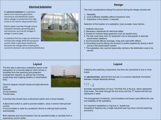
An electrical substation is a subsidiary
station of an electricity generation,
transmission and distribution system
where voltage is transformed from high
to low or the reverse using transformers.
Electric power may flow through several
substations between generating plant
and consumer, and may be changed in
voltage in several steps.
A substation that has a step-up transformer
increases the voltage while decreasing the
current, while a step-down transformer
decreases the voltage while increasing the
current for domestic and commercial distribution.
Design
The main considerations taking into account during the design process are:
1. Reliability
2. Cost (sufficient reliability without excessive cost)
3. Expansion of the station, if required.
Selection of the location of a substation must consider many factors:
1. Sufficient land area
2. Necessary clearances for electrical safety
3. Access to maintain large apparatus such as transformers.
4. The site must have room for expansion due to load growth or planned
transmission additions.
5. Environmental effects( drainage, noise and road traffic effects.
6. Grounding must be taking into account to protect passers-by during a short-
circuit in the transmission system
7. The substation site must be reasonably central to the distribution area to be
served.
Layout
The first step in planning a substation layout is the
preparation of a one-line diagram which shows in
simplified form the switching and protection
arrangement required, as well as the incoming
supply lines and outgoing feeders or transmission
lines.
One-line diagram should include principal elements:
Lines
Switches
Circuit breakers
Transformers
Incoming lines should have a disconnect switch and a circuit breaker.
A disconnect switch is used to provide isolation, since it cannot interrupt load
current.
A circuit breaker is used as a protection device to interrupt fault currents
automatically.
Both switches and circuit breakers may be operated locally or remotely from a
supervisory control center.
Layout
Following the switching components, the lines are connected to one or more
buses.
An electrical bus, derived from bus bar, is a common electrical connection
between multiple electrical devices.
Symbolic representation of a bus: The thick line is the bus, which represents
three wires. The slash through the bus arrow and the "3" means that the bus
represents 3 wires
The arrangement of switches, circuit breakers and buses used affects the cost
and reliability of the substation.
For important substations a ring bus or double bus.
Substations feeding only a single industrial load may have minimal switching
provisions.