Indian railway&metro rail,others electrical safety first periorty

India is growing Rail Transportation Infra Connecting Maximum Possible Land Connectivity Long route and Suburban Daily Passenger Travelling with in Cities Like State Connectivity ,City Local Travelling speed 70KMP to 200KMP and Fast Bullet Trains. These Infra is Full of Metal Jungle From Track ,Structures,Cables and Rolling Stocks. These Track may be Ground ,Elevated ,Under Ground and Long Tunnels now introducing some route below River . To Operate Railways Infra Traction Power ,Power for Building Infra and Various Equipment's require . Power Demand for Railways Network from Grid ,Self Power Solar Generation ,High Energy Battery Storage Systems and Others Water Supply for Equipment Washing ,Public Drinking and other use ,Disposal Of Waters now connected through Automation. The Whole System Connected Power ,Signal ,Data ,Telecom ,Traffic Routes ,Safety&Building Automation Like CCTV .Fire Alarm,Access Control , Audio Visuals, Public Address ,Telecom (Exchange ,Base Station Towers ,Wireless Network Towers ,Safety , Real Time Passenger Information Moving Displays, Platform Screen Door ,Lifts and Escalators,Ticketing &Fare Collections ,Entry and Exit of Passenger Inside Station Buildings. Electrical Safety is very important roles to performance of Equipment's Operators ,Human surrounding from Electrical Hazards. Earthing&connectivity of all Equipment's to discharge any kind of over voltages&Surges Due to Internal&External Like Lightning follow NBC2016 /RDSO Electrical/RDSO S&T Latest Technical Documents. We connect Power to various Equipment's&also Signal , Telecom ,Other Data Cables& Cable route from Indoor to Outdoor from Track , Control Rooms, Station Buildings &Substation via Power Transformers consider directly or indirectly these all are Interconnected and high Chances of Surge and Over-voltage enter into our System from Power Sources or via Data or Communication Ports to safe system maximum Low Voltages Signal ,Data or communication now change to Fiber Connectivity this help to protect our System from any surge from Data Port. Railway Technical Documents is very much up to marks but in Tender BID Selection of Components, Installation the involve TEAM Compromise with Contractors after taking Favor Directly or Indirectly &these Contractor Do Fraud mental using Substandard from supply up to installation Just for 3%-5% whole project is smash&High Value Damage occur when system fail&also public inconvenience due to Train Delay ,Stop&Cancel Route.Fire Accidents Earthing ,Lightning&Surge Protection is not a BOQ it's Design ,Engineering&Calculation ,With Selection of Components &Installation . Plz go through Presentation to now more about us visit webpage www.linkvuesystem.com LinkVue System is Technical Pool of Engineers Offering Design ,Engineering ,Calculation Supply with Installation Support. Maintenance Free Earthing Lightning Protection Systems Surge Protection Device Contact M-9811247237 manav.chandra@linkvuesystem.com

Recommended
Recommended
More Related Content
What's hot
What's hot (20)
Similar to Indian railway&metro rail,others electrical safety first periorty
Similar to Indian railway&metro rail,others electrical safety first periorty (20)
More from Mahesh Chandra Manav
More from Mahesh Chandra Manav (20)
Recently uploaded
Recently uploaded (20)
Indian railway&metro rail,others electrical safety first periorty
- 1. Speed Bhi Safety Bhi Railway&Metro Rail,Others Electrical Safety First Periorty
- 2. Link Vue System Offer Safety for Human and Assets (ALERT 24X7)
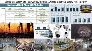
- 4. Indian Railway S&T Investment High for Safety of Passenger Indian Railways Invest Rs55,000 Crore for modernization of Signalling &Telecommunication System
- 9. Lightening and Surge Protections on Indian Railways, Study of the non-compliance/deviations from critical instructions /specifications leading to failures. Study and Analysefor possiblereasons for recent failures due to Bad Weather and Lightning SAG Professional Course Project Report On Study of Lightning,Surge Protection, Earthing for S&T InstallationsStudyby Railways and Metro Rail Project Commitee India 6KV and 12KV Earthing Wire Shield to protect Equipment’ and Human Lives from Electrical Hazards Need for Lightning and Surge Protections Sources of Transients and Surges Effective Protection Plan and Components. Components of Protection Systems RDSO and Railway Instructions and Technical Advisory Notes Provisions in RDSO Specifications Maintenance Hand books issued by CAM Tech Typical and Integrated Earthing and Bonding Plan Common Deficiencies in S&T Installations Need for Lightning and Surge Protection Systems. To Protect Equipment’s against build up of High Voltages and subsequent Damage. To ensure Safe and Reliable working of equipment’s by eliminating induced voltages To protect the Staff/Personnel working on the equipment’s against shock
- 10. Effective Lightning and Surge Protection Plan and Components Any Protection Plan should be wholistic and should cover the following components. There should not be any differentiation between Signalling and Telecom systems installed at a station and both should be integrated. The lightening strike should be captured at a preferred point referred to as A Class Protection Air Terminal on Top of the Buildings Effective Down Conductor for diverting the Lightning Energy(High Built up of Voltage) to the Ground ( Earth). Effective Earthing Arrangement for dissipating the energy so received. Surge Protection Devices further referred as SPDs of Class B, C, D as per RDSO specifications. Ensure an Equipotential Earth Plane for all Equipment’s and Sub Systems. Bonding of individual Equipment’s to the Equity Potential Earth Plane Protect Equipment’s from Surges and Transients coming from Incoming Power Lines Provisions for eliminating/limiting induced voltages to ensure Safe and Reliable working of equipment’s by Armoring/Screening of Cables carrying low voltage data and Telecom circuits and their bonding to Equipotential earth. The laying and drawing of wires/cables with adequate spacing between Clean and Dirty wires to reduce possibility of induced voltages in clean wires carrying vital circuits due to transients in Dirty wires. To minimize the effect of circulating Earth Loops
- 11. Class B & C Stage 1 and Stage 2 Protection Systems SPDs. As per RDSO/SPN/165/2012 Class B& C SPDs Stage 1 are required to be provided at the 230 Input level in TT Configuration. The class B are of Spark Gap type Voltage Switching Device tested as per IEC 61643. Similarly, Class C SPD to be provided between Line and Neutral which is a single compact varistor, a voltage clamping device and thermal disconnection type. Also, Class C SPDs Stage 2 are provided on the output side for external circuits. AS per specs the provisions of End-of-Life Indication and Potential Free Contacts are catered as below. For SPD Class B between Line and Neutral Potential Free Contact to Generate Alarm For SPD Class B between Neutral and Earth Potential Free Contact to Generate Alarm For SPD Class C between Line and Neutral Potential Free Contact to Generate Alarm Approved specifications by RDSO/SPN/215/2018 issue Date 11.02.2018 for IPS under the title “Power Supply Arrangement Level Crossing Gates/Intermediate Block Working/Intermediate Relay Hut” above features have been made Mandatory for both Class B & C. the same should be made Mandatory for IPS Specifications RDSO/SPN/165/2012. This will provide opportunity of Prewarning for replacement of a failed SPD. It was seen at MLYC station that the potential free contacts provided are not accessible for further wiring due to very close interspacing of SPDs It is recommended that the PF contacts should be prewired and made available on a row of terminals which can be easily accessed and wired to Data loggers. Another common deficiency/non-compliance of a very important provision of these specs, which is also covered under Earthing specs, TANs, Board letters is normally seen at installations i.e. “MEEB (Main Earth Equipotential Busbar) shall be installed at 20 Cms to SPD with Connecting cable length being less than 0.5 Meters without any Bends. “ Location of SPD Box: It is also recommended that the SPD box should be so located on the wall such that there is no cable ladder above it to avoid any incidence of cables on ladder burning due to any malfunctioning of SPDs causing fire. witness to one such incidence at Mantralayam station of GTL division causing total shutdown of the Panel. Use of advanced SPDs and A Class Protection Systems. With Constant research and innovation, companies are coming up with innovative solutions and constantly improving on their products. However, the efficiency and effectiveness of such advanced SPDs can only be ascertained over a period of reasonable service and availability of empirical data. Considering the Cost implications, it is suggested to use them at few Most Lighting Prone Zones.
- 12. Earthing and Equipotential Earthing and Bonding Plan. (Follow IS3043(2018),IEEE80(2013) We would like to give a substantial weightage to this MOST VITAL part of the entire Eco System of Lightening, Surge and Transients Protection Plan as most of the issues here Fraud Pertain to installation deficiencies due to unawareness of executing agencies and maintenance officials coupled with use of poor quality of materials/workmanship. Location of Earth Electrodes: The earth electrodes should be preferably located in mother soil and not high banks, made-up soil. The distance between two earth electrodes shall be maintained at 3 to 6 meters. Normally it is desired that the earth electrodes should be provided on either side of the building for Perimetric Earth. To achieve this care and coordination should happen at the stage of building construction for connectivity across the building at specified locations (same will be explained more clearly in a Typical Earthing Plan). In case it is not possible to have a Perimetric Earthing a Ring Earth should be provided on one side of the building for which adequate nonConcrete surface should be ensured to achieve 3 to 6 meters spacing between earth electrodes. It should be insisted upon and provided for while approving the Building Drawing that a provision of Plinth area of 1.5 Meters on both sides of the building shall not be concreted to cater for provision of earth electrodes. Earthing for Equipment’s is not a BOQ it’s Design ,Engineering ,Calcullation of Earth RODs and use of Ground Enhance Compound Earth for Achiving Earthing Value should be between 0.5 Ohms -1.00 Ohms Should not be Exceed from 2.00Ohms-5.00 Ohms any reason Electrodes Maintenance Free Copper Bonded Earth Electrode made up of high tensile low carbon steel rod with copper coating on outer surface. Irrespective above choices, the earth values realized will normally be function of soil resistivity, however it is preferred that for all Earths in station area should be of MF type simply because of being almost maintenance free and providing lasting connections through exothermic welding for all Burried and Permanent Earthing Connection except for Testing points Nut Bolt allowed . For outdoor application MF earths are preferred for DAC application since required earth values are <1 ohms. Ground/Earth Enhance Compound is having Important Role to perform Effective and Maintain Result for Earthing 24X7 365 Days Consiering Life 25Years these Compound should be Carbon and Lower Resistivity less than 0.02Omic ROHS , No Oxidation and Leaching Free capable to retain Moisture longer surrounding Metal Part called as Earthing ROD Provision of Loop earths and Ring/Perimetric Earth arrangements Additional Earth electrodes should be provided at 3 to 6 meters spacing and looped/interlinked with copper tapes and exothermically welded The copper tapes shall be laid at a depth of 0.5 meters This copper tape should also be covered with earth enhancing compound Whenever the distance between an Equipment Room in the same building or a separate building is more than 25 Meters,there should be a separate Earthing System
- 13. Concept of MEEB (Main Equipotential Earth Busbar) and SEEB (Sub Equipotential Earth Busbar) and BRC (Bonding Ring Perimetric) As can be seen in Fig 4 Typical Earthing and Bonding Plan There is a Perimetric Ring Earth with six Electrodes covering the Equipment (IPS) Room and Relay Room of which One electrode is termed a main electrode. It can be seen that two Perimetric earthing systems are considered for Signalling and Telecom installations with interconnection for achieving Equipotential Earth The number of Earth electrodes can be decided based on-site conditions to achieve <1-ohm values. Separate Earths are catered for Lightning Arrestors, VHF Sets, Quad Cables which are further interlinked with Perimetric Earth to achieve equipotential Earth. The Main Electrode alone is connected to MEEB Copper strip in Equipment Room Just below the SPD Box of the IPS. As per recent TAN, It is to be connected with 4 numbers of 35 Sq mm Copper cables. SEEBs are provided in Each Room directly connected to MEEB through suitable multicore copper cables.
- 14. Each Equipmentshould be directly connected to the SEEB/BRC in Star bondingconfiguration as per picture to avoid circulating Earth loops. The objective of BRC is to have a low inductance Common Bonding Network. It is not necessary that BRC has to be a closed loop. BRC can be terminated short of Doors and windows. Separate SEEB with BRC has been provided in IPS Room, Relay Room. SEEBs without BRC has been provided in Maintainer and Station Master Room Other important considerations of Earthing and Bonding Arrangements. It is preferred that connection to EEBs/BRCs shall be exothermically welded, if not Copper lugs with Spring Washers shall be used. Copper cables and Tapes of standard sizes shall be used Routing of all bonding conductors from Equipment’s to SEEB/BRC and SEEB to MEEB shall be as short as possible and separated from other wiring’. Preferably all bonding connections should be routed through floors except for earthing ladders which should be taken from BRC in a separate PVC pipe and connected to bottom of ladder.
- 15. A Class Protection Systems (Lightning Protection) IEC62305/NFC17-102 As per extant instructions from Railway Board and RDSO A class LPS are to be provided for all Electronic InterlockingInstallations of the type of Franklin Rod of 3 meters height (TAN 3006) for protection against direct lightningstrikes. There are three primary components of the A Class systems shown in Air Terminal Down Conductor Earth Grounding System The Air terminal capturesthe lightningdischarge current which is dissipated to Earth through Down conductor The Down conductor is a copper cable of adequate size. 50% of the lightning energy is transferred to the ground. It is seen that there are no standards specified for design, type of Air Terminals and Down Conductor by RDSO. Railways are using the practices as suggested by Professional and OEM’s It is recommended that RDSO shall clearly specify the complete Design, Types, Material, ProtectionCoverage for Air Terminals and Down Conductor through separate Specificationsto have uniformity and control over quality in installations. Selection of Lightning Protectionand Associate Components shpuld be Tested as per Parameters ,TestReport from Reputed LABS, Genuine and Right Components as per Application , Equipment’s and Environment Condition Indoor ,Outdoor,Under Ground. Design ,Engineering and Installationshould be prefer by Professionalsor OEM’s to ensure and Penalise if any Failure and Losses Damage Cerificate/Letter should be submitt for each installation. Periodical Maintenance should be on priorty for EffectiveProtection from Lightning
- 16. HASANPARTY(HSP) Station Case Study by S&T Failure and Reason for AS per advice of PCSTE/SCR, HSP station was inspected along with DSTE from HQ of the division, field ASTE and Section SSE and Technician, to study the possible cause of recent failures due to Lightning and Bad weather along with other deficiencies pertaining to Lightning Protections, SPDs, Earthing arrangements. It was seen that the following failures had occurred in recent past Outgoing TPR 24 V DC fuses at same location box were fused for Track Circuits 29T, 11T, 39T DN East Line HASSDAC failed and Motherboard burnt RE Cutting 24 Volts DC Signal circuit Fuse blown at Relay Rack. It is a mid_x0002_section LC Gate with IPS. Same also used for RE cutting purpose. Track Circuits failure The power cable carrying 24 V DC from Cabin to Location box was checked and properly earthed Signalling cable carrying TPR circuits was properly earthed at Cabin end and cable was meggered and values above 100 M ohms. The 24 V DC output at IPS was protected with SPD found in working condition At the Location box, it was seen that the power cable 24V DC armour earthing at GI wire was loose and not soldered. Further GI wire was also rusted . The probable cause of fuse blowing is due to ineffective earthing of the power cable armour at location end
- 17. HASSDAC failure It was seen that the 24 V DC to HASSDAC was extended from an External DCDC convertor unit (Not from the IPS Modules) which was not protected by SPD The location end Earthing and armour connectivity was found intact. The possibility of surge coming through Quad cable could not be checked as the system was changed to new quad cable laid by construction two days before our visit. It was seen that the HASSDAC motherboard was burnt at the power supply cards area It was also seen that the West Line HASSDAC supply was extended from DC-DC convertor modules of IPS protected with SPDs hence it was not failing, Only East Line HASSDAC was regularly failing. The probable cause was non protection of external supply with SPD. RE Cutting Failure The RE Cutting for Distant Signal is provided at the Relay Room of a Mid_x0002_section LC gate having its own mini IPS. The IPS provided is as per 2004 specifications with external supplies protected by MOVs and not SPDs RDSO vide its letter No STS/E/IPS. Genl Dated 02.12.2011 had advised Railways for modification by OEMs for provision of SPDs for all external supplies at pre-specified Rates. It is noticed that the required modifications were not carried out in this IPS. The Earth Value at IPS MEEB was found 3 Ohms which is on higher side. The probable cause of failure was non-protection of 24 V DC external supply by SPD and high earth resistance. Other deficiencies noticed at HSP station In both Cabins the MEEB at IPS Room and Relay Room were two separate earths without any interconnection i.e. not having an equipotential earth. The MEEB for IPS was located in Battery Room and connected to SPD of IPSwith a cable length of 10 to 15 Meters and size 10 sq mm and mixed on ladder with other wiring The 230 Supply Power cable from CLS panel to IPS was mixed with other wiring and laid on a common ladder. A single Earth was provided for both side Quad cables without interconnection to Ring Earth The BPAC and Block circuits were changed over to new quad cable without any earthing of quad armour at other end station KMPT resulting in high induced voltage of 54 Volts. The quad pairs were not twisted before terminations at either ends. Many of the outdoor Earths to location Boxes and Signals were hugely rusted and connected with GI wires.
- 18. Recommendations for Improvement The Conventional Earth Electrode It is normally seen that the conventional earth electrodes, though supplied with RITES inspection, over a short period of time gets rusted. Specially the bracket to which earth Cable/GI Wire/MS Flat are connected. Same can be seen in figures Stricter quality checks are required at Inspection Points such that the poor quality materials are rejected. It is recommended to change the design of bracket to double brackets as shown in Picture so that Two parallel connections can be made with Signalling Cable and MS Flat. Earthing Lead shall be Mild Steel Flat of size 35mmX6mm or Copper wire of 29 sq mm of cross-sectional area (19 Strands of 1.4 mm dia i.e. A 19 Core Sigg Cable or more) It is preferred that exothermic welding be made mandatory for connections to Electrodes. M S Flat Earthing Leads in addition to copper cable It is seen that in some theft prone areas copper cables are getting cut and stolen. In such a case if MS Flat earthing is provided, it will provide the required connectivity and protect the equipment’s. GI Flats with Nut Bolts and Spring washers for Cable Armour earthing in location Box in place of GI wire It is generally seen that the traditional way of earthing the cable armours in location boxes with GI wire and Soldering/Tinkering are prone to Poor and incomplete workmanship, Rusting of GI wire and therefore making the earthing ineffective inspite of the earth electrode having good earth value. The same was witnessed at HSP station causing fuse blowing. AS can be seen in the figure 14 The GI flats are drilled with adequate holes for connecting the armours of all possible cables in the location box besides having a cushion for future connections. The use of spring washers ensures firm and lasting connection. Recommendations for change in design of conventional electrodes, MS Flat earthing and GI Flat earthing in Location boxes may be considered for standard adoption by competent authorities
- 20. Link Vue System Pvt Ltd ElectricalSafety Earthing,Lightning & Surge Protection Net Working Product Supply & Installation Ethernet SW, Fiber Optics & Wire Less Automation Products Data Logger, RTU's Digital & Analog 1/0's Protocol Converter, Media Converter, Cables Connectors & LIU's Perimeter Intrusion Detection System CCTV, Fire Alarm, Access Controls & Security System Cable & Connectors, Plug & Sockets for Electrical Vehicles, Solar PV, Building Wiring I N D I A A U S T R A L I A
- 21. Link Vue SystemElectrical Safety (SurgeProtection,Lightning & Earthing )
- 23. We Mind Your Safety First All Solution for Buildings
- 25. Building Automation and Control Systems BACS has become and will continue to be increasingly common in the built environment, converging many diverse building systems as computing technology developed and connectivity became more available. Section 3 introduces the premise of Building Automation and Control Systems (BACS), including the many terms used such as Building Automation Systems (BAS), Building Management Systems (BMS), Building Energy Management System (BEMS), Intelligent Buildings (IB) and increasingly, Smart Buildings and even Smart Cities. (An automated system,where building services and processes, communicate with each other to exchange digital, analogue or other forms of information, to a central control point)
- 27. 24X7 Smart Power for All
- 30. High Energy StorageBattery Offer Long Duration Power Supply(DEMAND)
- 31. Future Power Generation and Utilities No Boundaries
- 32. Power Generation and Utilities(Industries + Domestic Purpose)
- 37. Street Light LED
- 38. Street Light LED
- 39. Fiber Optics Cables,Connectors and LIU’s
- 40. Fiber Optic Cable Network Architecture
- 41. Your Best Partner for Solution Data Communication & Networking
- 43. Safe Alarmand Secure Action Level
- 44. With Link-vue Freedom to Monitor ,Access and Control Remotely
- 45. Surge Damage Your Systems It’s Serious Topic Let Understand
- 46. Awareness,Implementaion&Maintenance of Lightning Protection along with Electrical Safety is Medatory to protect Human & Valuavle Assets Lightning strikes are the biggest natural killers in India, causing more than 2,000 deaths each year, according to the top experts from the IMD and the NDMA. India has witnessed an increasing death toll and damages due to lightning bolts over the past few years, said Mr.Rajendra Singh, Member, National Disaster Management Authority (NDMA), while addressing a national-level workshop on the issue organized by the Indian Meteorological Society, Indian Institute of Tropical Meteorology and National Centre for Medium Range Weather Forecasting. Cloud lightning Strike is "a serious threat", Mr.Mrutyunjay Mohapatra, the Director-General of India Meteorological Department (IMD), said this happens primarily due to increased exposure of people, especially farmers, fishermen and labourers who remain outdoors for reasons of livelihood. Implementation of Lightning Early Warning System and Installation of Lighting Protection System in Buildings, Telecom Towers, High Mast Lightning Poles , Transmission and Distribution Towers and specific Location High Rise Buildings is follow as per National and International Documents to Protect from Lightning to ground as per IEC62395 Conventional as well Effective Advance Lightning Protection(ESE Type) will be safe people and Assets from Lightning and Discharge with minor or negligible loss if any. Our Central Govt should declare Effective Installation of Lightning Protection ,Surge Protection and Effective Earthing under necessary Electrical Safety and advise all Director General Electrical Inspectorate to ensure by Fire and Electrical Safety Inspectors before occupancy Clearance for new Construction and also monitor Implementation of Proper maintenance to ensure perfect and healthy condition of these product and Installation. They should also mentioned mandatory of all these Govt , public and private Infrastructure to cover risk under Lightning and Fire with Insurance company 24X7 if not found and any such incident happening HOD should book in Criminal Office and recover all Human Loss and Customer Assets value from them also the responsible Fire and Safety inspector and Maintenance HOD of said premises should book under LAW. The country should have Control Room who can monitor Advance Early Lightning Threat and inform to local now capable of having 'real-time' information about lightning updated every 5 minutes to alert the people about the potential threats. Economic losses occur with cultivated fields and buildings, infrastructure like communication networks, power plants and so on, which are often destroyed by lightning strikes, and occasionally even igniting potentially devastating wildfires.
- 49. Advantages and disadvantages of the different Lightning Protection
- 50. Surge Protection Installation Important Guidline
- 51. Surge Introduction and Equipment’s Failure • Sources of Surges • A surge is a transient wave of voltageor current. The duration is not tightly specified but is usuallyless than a few milliseconds. The following are typical sources of surges: • Lightning. • Utility switching,including capacitor switching. • Equipmentswitching and switchinginductive loads • within a facility. • Protectionagainst surges is referred to as surge protection, and includes protection against bothsurge voltages and currents. The devices used to protect against surges are referredto as surge protectivedevices, or SPDs. A surge of duration longer than a few millisecondsis referred to as aswell or temporary overvoltage(TOV) and requires a differenttype of protection design; SPDs can fail if exposed to long duration TOVs. • Surge Effects • Surges can cause equipment damage. Large surges damage equipment and other components in the electrical distribution system.Smaller surges can cumulativelydamage equipment and can causenuisanceequipment tripping. Both surge voltage and current can be damaging. In the case of • lightningstrokes, the surge can be carried into a facility via all of the connectedconductive paths.There is a limit on how high of a voltage can be transmitted into a facility or residence.Above a certain level, a high voltagewill result in flashover in the insulationsystem of electrical equipment and conductors. A flashover can cause insulationdamage, electric shock, and fire. • Industry confirmed catastrophic failure or damage of electrical or electronic equipment due to a lightningevent or voltage surge and premature failure of electrical or electronic equipment,including failure of life safety equipment.
- 52. External - Atmospheric Over-Voltage (lightning)
- 53. Electrical Safety Mean Lot’s Your Equipment‘s While in Operationor in Ideal Conditions We Power all equipment’s and make safe use and protection human from Eletrical Hazard Earthing for Equipment and Body is Important and as per Electrical Equipment Cataugry Earthing Value is Define in IEEE80 ,IEC62305,NFPA, NEC and NBC2016. We Generally observe Nutral and Earthing and ensure safe operation of Equipment’s. Single Phase Line Nutral and Earthing 3Phase Line 1,Line2,Line3 , Nutral and Earthing. We are witness of Surge Travel into our System from Power Supply ,Ground and Communication Ports . These Surge reason may be Overvoltages , Transient Voltages or Lighting Direct or through Indirect sources also from Communication Cable . another reason may be Loose Contact ,Poor Jointing ,Disconnection and Short Circuit. Reason of Surge and Damage Advances in technology have caused electronics to become sensitive to voltage impulses, because : Most electronics are never totally turned off Most electronics require a good grounding and wiring system Many electronics have connections to another cable system, besides power Most electronics can be damaged by very low-level voltages that get into the circuits Micro-miniaturization in electronic systems increase sensitivity to transient effect SURGE PROTECTION SYSTEM Design with Effective Earthing as per IS3043(2018) Protection of the electrical & electronic equipment againstsurges from lightning strike or other transient effects Building with a proper lightning protection system will reduce possibilities of induced voltage surges in power or data lines Design requirement for surge protection will be coordinated with lightning protection system
- 56. Surge Protection and Earthing for Rail/Road Tunnels
- 57. Surge Protection Applications Selected by Voltage
- 58. Reason for Surge and Electrical Entrance Cataugry as per IEC
- 64. Surge is Danger Threat It’s Pick-up and Travel to System Pulse/MicroSec (10/350,8/20&1.2/50) as per UL 1449 and IEC 61643-11 Surge protection devices suppress the excess voltage, divert it safely to the ground and prevents it from causing any harm. Surge or Lightening Protector is designed to provide Line to Line protection and Line to Ground protection. Operating Voltage of the Surge or Lightening protector is greater than the normal operating voltage of the device or system to be protected. During the normal operating condition, the Surge or Lightening are non-functional as they provide a high impedance path between Lines to Ground.
- 66. Why Surge Protection Mendatory in Your Electrical Installation
- 67. Selection of Surge Protection as per Equipments Location
- 70. Surge Protection Installation Guide Line SPD for power lines 7 module full mode protection Monoblock type Not interrupt the system kA rating determine by the weakest link Enclosed in rugged,safe, all metal enclosure Provided with solid state indicators (LED) Installed in parallel Design to withstand multiple strikes SPD for data/signal Compatible & transparent to existing system Not interrupt operation system
- 72. SURGE PROTECTION SELECTION FOR POWER SYSTEM
- 73. SURGE PROTECTION SELECTION FOR PABX SYSTEM
- 74. SURGE PROTECTION SELECTION FOR FIRE ALARM SYSTEM
- 75. SURGE PROTECTION SELECTION FOR CCTV SYSTEM
- 76. SURGE PROTECTION SELECTION FOR NETWORKING SYSTEM
- 78. Marketing by Link Vue System India, Australia,Singapore,Bangladesh
- 80. Surge Protection
- 81. Surge Protection
- 82. UL Latest Documentation for SPD Year 2019
- 83. Your Answer for Queries of Surge and Lightning • What is the 10/350 waveform and how is it related to the IEC Class I SPD tests? • The 10/350 waveform is an electrical impulse produced in a laboratory by a surge impulse generator. The "10" refers to the 10 microseconds it takes the impulse to reach 90% of its peak current. The "350" refers to the time in microseconds it takes for the impulse to decay down to 50% of that peak. IEC standards state that this waveform simulates direct lightning and is based on research findings of CIGRE (International Council on Large Electrical Systems - headquartered in France). As shown elsewhere on this website both of those claims are false. Nevertheless, the IEC Class 1 Test stipulates this waveform be used to test SPDs which are to protect against direct lightning. • I've read that the 10/350 waveform is much more powerful than the other waveforms currently used in SPD testing such as the 8/20. If that's true and only spark gaps can pass those tests, then why do you oppose them? Why wouldn't we want a "stronger" SPD protectingour equipment? • The mistake we've all made is to think of the 10/350 waveform as a "powerful" impulse. Far more accurately, it should be thought of as an "irrelevant" impulse. A spark gap protector (because it responds slowly and is a crowbar device) can endure a high amplitude 10/350 waveform but doesn't do very well protecting electronic equipment from actual lightning. An MOV protector responds 1000 times faster and actually absorbs energy in the process of clamping the lightning voltage down to safe levels. MOVs don't do so well with a 10/350 waveform because they absorb part of the energy, but they far more effectively protect electronic equipment from actual lightning. CIGRE's 2013 Technical Brochure 549 has corrected the misconception that the 10/350 waveform is the waveform of a lightning first stroke--because it isn't. That is why it's accurate to call the 10/350 waveform irrelevant. We do want stronger SPDs protecting our equipment and that's why we consider it disingenuous for standards to treat MOV-based SPDs as second-class citizens when in fact they are superior at handling direct lightning. • What is the Lightning Protection Zone system and how is that related to the 10/350 waveform? • The Lightning Protection Zone (or LPZ) system is a surge protective concept that divides a structure into several "risk zones" nested within each other. The concept has been around since 1977 when E.F. Vance of the Stanford Research Institute proposed it. Here is a diagram showing Vance's risk zones, extracted from his 1977 paper "Shielding and Grounding Topology for Interference Control ." By "grounding" the outside of each shield to the inside of the adjacent shield, Vance sought to control the effect of external surges entering a facility. He also realized the need to limit the surges on the power and data lines entering the structure. Zone 0 was the external environment liable to lightning strikes. Zone 1 was the area inside the structure. • Although the purpose of the LPZ system is to mitigate the impact of incoming lightning, practically speaking, the entire function of the IEC LPZ system has become the regulation of structural and surge protective devices deemed "proper" for use in each zone. IEC international lightning protection standards adopted Vance's idea, but sabotaged it by interjecting the 10/350 waveform. In the IEC 62305 version, direct lightning (Zone 0) must be represented by a 10/350 waveform, hence only spark gap "lightning arrestors" which could pass the 10/350 Class I test were allowed to be used in Zone Zero or at locations bordering on Zone 1 (service entrance locations.) The problems with this approach are documented throughout this web, namely: 1) the CIGRE 2013 Technical Brochure 549 shows that the 10/350 waveform does not represent actual lightning, and 2) the spark gap "lightning arrestors" are intrinsically flawed. • Interestingly, although the IEC-branded LPZ system has been in widespread continuous use for over 20 years, there are apparently no statistical studies to prove its effectiveness. • More on the LPZ system can be found here.
- 84. Your Answer for Queries of Surge and Lightning • We have spark gaps installed but sometimes we've noticed that the downstream MOV protectorsburn out or our electronic control systems get damaged yet the spark gap hasn't registereda surge. What is that? • In the first case you mention, what's happening is the MOV protectors are responding faster than the spark gaps. That is easy to understand since MOVs inherently react 3 orders of magnitude faster than spark gaps. If the dinky "Class II MOV arrestors" are rated too low to handle lightning (which is always the case with the ones used together with spark gaps) then they can and do burn out before the spark gap can react. As to your equipment burning out, you need to understand that spark gaps may not respond till the voltage level reaches 2.5 kV to 3kV. A transient surge of 2.3 kV is high enough to fry your electronic equipment but not high enough to trigger the spark gap. • Was the 10/350 waveform ever a valid lightningparameter? • Unfortunately not. • Why has it taken so long to correct this situation? • You'll have to ask the members of TC 81 about this one. One possible reason is that the 10/350 waveform has always been predominantly a marketing tool and there were vested interests around making sure it was promoted and stayed in place. People who knew there was a major problem with it became afraid of speaking out against it. This could be attributed partly to the shy nature of people and partly to all the force that was employed to keep it going. But these are just opinions. • Does effective surge protection require 3 stages as the IEC standards state? • No. The reason the IEC standards required 3 stages was that spark gaps were unable to clamp overvoltages down to safe levels. They therefore had to be used together with several extra levels of MOV SPDs. A single properly sized MOV-based SPD can itself clamp overvoltages down to safe levels. That isn't to say you would never use additional stages. In critical installations a second stage is typically used as a safety factor and to handle transient voltages that are internally created (i.e. created within the facility itself) or appear on the building grounding steel. The best SPD in the world, if installed at the building entrance, would not be able to forestall damage from the overvoltages of internally-created transients. • Exaggerated ground resistance values? What does that mean? • It comes from the predilection of many surge protection companies to The most often heard "excuse" given when spark gaps failed to protect electronic equipment was "Your 5 ohm ground resistance is too high. You need to get it down to 1 ohm for your surge protection to work." This is another urban legend. Per Ohms law, (even discounting impedance which can make this situation worse) a 50kA surge going through a 1 ohm circuit will produce a voltage of 50,000 volts. This is 100 times more than could be withstood by electronic equipment. This only says that no matter how good your grounding is, to protect electronic equipment requires fast acting efficient surge protectors (which eliminates spark gaps.) •
- 85. I am Power Plug I will be Marry with only My Right Partner Make you Safety and Comfort
- 87. Electrical Power Socket IP Protection Outdoor
- 88. Electrical Socket for Indoor and Out Door Purpose
- 91. Electrical PLUG & Socket High Voltage IP 68
- 92. Electrical PLUG &Socket High Voltage IP 68
- 93. Electrical Plug & Socket High Voltage IP 68
- 94. I should Design Electrical Installation to Perform My Equipment and Safety of Mine and Other’s from Electrical Shocks Earthing Design is Not a BOQ It’s Design New Every Installation Depend on Soil Report Earthing Value should be Achive and Maintained 24X7 365Days
- 95. Earthing is Mendatory and Importance of Perfect Installations Why the need for Grounding and Bonding Equipment Protection Satisfy Warranty Requirement System Performance Service Protection Personnel Safety Voltage Difference between Two Equipment Earthing below 5 Volts Earthing Value is below 1.00 OHM for Low Voltage and 0.50 Ohms for All Other Electronic Sensitive Equipment’s
- 96. Earthing for Equipments as per Latest Electrical Safety Indian Standard
- 98. Earthing should be Eqavapotentail but use Spark Gap for Insolation
- 102. Maintenance Free Earthing Installation
- 103. Maintenance Free Earthing Value Calcullation & Costing Per PIT • BOQ Per Earthing PIT • 17.2mm Copper Bonded 3 Mtr ROD=1 • Earth Enhance Compound(Value 0.012 Ohm) Qty -30 KG • Earthing Clamp Connector for Connecting FLAT STRIP/Conductor - 01 • Earthing Strip /Conductor as per Equipment Load /Fault Current -10 Mtrs • High Quality Industrial Plastic PIT Cover
- 105. Earthing and Conductor Installation
- 106. Platform Touch Voltage Protection Membrane System
- 107. Director:- Mr. ManishKhatri Head Marketing & Sales:- Mr. Mahesh Chandra Manav Link Vue System Pvt Ltd Head Office: I-19, Karampura, New Moti Nagar, New Delhi, (India). Mobile: +91-9811247237 Tel: +91 11 4559778 Email:manav.chandra@linkvuesystem.com Email:manish@linkvuesystem.com Website: www.linkvuesystem.com Link Vue Systems Pty Ltd 2 BRUCE STREET, BLACKTOWN NSW 2148, Sydney, Australia Mobile:+61-423064098, Mobile: +91-9811247237, Email:manav.chandra@linkvuesystem.com visit webpage www.linkvuesystem.com 50