
Recommended
More Related Content
Similar to M. FLORENCE DAYANA/unit - II logic gates and circuits.pdf
Similar to M. FLORENCE DAYANA/unit - II logic gates and circuits.pdf (20)
More from Dr.Florence Dayana
More from Dr.Florence Dayana (20)
Recently uploaded
Recently uploaded (20)
M. FLORENCE DAYANA/unit - II logic gates and circuits.pdf
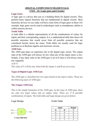
- 1. (DIGITAL COMPUTER FUNDAMENTALS) UNIT – II ( Logic gates and Circuits) Logic Gates A logic gate is a device that acts as a building block for digital circuits. They perform basic logical functions that are fundamental to digital circuits. Most electronic devices we use today will have some form of logic gates in them. For example, logic gates can be used in technologies such as smartphones, tablets or within memory devices. Truth Table A truth table is a tabular representation of all the combinations of values for inputs and their corresponding outputs. It is a mathematical table that shows all possible outcomes that would occur from all possible scenarios that are considered factual, hence the name. Truth tables are usually used for logic problems as in Boolean algebra and electronic circuits. AND Gate The AND gate plays an important role in the digital logic circuit. The output state of the AND gate will always be low when any of the inputs states is low. Simply, if any input value in the AND gate is set to 0, then it will always return low output(0). A.B=Y The value of Y will be true when both the inputs A and B are set to true. Types of Digital Logic AND Gate The AND gate is classified into two types based on the input it takes. These are the following types of AND gate: The 2-input AND Gate This is the simple formation of the AND gate. In this type of AND gate, there are only two input values and an output value. There are 22 =4 possible combinations of inputs. The truth table and logic design are given below: Logic Design Truth Table
- 2. The 3-input AND Gate Unlike 2-input AND gate, the 3-input AND gate have three inputs. The Boolean expression of the logic AND gate is defined as the binary operation dot(.). The AND gate can be cascaded together to form any number of individual inputs. There are 23 =8 possible combinations of inputs. The truth table and logic design is given below: Logic Design Truth Table OR Gate The OR gate is a mostly used digital logic circuit. The output state of the OR gate will always be low when both of the inputs states is low. Simply, if any input value in the OR gate is set to 1, then it will always return high-level output(1). The logic or Boolean expression for the OR gate is the logical addition of inputs denoted by plus sign(+) as A+B=Y The value of Y will be true when one of the inputs is set to true. Types of Digital Logic AND Gate Just like AND gate, the OR gate is also classified into two types based on the input it takes. These are the following types of OR gate: The 2-input OR gate This is the simple form of the OR gate. In this type of OR gate, there are only two input values and an output value. There are 22 =4 possible combinations of inputs. The truth table and logic design are given below: Logic Design
- 3. Truth Table The 3-input OR gate Just like AND gate, the OR gate can also have any number of individual inputs. The Boolean expression of the logical OR gate is defined as the binary operation plus(+). Like AND gate, OR gate can also be cascaded together to form any number of individual inputs. There are 23 =8 possible combinations of inputs. The truth table and logic design are given below: Logic Design Truth Table NOT Gate The NOT gate is the most basic logic gate of all other logic gates. NOT gate is also known as an inverter or an inverting Buffer. NOT gate only has one input and one output. When the input signal is "Low", the output signal is "High" and when the input signal is "High", the output is "Low". The Boolean expression for the NOT gate is as follows: A'=Y When A is not true, then Y is true The standard NOT gate is given a symbol that is shaped like a triangle with a circle at the end, pointing to the right. This circle is known as an "invert bubble" and is used to represent the logical operation of the NOT function in the NOT, NAND and NOR symbols in their output. Logic Design Truth Table The complement value is generated by the NOT
- 4. gate. The NOT gate is so-called because when the input signal is 0, the output signal will NOT be 0, Similarly, when the input signal is 1, the output signal will NOT be 1. In the NOT gate, the bubble denotes the single inversion of the output signal. But this bubble can also exist on the gate's input to indicate an active-less input. This reversal of the input signal is not limited only to the NOT gate, but can also be used on any digital circuit or gate, as shown with the operation of inversion, whether it is at the input or output terminals. The easiest way is to think of the bubble as an inverter. NAND Gate The NAND gate is a special type of logic gate in the digital logic circuit. The NAND gate is the universal gate. It means all the basic gates such as AND, OR, and NOT gate can be constructed using a NAND gate. The NAND gate is the combination of the NOT-AND gate. The output state of the NAND gate will be low only when all the inputs are high. Simply, this gate returns the complement result of the AND gate. The logic or Boolean expression for the NAND gate is the complement of logical multiplication of inputs denoted by a full stop or a single dot as (A.B)'=Y The value of Y will be true when any one of the input is set to 0. Types of Digital Logic AND Gate The NAND gate is also classified into two types based on the input it takes. These are the following types of AND gate: The 2-input NAND Gate This is the simple formation of the NAND gate. In this type of NAND gate, there are only two input values and an output value. There are 22 =4 possible combinations of inputs. The truth table and logic design are given below:
- 5. The 3-input NAND Gate Unlike the 2-input NAND gate, the 3-input NAND gate has three inputs. The Boolean expression of the logic NAND gate is defined as the binary operation dot(.). The NAND gate can be cascaded together to form any number of individual inputs. There are 23 =8 possible combinations of inputs. The truth table and logic design are given below: NOR Gate The NOR gate is also a universal gate. So, we can also form all the basic gates using the NOR gate. The NOR gate is the combination of the NOT-OR gate. The output state of the NOR gate will be high only when all of the inputs are low. Simply, this gate returns the complement result of the OR gate. The logical or Boolean expression for the NOR gate is the complement of logical multiplication of inputs denoted by the plus sign as (A+B)'=Y The value of Y will be true when all of its inputs are set to 0. The 2-input NOR gate Just like other gates, it is also a simple form of the NOR gate. In this type of NOR gate, there are only two input values and an output value. There are 22 =4 possible combinations of inputs. The truth table and logic design are given below:
- 6. XOR gate or Exclusive-OR gate. The XOR gate stands for the Exclusive-OR gate. This gate is a special type of gate used in different types of computational circuits. Apart from the AND, OR, NOT, NAND, and NOR gate, there are two special gates, i.e., Ex-OR and Ex- NOR. These gates are not basic gates in their own and are constructed by combining with other logic gates. Their Boolean output function is significant enough to be considered as a complete logic gate. The XOR and XNOR gates are the hybrids gates. The 2-input OR gate is also known as the Inclusive-OR gate because when both inputs A and B are set to 1, the output comes out 1(high). In the Ex-OR function, the logic output "1" is obtained only when either A="1" or B="1" but not both together at the same time. Simply, the output of the XOR gate is high(1) only when both the inputs are different from each other. The plus(+) sign within the circle is used as the Boolean expression of the XOR gate. So, the symbol of the XOR gate is ⨁. This Ex-OR symbol also defines the "direct sum of sub-objects" expression. These are the following types of Exclusive-OR gate: 2-input Ex-OR gate This is a simple form of the hybrid gate XOR. In this type of XOR gate, there are only two input values and an output value. There are 22 =4 possible combinations of inputs. The output level is high when both inputs are set to a different logic level. The Boolean expression of 2-input XOR gate is as follows:
- 7. Exclusive NOR Gate The Exclusive NOR gate is also known as the XNOR gate or Ex-NOR gate. It performs the operation same as XOR gate followed by NOT gate, thus it is abbreviated as XNOR gate. The exclusive NOR gate is the combination of the exclusive OR gate and the NOT gate. Thus, the operation of the XNOR gate is reciprocal of the XOR gate. The exclusive NOR gate gives the output as 1 when both inputs are identical. I.e., either both inputs are 1’s or 0’s. The output of the XNOR is high(.i.e., 1) for the input combinations like 11 or 00. Input Output A B A XNOR B 0 0 1 0 1 0 1 0 0 1 1 1 Input Output A B Y 0 0 0 0 1 1 1 0 1 1 1 0