chapter 5.pptx: drainage and irrigation engineering
slides_12_ch 14-2- complex numbers.pdf
1. The Basic Elements and Phasors
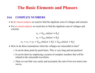
14.6 COMPLEX NUMBERS
In dc circuit analysis we need to find the algebraic sum of voltages and currents
For ac circuit analysis we need also to find the algebraic sum of voltages and
currents.
How to do these summations when the voltages are sinusoidal in time?
o It can be done point by point basis. This is very long and not practical
o It can be done by employing a system of complex numbers that will be
related to the sinusoidal waveform.
o Then we can find very easily and accurately the sum of two (or more) sine
waves.
2. A complex number represents a point in
a two-dimensional plane located with
reference to two distinct axes.
This point can also determine a radius
vector drawn from the origin to the point.
The symbol j (or sometimes i) is used to
denote the imaginary component
Two forms are used to represent a
complex number: rectangular and polar
3. 14.7 RECTANGULAR FORM
The rectangular form is:
Boldface ≡ vector (magnitude and
direction)
Italic ≡ magnitude only
5. 14.8 POLAR FORM
The polar form is:
Z ≡ magnitude only always positive
≡ angle measured counter-clockwise
(CCW) from the positive real axis
Angle measured clockwise must have a
minus sign associated
12. Complex Conjugate
The conjugate or complex conjugate of a complex number can be found by simply
changing the sign of the imaginary part in the rectangular form or by using the
negative of the angle of the polar form:
The conjugate of:
is
29. A better method uses the rotating radius vector (used to generate the sine wave)
This radius vector:
has a constant magnitude
one end is fixed at the origin
is the phasor when applied to electric circuit
30.
31. We can find the sum ( v1+v2 ) using their phasors and
The phasors are added using the complex number algebra to obtain the phasor form
of the sum vT = v1+v2 very easily and then convert it back to sinusoidal form.
Position of the various phasors, is called phasor diagram.
It is actually a “snapshot” of the rotating vector at t = 0
32.
33. Because the rms values are more used in ac circuits then in all future notations:
The phasor used will have magnitude equal to the effective (rms) value of
the sign wave it represents.
and
Where V and I are the rms values and is the phase angle.
Time domain Phasor domain