Installation of Sensors and Data loggers at project site
Summer placement in Brunel University
1. Iordanis
Karapanagiotis
1
Summer
placement
in
Brunel
University
Introduction
and
Project
Description
During
summer
of
2014,
I
completed
7
weeks
of
work
along
PhD
students
Svetlin
Isaev
and
Mohannad
Jreissat,
under
the
supervision
of
Dr
Harris
Makatsoris.
Their
project
involved
a
modular
flow
reactor1
for
the
production
of
biodiesel
and
other
substances.
The
flow
rate
of
the
reactants
is
controlled
through
six
C3000
Tricontinent
OEM
precision
pump
modules.
These
pumps
are
connected
to
a
PC
via
RS-‐232
communication
and
relevant
hardware,
so
that
the
flow
rate
is
easily
controlled
by
entering
the
appropriate
command.
My
part
in
this
project
was
to
understand
how
the
flow
is
controlled
and
what
has
already
been
achieved.
Furthermore,
for
the
improvement
of
some
parameters
of
the
products
(homogeneity),
a
heating
system
was
proposed,
were
temperature
can
be
monitored
and
controlled
with
the
use
of
a
heat
exchanger.
A
temperature
monitoring
system
for
this
heat
exchanger
was
developed.
Procedure
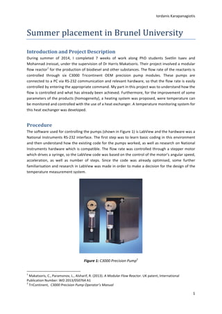
The
software
used
for
controlling
the
pumps
(shown
in
Figure
1)
is
LabView
and
the
hardware
was
a
National
Instruments
RS-‐232
interface.
The
first
step
was
to
learn
basic
coding
in
this
environment
and
then
understand
how
the
existing
code
for
the
pumps
worked,
as
well
as
research
on
National
Instruments
hardware
which
is
compatible.
The
flow
rate
was
controlled
through
a
stepper
motor
which
drives
a
syringe,
so
the
LabView
code
was
based
on
the
control
of
the
motor’s
angular
speed,
acceleration,
as
well
as
number
of
steps.
Since
the
code
was
already
optimised,
some
further
familiarisation
and
research
in
LabView
was
made
in
order
to
make
a
decision
for
the
design
of
the
temperature
measurement
system.
Figure
1:
C3000
Precision
Pump2
1
Makatsoris,
C.,
Paramonov,
L.,
Alsharif,
R.
(2013).
A
Modular
Flow
Reactor.
UK
patent,
International
Publication
Number:
WO
2013/050764
A1
2
TriContinent,
C3000
Precision
Pump
Operator’s
Manual
2. Iordanis
Karapanagiotis
2
It
was
suggested
that
the
best
way
to
implement
the
temperature
measurement
systems
was
either
using
an
Arduino
microcontroller
or
by
making
a
custom
made
Printed
Circuit
Board
(PCB).
Some
experimentation
with
the
Arduino
Uno
platform
controlled
through
LabView
led
to
the
conclusion
that
it
would
be
rather
tedious
to
design
it
in
this
way.
As
a
result,
and
also
for
learning
purposes,
it
was
suggested
to
design
and
build
a
PCB
using
the
Peripheral
Interface
Controller
PIC16F819.
The
design
procedure
for
the
PCB
is
outlined
below:
1. Identify
the
parameter
that
needs
to
be
measured
(i.e.
temperature)
and
search
for
appropriate
sensors.
The
sensors
used
were
three
MCP9700
thermistor
IC’s,
as
temperature
needs
to
be
measured
at
three
different
locations.
The
choice
of
this
type
of
sensor
is
justified
by
the
fact
that
they
come
as
an
integrated
package,
so
no
extra
circuitry
is
needed
for
amplification
or
cold
junction
compensation.
2. Do
research
on
how
to
construct
the
electronic
connections
and
then
draw
the
circuit
on
paper.
Each
thermistor
has
three
terminals:
one
for
the
supply
voltage
(5V
battery),
one
for
ground
and
one
for
the
output
voltage.
Also,
a
100nF
capacitor
should
be
connected
between
the
output
voltage
of
each
thermistor
and
the
ground.
The
output
voltage
is
connected
to
an
analogue
I/O
pin
on
the
microcontroller.
3. Verify
the
circuit
performance
on
a
breadboard.
4. Create
the
circuit
on
appropriate
software
(Circuit
Wizard).
An
extra
4-‐pin
SIL
connector
is
added
to
the
circuit
for
a
Bluetooth
communication
with
the
PC.
5. The
schematic
circuit
is
converted
into
a
PCB
layout
with
the
aid
of
the
software.
The
components
are
arranged
more
neatly,
and
the
file
is
sent
for
printing.
Below
is
shown
the
schematic
circuit
and
the
PCB
layout
on
Circuit
Wizard:
Figure
2:
Circuit
diagram
of
the
temperature
measurement
system
3. Iordanis
Karapanagiotis
3
Figure
3:
PCB
layout
for
the
temperature
measurement
system
When
the
board
was
printed
(Figure
4),
the
individual
components
(PIC,
capacitors
and
terminal
connectors)
were
placed
at
the
appropriate
locations
and
soldered
(Figure
5).
The
battery
and
thermistors
are
connected
to
their
terminals,
as
well
as
the
Bluetooth
transmitter.
Figure
4:
Printed
board
(unpopulated)
Figure
5:
Printed
board
with
soldered
components
After
the
hardware
is
ready,
the
program
needs
to
be
uploaded
to
the
PIC.
It
is
in
CCS
C
and
is
uploaded
using
MPLAB
and
the
MPLAB
ICD
3
in-‐circuit
debugger.
The
code
is
shown
below:
4. Iordanis
Karapanagiotis
4
Outcome,
Discussion
and
Further
Improvements
When
the
Bluetooth
communication,
thermistors
and
battery
are
connected
to
the
PCB,
the
board
and
battery
pack
started
to
get
hot,
which
suggested
that
a
short
circuit
is
present.
After
checking
all
the
terminals
with
a
voltmeter,
it
was
concluded
that
the
PCB
tracks
are
too
thin
(i.e.
positive
and
ground
track
are
very
close
to
each
other)
and
soldering
might
have
created
a
short
circuit
between
them.
The
location
of
this
is
quite
difficult
to
spot
even
with
the
aid
of
magnifying
glasses,
so
the
best
solution
is
to
build
the
PCB
again
using
thicker
tracks.
The
electronics
do
not
appear
to
be
faulty,
as
the
circuit
has
been
tested
on
a
breadboard
and
the
temperature
was
measured
successfully
with
the
correct
calibration
of
the
sensors
through
the
program.
Also,
the
Bluetooth
communication
was
established
normally
and
the
temperature
was
displayed
on
the
PC
screen.
5. Iordanis
Karapanagiotis
5
Furthermore,
the
thermistors
are
attached
to
the
board
via
small
breadboards
so
that
they
are
not
damaged
when
soldered
(Figure
6).
Of
course,
this
is
practical
only
for
testing
purposes,
as
the
sensors
need
to
be
inserted
into
the
reactor
through
small
passages
of
diameter
roughly
the
size
of
the
thermistor
head.
This
creates
the
need
for
the
legs
of
the
thermistor
to
be
directly
connected
to
the
wires
by
soldering.
However,
this
might
damage
the
sensor
due
to
excessive
heat,
so
extra
care
should
be
taken
if
they
are
assembled
again.
Figure
6:
Thermistor
and
wires
soldered
on
breadboard
The
idea
of
a
temperature
measuring
system
was
suggested
because
of
the
need
of
a
heat
exchanger.
The
heat
exchanger
would
provide
the
right
temperature
to
the
reactants
in
order
to
optimise
some
properties
of
the
products.
This
can
be
achieved
by
measuring
the
actual
temperature
and
feeding
back
the
signal
to
a
controller,
in
order
to
maintain
a
desired
value
by
estimating
the
error.
Conclusion
In
conclusion,
a
temperature
measurement
device
was
designed
and
built,
which
comprised
of
three
temperature
sensors,
a
battery
pack,
a
PCB
and
a
Bluetooth
communication
board.
The
testing
of
the
system
on
the
breadboard
proved
that
it
functionally
measures
temperature
at
three
different
locations
and
displays
their
value
on
the
PC
screen.
When
the
system
was
manufactured,
some
technical
issues
with
the
PCB
suggested
that
it
should
be
rebuilt
with
thicker
tracks.
As
future
work,
this
system
can
be
embedded
into
a
heat
exchanger
system
that
controls
the
temperature
of
the
reactor
by
taking
measurements
at
three
different
locations.
This
summer
placement
was
very
useful
in
combining
knowledge
in
electronics,
coding
and
control
and
implementing
them
on
real
engineering
problems.
My
practical
skills
were
enhanced
and
the
whole
learning
procedure
proved
to
be
a
good
testing
of
my
background
knowledge
from
university.
6. Iordanis
Karapanagiotis
6
Acknowledgments
I
would
like
to
express
my
sincere
gratitude
to
Dr
Harris
Makatsoris
for
accepting
me
for
this
opportunity
to
work
under
his
supervision.
Also,
I
am
particularly
grateful
for
the
assistance
given
by
PhD
students
of
this
project
Svetlin
Isaev
and
Mohannad
Jreissat.
Advice
given
by
Dr
Antonio
Vilches
has
been
a
great
help
in
completing
the
project
and
assistance
provided
by
lab
technicians
was
greatly
appreciated.