SlideShare a Scribd company logo
1 of 6
Download to read offline
Summary
Seasoned experts in additive manufacturing (AM)
design their parts in an optimized way for the production
method. This means, that they try to avoid support
structures wherever it is possible and choose self-
supporting geometries. But even the greatest ingenuity
does not necessarily prevent from the use of supports.
Some characteristics are simply impossible to build
without. The real challenge is to create such elements
smart and efficient. Designing support structures
therefore is an art form in itself.
The Art of supporting
metal AM parts
by Stefan Bindl, EOS GmbH
This whitepaper is for
you if you are
→→ Designing metal AM parts
→→ Seeking to design your support
generation smarter
→→ Looking to reduce your
post-build processing time
Whitepaper
2
Nowadays building metal parts by additive manufacturing
requires a tremendous amount of support structures
as the designs in most cases do not really address AM
requirements. But even with specific designs for additive
manufacturing some support structures may be necessary.
Besides the boundary conditions, there are always the
same requirements for suitable support structures:
→→ Easy to remove
→→ Strong enough to hold the part
→→ Short build time
→→ Material saving
The Art of
supporting
metal AM parts
Indeed every AM engineer who is dealing with this topic
for a while knows about those. The only question arising is,
how can we get the conflict of aims solved or at least find
a suitable trade off?
By using a demo part we want to give an idea on the “Art
of supporting metal AM parts”.
Let us start with the part first: This is a design study for
a combustion chamber used in aircraft or helicopter gas
turbine engines. The entire design was dedicated to the
manufacturing method of AM, requiring virtually no
overhangs to be supported or any other geometries that
would feature any kind of support structures (see figure 1).
So far so good.
Design Study of an annular
combustion chamber
with differently shaped air inlets
3
Integration of ­attachment points
Now as there was no opportunity to integrate the adjacent
module, the turbine casing, into this part some attachment
points had to be integrated. In an ideal world we would
have a closer look on the nozzle guide vane to see how we
can make use of additive manufacturing to combine both
components or at least create an advanced interface. For
this case, let’s assume for some reasons we have to stick
to the already predefined attachment points of the turbine
casing. Augmenting those, the combustion chamber could
look like this.
Design optimization to reduce
­supported ­surfaces
Now it is relatively obvious, that these overhangs will need
support structures and as they are very high above the
building platform they need to be connected to the part.
What could be done from the design was to modify the
down facing surface a bit. As this surface is going to be
rough even if using support structures we can make the
best out of it and use the surface to ensure the bolts and
nuts will not loosen during usage. In this case, some sharp
ripplets have been introduced to realize the functional
surface. In addition the support structures can be reduced
as the exposed area per layer is reduced as well. Figure 3
illustrates the new design.
Annular combustor with mounting devices
to attach to the turbine casing
Detailed view of the attachment points and the ripped downward facing area
4
From obvious to smart supports
The most important question still remains open – how
can we realize the support structure in a smart way?
As can be derived from the design, the removal of the
support structures within this small gap underneath the
attachment points would require high efforts. In order to
solve this problem an additional part was created, with the
purpose of holding the supports and make it possible to
remove them. This additional block features two bottom
surfaces to be connected to the part and the top surface
to be the basis for the support holding the attachment
geometry. The block itself is designed to be self-supported
and does not require any additional supports.
Speaking about the smart way of building supports this
block has one key feature. Inside it comprises an internal
hexagon to be able to twist it after the built breaking the
supports and getting them out.
In addition to this functional integrated support assistant
some conventional support structures have to be designed.
Therefore one of the various supporting tools can be
utilized. In this case Materialise Magics was used to create
block supports.
The support in between the combustor and the support
block was designed in a way that it just holds the ripplets
in place and conducts the heat. At this location no strong
support and no really sophisticated connection to the part
is needed as the shackle grows out of the surrounding
walls of the burner.
On the other hand the support beneath the support block
needs to hold the block and withstand the impacting
recoating forces during the build. Having a circular
combustion chamber there are always some supports
and support blocks angled in a disadvantageous position.
Hence, the two supports, one on each side, feature a finer
hatch distance compared to the upper support in order to
make them stronger.
Both block supports, the upper and the lower, feature teeth
to the combustion chamber and closed walls and border
walls without teeth to the support block. This is because of
the later removal. Due to the weaker connection with the
combustion chamber it is supposed to break there and not
at the support block. As the entire supports will be broken
by twisting them an increased teeth height contributes
positively to the ease of removal.
CAD created support block featuring self-supporting geometry (left) and hexagon hole (right)
5
Setting up the exposure is also a crucial step within this
support generation. The kind of exposure assigned has a
significant influence on the performance of the support
and the buildability of the part in total. The following
modifications have been made to successfully build the
part and being able to remove the support structures
afterwards.
The upper support, as it can be weak, was set to a lower
energy level to reduce the connected surface on the one
hand and to make the walls more fragile on the other. The
two lower supports have been built with the standard
EOS_External_Support parameter
The support block itself is waste material and therefore
does not need to feature highest material properties.
Therefore, the hatch distance was increased to speed up
the process by reducing laser tracks and in addition the
contours have been disabled. This has a positive effect
on build time as well as the recoater contact is decreased
because of the reduced energy introduction at the parts
borders.
In order to identify a suitable configuration of support
geometry and process parameters it might be useful to
build some test parts to evaluate different settings. In this
case this was done on an EOS M 290 (see figure 7) and the
results have been transferred to the EOS M 400 on which
the combustion chamber was finally built (fig. 8).
Additional support block featuring all support structures for the build
Getting the support out by an Allen key
Dr Stefan Bindl
EOS
In 2005, Stefan Bindl graduated in aerospace engineering
at the Technical University of Munich. He complemented
his engineering studies with practical experience at several
different research facilities focused on propulsion systems.
He undertook his diploma thesis on at the Institute of Jet
Propulsion at the University of the German Federal Armed
Forces in Munich, and continued working there until 2015,
first as research assistant until his doctorate in 2010,
then as team leader for the engine test facility and finally,
Stefan Bindl was professor for aircraft engine dynamics. In
2015 he joined EOS.
Contact: stefan.bindl@eos.info
EOS GmbH
Electro Optical Systems
Corporate Headquarters
Robert-Stirling-Ring 1
82152 Krailling/Munich
Germany
Phone +49 89 893 36-0
Fax +49 89 893 36-285
www.eos.info
Status 02/2017. Technical data subject to change without notice.
EOS is certified according to ISO 9001.
EOS® and e-Manufaturing® are registered trademarks of EOS GmbH in some countries.
For more information visit www.eos.info/trademarks.
Share your ideas,
remarks and comments
with us!
email@eos.info

More Related Content

What's hot

Design Modification and Analysis of Automobile Wheel Rim using Finite Element...
Design Modification and Analysis of Automobile Wheel Rim using Finite Element...Design Modification and Analysis of Automobile Wheel Rim using Finite Element...
Design Modification and Analysis of Automobile Wheel Rim using Finite Element...ijsrd.com
 
Chapter 29
Chapter 29Chapter 29
Chapter 29mcfalltj
 
Final Chassis Report 2010
Final Chassis Report 2010Final Chassis Report 2010
Final Chassis Report 2010Thomas Ayres
 
Diagrids the language of the modern day builder
Diagrids the language of the modern day builderDiagrids the language of the modern day builder
Diagrids the language of the modern day builderSaketh Katakam
 
Analysis of diagrid structure in comparison with exterior braced frame structure
Analysis of diagrid structure in comparison with exterior braced frame structureAnalysis of diagrid structure in comparison with exterior braced frame structure
Analysis of diagrid structure in comparison with exterior braced frame structureeSAT Journals
 
Design and Structural Analysis of Alloy Wheels for Light Weight Vehicles
Design and Structural Analysis of Alloy Wheels for Light Weight Vehicles Design and Structural Analysis of Alloy Wheels for Light Weight Vehicles
Design and Structural Analysis of Alloy Wheels for Light Weight Vehicles iosrjce
 
IRJET- Analysis of Diagrid Structure
IRJET-  	  Analysis of Diagrid StructureIRJET-  	  Analysis of Diagrid Structure
IRJET- Analysis of Diagrid StructureIRJET Journal
 
Horseshoe Casino Construction
Horseshoe Casino ConstructionHorseshoe Casino Construction
Horseshoe Casino ConstructionRedBuilt LLC
 

What's hot (13)

Design Modification and Analysis of Automobile Wheel Rim using Finite Element...
Design Modification and Analysis of Automobile Wheel Rim using Finite Element...Design Modification and Analysis of Automobile Wheel Rim using Finite Element...
Design Modification and Analysis of Automobile Wheel Rim using Finite Element...
 
Car Rim or Rim
Car Rim or RimCar Rim or Rim
Car Rim or Rim
 
Chapter 29
Chapter 29Chapter 29
Chapter 29
 
Final Chassis Report 2010
Final Chassis Report 2010Final Chassis Report 2010
Final Chassis Report 2010
 
Diagrids the language of the modern day builder
Diagrids the language of the modern day builderDiagrids the language of the modern day builder
Diagrids the language of the modern day builder
 
Analysis of diagrid structure in comparison with exterior braced frame structure
Analysis of diagrid structure in comparison with exterior braced frame structureAnalysis of diagrid structure in comparison with exterior braced frame structure
Analysis of diagrid structure in comparison with exterior braced frame structure
 
Slipform
SlipformSlipform
Slipform
 
Design and Structural Analysis of Alloy Wheels for Light Weight Vehicles
Design and Structural Analysis of Alloy Wheels for Light Weight Vehicles Design and Structural Analysis of Alloy Wheels for Light Weight Vehicles
Design and Structural Analysis of Alloy Wheels for Light Weight Vehicles
 
McGill Metric CAMROL Bearings brochure
McGill Metric CAMROL Bearings brochureMcGill Metric CAMROL Bearings brochure
McGill Metric CAMROL Bearings brochure
 
IRJET- Analysis of Diagrid Structure
IRJET-  	  Analysis of Diagrid StructureIRJET-  	  Analysis of Diagrid Structure
IRJET- Analysis of Diagrid Structure
 
Flat slab
Flat slabFlat slab
Flat slab
 
Horseshoe Casino Construction
Horseshoe Casino ConstructionHorseshoe Casino Construction
Horseshoe Casino Construction
 
Formwork
FormworkFormwork
Formwork
 

Similar to EOS Whitepaper - Additive Manufacturing Supports

IRJET- Chassis Design & Analysis
IRJET-  	  Chassis Design & AnalysisIRJET-  	  Chassis Design & Analysis
IRJET- Chassis Design & AnalysisIRJET Journal
 
ME1670-IndividualReport.pdf
ME1670-IndividualReport.pdfME1670-IndividualReport.pdf
ME1670-IndividualReport.pdfVirajPahwa
 
Design auto lamp with mould dimension
Design auto lamp with mould dimensionDesign auto lamp with mould dimension
Design auto lamp with mould dimensionHuy Dickens
 
DESIGN OF FIXTURE OF CONNECTING ROD FOR BORING OPERATION
DESIGN OF FIXTURE OF CONNECTING ROD FOR BORING OPERATIONDESIGN OF FIXTURE OF CONNECTING ROD FOR BORING OPERATION
DESIGN OF FIXTURE OF CONNECTING ROD FOR BORING OPERATIONijsrd.com
 
DESIGN AND ANALYSIS OF HEAVY VEHICLE CHASSIS USING HONEY COMB STRUCTURE
DESIGN AND ANALYSIS OF HEAVY VEHICLE CHASSIS USING HONEY COMB STRUCTUREDESIGN AND ANALYSIS OF HEAVY VEHICLE CHASSIS USING HONEY COMB STRUCTURE
DESIGN AND ANALYSIS OF HEAVY VEHICLE CHASSIS USING HONEY COMB STRUCTUREIjripublishers Ijri
 
Training on Structural designing by CADD centre
Training on Structural designing by CADD centreTraining on Structural designing by CADD centre
Training on Structural designing by CADD centreyashvant meena
 
Integrated wheelhub technicalpaper-eurobrake2019
Integrated wheelhub technicalpaper-eurobrake2019Integrated wheelhub technicalpaper-eurobrake2019
Integrated wheelhub technicalpaper-eurobrake2019RaphaelLeibl
 
DESIGN AND DEVELOPMENT OF MACHINING FIXTURE FOR BD65 FINAL DRIVE CASE ON HORI...
DESIGN AND DEVELOPMENT OF MACHINING FIXTURE FOR BD65 FINAL DRIVE CASE ON HORI...DESIGN AND DEVELOPMENT OF MACHINING FIXTURE FOR BD65 FINAL DRIVE CASE ON HORI...
DESIGN AND DEVELOPMENT OF MACHINING FIXTURE FOR BD65 FINAL DRIVE CASE ON HORI...IAEME Publication
 
BAJA -Chassis Fixture for Manufacturing
BAJA -Chassis Fixture for ManufacturingBAJA -Chassis Fixture for Manufacturing
BAJA -Chassis Fixture for ManufacturingIJAEMSJORNAL
 
Matt Baum Design Engineer Portfolio
Matt Baum Design Engineer PortfolioMatt Baum Design Engineer Portfolio
Matt Baum Design Engineer PortfolioMatthew Baum
 
Design Portfolio Rev A 2017
Design Portfolio Rev A 2017Design Portfolio Rev A 2017
Design Portfolio Rev A 2017Jason Constant
 
3 Strategies for Robust Modeling in Creo Parametric
3 Strategies for Robust Modeling in Creo Parametric3 Strategies for Robust Modeling in Creo Parametric
3 Strategies for Robust Modeling in Creo ParametricEvan Winter
 
ST Blade Rev Eng_Electric_Power_11
ST Blade Rev Eng_Electric_Power_11ST Blade Rev Eng_Electric_Power_11
ST Blade Rev Eng_Electric_Power_11Eugene Chisely
 
Optimized Design and Analysis of Pedestal Bearing House
Optimized Design and Analysis of Pedestal Bearing HouseOptimized Design and Analysis of Pedestal Bearing House
Optimized Design and Analysis of Pedestal Bearing HouseIRJET Journal
 
Analysis and Structural Optimization of a Mechanical Component for the Heavy ...
Analysis and Structural Optimization of a Mechanical Component for the Heavy ...Analysis and Structural Optimization of a Mechanical Component for the Heavy ...
Analysis and Structural Optimization of a Mechanical Component for the Heavy ...Alessandro Musu
 
Design and analysis of jig and welding fixture
Design and analysis of jig and welding fixtureDesign and analysis of jig and welding fixture
Design and analysis of jig and welding fixturesagmech24
 

Similar to EOS Whitepaper - Additive Manufacturing Supports (20)

IRJET- Chassis Design & Analysis
IRJET-  	  Chassis Design & AnalysisIRJET-  	  Chassis Design & Analysis
IRJET- Chassis Design & Analysis
 
NEW SYNOPSIS
NEW SYNOPSISNEW SYNOPSIS
NEW SYNOPSIS
 
Chassis design for baja sae
Chassis design for baja saeChassis design for baja sae
Chassis design for baja sae
 
Design For Assembly
Design For AssemblyDesign For Assembly
Design For Assembly
 
ME1670-IndividualReport.pdf
ME1670-IndividualReport.pdfME1670-IndividualReport.pdf
ME1670-IndividualReport.pdf
 
Design auto lamp with mould dimension
Design auto lamp with mould dimensionDesign auto lamp with mould dimension
Design auto lamp with mould dimension
 
DESIGN OF FIXTURE OF CONNECTING ROD FOR BORING OPERATION
DESIGN OF FIXTURE OF CONNECTING ROD FOR BORING OPERATIONDESIGN OF FIXTURE OF CONNECTING ROD FOR BORING OPERATION
DESIGN OF FIXTURE OF CONNECTING ROD FOR BORING OPERATION
 
DESIGN AND ANALYSIS OF HEAVY VEHICLE CHASSIS USING HONEY COMB STRUCTURE
DESIGN AND ANALYSIS OF HEAVY VEHICLE CHASSIS USING HONEY COMB STRUCTUREDESIGN AND ANALYSIS OF HEAVY VEHICLE CHASSIS USING HONEY COMB STRUCTURE
DESIGN AND ANALYSIS OF HEAVY VEHICLE CHASSIS USING HONEY COMB STRUCTURE
 
Training on Structural designing by CADD centre
Training on Structural designing by CADD centreTraining on Structural designing by CADD centre
Training on Structural designing by CADD centre
 
Integrated wheelhub technicalpaper-eurobrake2019
Integrated wheelhub technicalpaper-eurobrake2019Integrated wheelhub technicalpaper-eurobrake2019
Integrated wheelhub technicalpaper-eurobrake2019
 
DESIGN AND DEVELOPMENT OF MACHINING FIXTURE FOR BD65 FINAL DRIVE CASE ON HORI...
DESIGN AND DEVELOPMENT OF MACHINING FIXTURE FOR BD65 FINAL DRIVE CASE ON HORI...DESIGN AND DEVELOPMENT OF MACHINING FIXTURE FOR BD65 FINAL DRIVE CASE ON HORI...
DESIGN AND DEVELOPMENT OF MACHINING FIXTURE FOR BD65 FINAL DRIVE CASE ON HORI...
 
BAJA -Chassis Fixture for Manufacturing
BAJA -Chassis Fixture for ManufacturingBAJA -Chassis Fixture for Manufacturing
BAJA -Chassis Fixture for Manufacturing
 
Optical Mount Project
Optical Mount ProjectOptical Mount Project
Optical Mount Project
 
Matt Baum Design Engineer Portfolio
Matt Baum Design Engineer PortfolioMatt Baum Design Engineer Portfolio
Matt Baum Design Engineer Portfolio
 
Design Portfolio Rev A 2017
Design Portfolio Rev A 2017Design Portfolio Rev A 2017
Design Portfolio Rev A 2017
 
3 Strategies for Robust Modeling in Creo Parametric
3 Strategies for Robust Modeling in Creo Parametric3 Strategies for Robust Modeling in Creo Parametric
3 Strategies for Robust Modeling in Creo Parametric
 
ST Blade Rev Eng_Electric_Power_11
ST Blade Rev Eng_Electric_Power_11ST Blade Rev Eng_Electric_Power_11
ST Blade Rev Eng_Electric_Power_11
 
Optimized Design and Analysis of Pedestal Bearing House
Optimized Design and Analysis of Pedestal Bearing HouseOptimized Design and Analysis of Pedestal Bearing House
Optimized Design and Analysis of Pedestal Bearing House
 
Analysis and Structural Optimization of a Mechanical Component for the Heavy ...
Analysis and Structural Optimization of a Mechanical Component for the Heavy ...Analysis and Structural Optimization of a Mechanical Component for the Heavy ...
Analysis and Structural Optimization of a Mechanical Component for the Heavy ...
 
Design and analysis of jig and welding fixture
Design and analysis of jig and welding fixtureDesign and analysis of jig and welding fixture
Design and analysis of jig and welding fixture
 

More from Machine Tool Systems Inc.

The Artistry of the Grinding Universe - Invitation 2018
The Artistry of the Grinding Universe - Invitation 2018The Artistry of the Grinding Universe - Invitation 2018
The Artistry of the Grinding Universe - Invitation 2018Machine Tool Systems Inc.
 
Point of Care - EOS Additive Manufacturing with Selective Laser Sintering - ...
Point of Care  - EOS Additive Manufacturing with Selective Laser Sintering - ...Point of Care  - EOS Additive Manufacturing with Selective Laser Sintering - ...
Point of Care - EOS Additive Manufacturing with Selective Laser Sintering - ...Machine Tool Systems Inc.
 
United Grinding Universe Event - April 18th - 19th, 2018 - save the date
United Grinding Universe Event - April 18th - 19th, 2018 - save the dateUnited Grinding Universe Event - April 18th - 19th, 2018 - save the date
United Grinding Universe Event - April 18th - 19th, 2018 - save the dateMachine Tool Systems Inc.
 
GF Machining Solutions - Rconnect Industry 4.0
GF Machining Solutions - Rconnect Industry 4.0GF Machining Solutions - Rconnect Industry 4.0
GF Machining Solutions - Rconnect Industry 4.0Machine Tool Systems Inc.
 
Ariane Aerospace - Production of an injection head for rocket engines using E...
Ariane Aerospace - Production of an injection head for rocket engines using E...Ariane Aerospace - Production of an injection head for rocket engines using E...
Ariane Aerospace - Production of an injection head for rocket engines using E...Machine Tool Systems Inc.
 
Amada Machine Tools America - CNC Surface and Profile Grinder - Open House in...
Amada Machine Tools America - CNC Surface and Profile Grinder - Open House in...Amada Machine Tools America - CNC Surface and Profile Grinder - Open House in...
Amada Machine Tools America - CNC Surface and Profile Grinder - Open House in...Machine Tool Systems Inc.
 
GF Machining Solutions - Automotive Applications
GF Machining Solutions - Automotive ApplicationsGF Machining Solutions - Automotive Applications
GF Machining Solutions - Automotive ApplicationsMachine Tool Systems Inc.
 
GF Machining Solutions - Mikron Form P Series Milling Machines
GF Machining Solutions - Mikron Form P Series Milling MachinesGF Machining Solutions - Mikron Form P Series Milling Machines
GF Machining Solutions - Mikron Form P Series Milling MachinesMachine Tool Systems Inc.
 
GF Machining Solutions - Agie Charmilles Drill 300 Series - Hole Drilling EDM
GF Machining Solutions - Agie Charmilles Drill 300 Series - Hole Drilling EDMGF Machining Solutions - Agie Charmilles Drill 300 Series - Hole Drilling EDM
GF Machining Solutions - Agie Charmilles Drill 300 Series - Hole Drilling EDMMachine Tool Systems Inc.
 
GF Machining Solutions - Agie Charmilles Drill 20 Series - Hole Drilling EDM
GF Machining Solutions - Agie Charmilles Drill 20 Series - Hole Drilling EDMGF Machining Solutions - Agie Charmilles Drill 20 Series - Hole Drilling EDM
GF Machining Solutions - Agie Charmilles Drill 20 Series - Hole Drilling EDMMachine Tool Systems Inc.
 
GF Machining Solutions - Agie Charmilles CUT P Series - Wire EDM
GF Machining Solutions - Agie Charmilles CUT P Series - Wire EDMGF Machining Solutions - Agie Charmilles CUT P Series - Wire EDM
GF Machining Solutions - Agie Charmilles CUT P Series - Wire EDMMachine Tool Systems Inc.
 
GF Machining Solutions - Agie Charmilles CUT E Series - Wire EDM
GF Machining Solutions - Agie Charmilles CUT E Series - Wire EDMGF Machining Solutions - Agie Charmilles CUT E Series - Wire EDM
GF Machining Solutions - Agie Charmilles CUT E Series - Wire EDMMachine Tool Systems Inc.
 
GF Machining Solutions - Agie Charmilles Form P Series - Die Sinking EDM
GF Machining Solutions - Agie Charmilles Form P Series - Die Sinking EDMGF Machining Solutions - Agie Charmilles Form P Series - Die Sinking EDM
GF Machining Solutions - Agie Charmilles Form P Series - Die Sinking EDMMachine Tool Systems Inc.
 
GF Machining Solutions - Agie Charmilles Form E Series - Die Sinking EDM
GF Machining Solutions - Agie Charmilles Form E Series - Die Sinking EDMGF Machining Solutions - Agie Charmilles Form E Series - Die Sinking EDM
GF Machining Solutions - Agie Charmilles Form E Series - Die Sinking EDMMachine Tool Systems Inc.
 
United Grinding - Walter Grinders - CNC Tool Grinder - Top Loader Automation
United Grinding - Walter Grinders - CNC Tool Grinder - Top Loader AutomationUnited Grinding - Walter Grinders - CNC Tool Grinder - Top Loader Automation
United Grinding - Walter Grinders - CNC Tool Grinder - Top Loader AutomationMachine Tool Systems Inc.
 
EOS P396 SLS user - Plus Medica OT - CAD engineering and production of orthoses
EOS P396 SLS user - Plus Medica OT - CAD engineering and production of orthosesEOS P396 SLS user - Plus Medica OT - CAD engineering and production of orthoses
EOS P396 SLS user - Plus Medica OT - CAD engineering and production of orthosesMachine Tool Systems Inc.
 
EOS DMLS - Case Study: Topology Optimization & Additive Manufacturing of Actu...
EOS DMLS - Case Study: Topology Optimization & Additive Manufacturing of Actu...EOS DMLS - Case Study: Topology Optimization & Additive Manufacturing of Actu...
EOS DMLS - Case Study: Topology Optimization & Additive Manufacturing of Actu...Machine Tool Systems Inc.
 
GF Machining Solutions - Microlution - Perfect Walls and Edges enable new pro...
GF Machining Solutions - Microlution - Perfect Walls and Edges enable new pro...GF Machining Solutions - Microlution - Perfect Walls and Edges enable new pro...
GF Machining Solutions - Microlution - Perfect Walls and Edges enable new pro...Machine Tool Systems Inc.
 
GF Machining Solutions - Microlution - Model ML5
GF Machining Solutions - Microlution - Model ML5GF Machining Solutions - Microlution - Model ML5
GF Machining Solutions - Microlution - Model ML5Machine Tool Systems Inc.
 

More from Machine Tool Systems Inc. (20)

EOS Whitepaper - C & A Tool Quality
EOS Whitepaper - C & A Tool QualityEOS Whitepaper - C & A Tool Quality
EOS Whitepaper - C & A Tool Quality
 
The Artistry of the Grinding Universe - Invitation 2018
The Artistry of the Grinding Universe - Invitation 2018The Artistry of the Grinding Universe - Invitation 2018
The Artistry of the Grinding Universe - Invitation 2018
 
Point of Care - EOS Additive Manufacturing with Selective Laser Sintering - ...
Point of Care  - EOS Additive Manufacturing with Selective Laser Sintering - ...Point of Care  - EOS Additive Manufacturing with Selective Laser Sintering - ...
Point of Care - EOS Additive Manufacturing with Selective Laser Sintering - ...
 
United Grinding Universe Event - April 18th - 19th, 2018 - save the date
United Grinding Universe Event - April 18th - 19th, 2018 - save the dateUnited Grinding Universe Event - April 18th - 19th, 2018 - save the date
United Grinding Universe Event - April 18th - 19th, 2018 - save the date
 
GF Machining Solutions - Rconnect Industry 4.0
GF Machining Solutions - Rconnect Industry 4.0GF Machining Solutions - Rconnect Industry 4.0
GF Machining Solutions - Rconnect Industry 4.0
 
Ariane Aerospace - Production of an injection head for rocket engines using E...
Ariane Aerospace - Production of an injection head for rocket engines using E...Ariane Aerospace - Production of an injection head for rocket engines using E...
Ariane Aerospace - Production of an injection head for rocket engines using E...
 
Amada Machine Tools America - CNC Surface and Profile Grinder - Open House in...
Amada Machine Tools America - CNC Surface and Profile Grinder - Open House in...Amada Machine Tools America - CNC Surface and Profile Grinder - Open House in...
Amada Machine Tools America - CNC Surface and Profile Grinder - Open House in...
 
GF Machining Solutions - Automotive Applications
GF Machining Solutions - Automotive ApplicationsGF Machining Solutions - Automotive Applications
GF Machining Solutions - Automotive Applications
 
GF Machining Solutions - Mikron Form P Series Milling Machines
GF Machining Solutions - Mikron Form P Series Milling MachinesGF Machining Solutions - Mikron Form P Series Milling Machines
GF Machining Solutions - Mikron Form P Series Milling Machines
 
GF Machining Solutions - Agie Charmilles Drill 300 Series - Hole Drilling EDM
GF Machining Solutions - Agie Charmilles Drill 300 Series - Hole Drilling EDMGF Machining Solutions - Agie Charmilles Drill 300 Series - Hole Drilling EDM
GF Machining Solutions - Agie Charmilles Drill 300 Series - Hole Drilling EDM
 
GF Machining Solutions - Agie Charmilles Drill 20 Series - Hole Drilling EDM
GF Machining Solutions - Agie Charmilles Drill 20 Series - Hole Drilling EDMGF Machining Solutions - Agie Charmilles Drill 20 Series - Hole Drilling EDM
GF Machining Solutions - Agie Charmilles Drill 20 Series - Hole Drilling EDM
 
GF Machining Solutions - Agie Charmilles CUT P Series - Wire EDM
GF Machining Solutions - Agie Charmilles CUT P Series - Wire EDMGF Machining Solutions - Agie Charmilles CUT P Series - Wire EDM
GF Machining Solutions - Agie Charmilles CUT P Series - Wire EDM
 
GF Machining Solutions - Agie Charmilles CUT E Series - Wire EDM
GF Machining Solutions - Agie Charmilles CUT E Series - Wire EDMGF Machining Solutions - Agie Charmilles CUT E Series - Wire EDM
GF Machining Solutions - Agie Charmilles CUT E Series - Wire EDM
 
GF Machining Solutions - Agie Charmilles Form P Series - Die Sinking EDM
GF Machining Solutions - Agie Charmilles Form P Series - Die Sinking EDMGF Machining Solutions - Agie Charmilles Form P Series - Die Sinking EDM
GF Machining Solutions - Agie Charmilles Form P Series - Die Sinking EDM
 
GF Machining Solutions - Agie Charmilles Form E Series - Die Sinking EDM
GF Machining Solutions - Agie Charmilles Form E Series - Die Sinking EDMGF Machining Solutions - Agie Charmilles Form E Series - Die Sinking EDM
GF Machining Solutions - Agie Charmilles Form E Series - Die Sinking EDM
 
United Grinding - Walter Grinders - CNC Tool Grinder - Top Loader Automation
United Grinding - Walter Grinders - CNC Tool Grinder - Top Loader AutomationUnited Grinding - Walter Grinders - CNC Tool Grinder - Top Loader Automation
United Grinding - Walter Grinders - CNC Tool Grinder - Top Loader Automation
 
EOS P396 SLS user - Plus Medica OT - CAD engineering and production of orthoses
EOS P396 SLS user - Plus Medica OT - CAD engineering and production of orthosesEOS P396 SLS user - Plus Medica OT - CAD engineering and production of orthoses
EOS P396 SLS user - Plus Medica OT - CAD engineering and production of orthoses
 
EOS DMLS - Case Study: Topology Optimization & Additive Manufacturing of Actu...
EOS DMLS - Case Study: Topology Optimization & Additive Manufacturing of Actu...EOS DMLS - Case Study: Topology Optimization & Additive Manufacturing of Actu...
EOS DMLS - Case Study: Topology Optimization & Additive Manufacturing of Actu...
 
GF Machining Solutions - Microlution - Perfect Walls and Edges enable new pro...
GF Machining Solutions - Microlution - Perfect Walls and Edges enable new pro...GF Machining Solutions - Microlution - Perfect Walls and Edges enable new pro...
GF Machining Solutions - Microlution - Perfect Walls and Edges enable new pro...
 
GF Machining Solutions - Microlution - Model ML5
GF Machining Solutions - Microlution - Model ML5GF Machining Solutions - Microlution - Model ML5
GF Machining Solutions - Microlution - Model ML5
 

Recently uploaded

Tamil Call Girls Bhayandar WhatsApp +91-9930687706, Best Service
Tamil Call Girls Bhayandar WhatsApp +91-9930687706, Best ServiceTamil Call Girls Bhayandar WhatsApp +91-9930687706, Best Service
Tamil Call Girls Bhayandar WhatsApp +91-9930687706, Best Servicemeghakumariji156
 
Double Revolving field theory-how the rotor develops torque
Double Revolving field theory-how the rotor develops torqueDouble Revolving field theory-how the rotor develops torque
Double Revolving field theory-how the rotor develops torqueBhangaleSonal
 
Hostel management system project report..pdf
Hostel management system project report..pdfHostel management system project report..pdf
Hostel management system project report..pdfKamal Acharya
 
Bridge Jacking Design Sample Calculation.pptx
Bridge Jacking Design Sample Calculation.pptxBridge Jacking Design Sample Calculation.pptx
Bridge Jacking Design Sample Calculation.pptxnuruddin69
 
Engineering Drawing focus on projection of planes
Engineering Drawing focus on projection of planesEngineering Drawing focus on projection of planes
Engineering Drawing focus on projection of planesRAJNEESHKUMAR341697
 
Generative AI or GenAI technology based PPT
Generative AI or GenAI technology based PPTGenerative AI or GenAI technology based PPT
Generative AI or GenAI technology based PPTbhaskargani46
 
XXXXXXXXXXXXXXXXXXXXXXXXXXXXXXXXXXXXXXXXXXXXXXXXXXXX
XXXXXXXXXXXXXXXXXXXXXXXXXXXXXXXXXXXXXXXXXXXXXXXXXXXXXXXXXXXXXXXXXXXXXXXXXXXXXXXXXXXXXXXXXXXXXXXXXXXXXXXX
XXXXXXXXXXXXXXXXXXXXXXXXXXXXXXXXXXXXXXXXXXXXXXXXXXXXssuser89054b
 
Kuwait City MTP kit ((+919101817206)) Buy Abortion Pills Kuwait
Kuwait City MTP kit ((+919101817206)) Buy Abortion Pills KuwaitKuwait City MTP kit ((+919101817206)) Buy Abortion Pills Kuwait
Kuwait City MTP kit ((+919101817206)) Buy Abortion Pills Kuwaitjaanualu31
 
scipt v1.pptxcxxxxxxxxxxxxxxxxxxxxxxxxxxxxxxxxxxxxxxxxxxxxxxxxxxxxxxxxxxxxxxx...
scipt v1.pptxcxxxxxxxxxxxxxxxxxxxxxxxxxxxxxxxxxxxxxxxxxxxxxxxxxxxxxxxxxxxxxxx...scipt v1.pptxcxxxxxxxxxxxxxxxxxxxxxxxxxxxxxxxxxxxxxxxxxxxxxxxxxxxxxxxxxxxxxxx...
scipt v1.pptxcxxxxxxxxxxxxxxxxxxxxxxxxxxxxxxxxxxxxxxxxxxxxxxxxxxxxxxxxxxxxxxx...HenryBriggs2
 
Bhubaneswar🌹Call Girls Bhubaneswar ❤Komal 9777949614 💟 Full Trusted CALL GIRL...
Bhubaneswar🌹Call Girls Bhubaneswar ❤Komal 9777949614 💟 Full Trusted CALL GIRL...Bhubaneswar🌹Call Girls Bhubaneswar ❤Komal 9777949614 💟 Full Trusted CALL GIRL...
Bhubaneswar🌹Call Girls Bhubaneswar ❤Komal 9777949614 💟 Full Trusted CALL GIRL...Call Girls Mumbai
 
Air Compressor reciprocating single stage
Air Compressor reciprocating single stageAir Compressor reciprocating single stage
Air Compressor reciprocating single stageAbc194748
 
Hazard Identification (HAZID) vs. Hazard and Operability (HAZOP): A Comparati...
Hazard Identification (HAZID) vs. Hazard and Operability (HAZOP): A Comparati...Hazard Identification (HAZID) vs. Hazard and Operability (HAZOP): A Comparati...
Hazard Identification (HAZID) vs. Hazard and Operability (HAZOP): A Comparati...soginsider
 
Learn the concepts of Thermodynamics on Magic Marks
Learn the concepts of Thermodynamics on Magic MarksLearn the concepts of Thermodynamics on Magic Marks
Learn the concepts of Thermodynamics on Magic MarksMagic Marks
 
HAND TOOLS USED AT ELECTRONICS WORK PRESENTED BY KOUSTAV SARKAR
HAND TOOLS USED AT ELECTRONICS WORK PRESENTED BY KOUSTAV SARKARHAND TOOLS USED AT ELECTRONICS WORK PRESENTED BY KOUSTAV SARKAR
HAND TOOLS USED AT ELECTRONICS WORK PRESENTED BY KOUSTAV SARKARKOUSTAV SARKAR
 
Thermal Engineering Unit - I & II . ppt
Thermal Engineering  Unit - I & II . pptThermal Engineering  Unit - I & II . ppt
Thermal Engineering Unit - I & II . pptDineshKumar4165
 
Navigating Complexity: The Role of Trusted Partners and VIAS3D in Dassault Sy...
Navigating Complexity: The Role of Trusted Partners and VIAS3D in Dassault Sy...Navigating Complexity: The Role of Trusted Partners and VIAS3D in Dassault Sy...
Navigating Complexity: The Role of Trusted Partners and VIAS3D in Dassault Sy...Arindam Chakraborty, Ph.D., P.E. (CA, TX)
 
DC MACHINE-Motoring and generation, Armature circuit equation
DC MACHINE-Motoring and generation, Armature circuit equationDC MACHINE-Motoring and generation, Armature circuit equation
DC MACHINE-Motoring and generation, Armature circuit equationBhangaleSonal
 

Recently uploaded (20)

Integrated Test Rig For HTFE-25 - Neometrix
Integrated Test Rig For HTFE-25 - NeometrixIntegrated Test Rig For HTFE-25 - Neometrix
Integrated Test Rig For HTFE-25 - Neometrix
 
Tamil Call Girls Bhayandar WhatsApp +91-9930687706, Best Service
Tamil Call Girls Bhayandar WhatsApp +91-9930687706, Best ServiceTamil Call Girls Bhayandar WhatsApp +91-9930687706, Best Service
Tamil Call Girls Bhayandar WhatsApp +91-9930687706, Best Service
 
Double Revolving field theory-how the rotor develops torque
Double Revolving field theory-how the rotor develops torqueDouble Revolving field theory-how the rotor develops torque
Double Revolving field theory-how the rotor develops torque
 
Hostel management system project report..pdf
Hostel management system project report..pdfHostel management system project report..pdf
Hostel management system project report..pdf
 
Bridge Jacking Design Sample Calculation.pptx
Bridge Jacking Design Sample Calculation.pptxBridge Jacking Design Sample Calculation.pptx
Bridge Jacking Design Sample Calculation.pptx
 
Engineering Drawing focus on projection of planes
Engineering Drawing focus on projection of planesEngineering Drawing focus on projection of planes
Engineering Drawing focus on projection of planes
 
FEA Based Level 3 Assessment of Deformed Tanks with Fluid Induced Loads
FEA Based Level 3 Assessment of Deformed Tanks with Fluid Induced LoadsFEA Based Level 3 Assessment of Deformed Tanks with Fluid Induced Loads
FEA Based Level 3 Assessment of Deformed Tanks with Fluid Induced Loads
 
Generative AI or GenAI technology based PPT
Generative AI or GenAI technology based PPTGenerative AI or GenAI technology based PPT
Generative AI or GenAI technology based PPT
 
XXXXXXXXXXXXXXXXXXXXXXXXXXXXXXXXXXXXXXXXXXXXXXXXXXXX
XXXXXXXXXXXXXXXXXXXXXXXXXXXXXXXXXXXXXXXXXXXXXXXXXXXXXXXXXXXXXXXXXXXXXXXXXXXXXXXXXXXXXXXXXXXXXXXXXXXXXXXX
XXXXXXXXXXXXXXXXXXXXXXXXXXXXXXXXXXXXXXXXXXXXXXXXXXXX
 
Cara Menggugurkan Sperma Yang Masuk Rahim Biyar Tidak Hamil
Cara Menggugurkan Sperma Yang Masuk Rahim Biyar Tidak HamilCara Menggugurkan Sperma Yang Masuk Rahim Biyar Tidak Hamil
Cara Menggugurkan Sperma Yang Masuk Rahim Biyar Tidak Hamil
 
Kuwait City MTP kit ((+919101817206)) Buy Abortion Pills Kuwait
Kuwait City MTP kit ((+919101817206)) Buy Abortion Pills KuwaitKuwait City MTP kit ((+919101817206)) Buy Abortion Pills Kuwait
Kuwait City MTP kit ((+919101817206)) Buy Abortion Pills Kuwait
 
scipt v1.pptxcxxxxxxxxxxxxxxxxxxxxxxxxxxxxxxxxxxxxxxxxxxxxxxxxxxxxxxxxxxxxxxx...
scipt v1.pptxcxxxxxxxxxxxxxxxxxxxxxxxxxxxxxxxxxxxxxxxxxxxxxxxxxxxxxxxxxxxxxxx...scipt v1.pptxcxxxxxxxxxxxxxxxxxxxxxxxxxxxxxxxxxxxxxxxxxxxxxxxxxxxxxxxxxxxxxxx...
scipt v1.pptxcxxxxxxxxxxxxxxxxxxxxxxxxxxxxxxxxxxxxxxxxxxxxxxxxxxxxxxxxxxxxxxx...
 
Bhubaneswar🌹Call Girls Bhubaneswar ❤Komal 9777949614 💟 Full Trusted CALL GIRL...
Bhubaneswar🌹Call Girls Bhubaneswar ❤Komal 9777949614 💟 Full Trusted CALL GIRL...Bhubaneswar🌹Call Girls Bhubaneswar ❤Komal 9777949614 💟 Full Trusted CALL GIRL...
Bhubaneswar🌹Call Girls Bhubaneswar ❤Komal 9777949614 💟 Full Trusted CALL GIRL...
 
Air Compressor reciprocating single stage
Air Compressor reciprocating single stageAir Compressor reciprocating single stage
Air Compressor reciprocating single stage
 
Hazard Identification (HAZID) vs. Hazard and Operability (HAZOP): A Comparati...
Hazard Identification (HAZID) vs. Hazard and Operability (HAZOP): A Comparati...Hazard Identification (HAZID) vs. Hazard and Operability (HAZOP): A Comparati...
Hazard Identification (HAZID) vs. Hazard and Operability (HAZOP): A Comparati...
 
Learn the concepts of Thermodynamics on Magic Marks
Learn the concepts of Thermodynamics on Magic MarksLearn the concepts of Thermodynamics on Magic Marks
Learn the concepts of Thermodynamics on Magic Marks
 
HAND TOOLS USED AT ELECTRONICS WORK PRESENTED BY KOUSTAV SARKAR
HAND TOOLS USED AT ELECTRONICS WORK PRESENTED BY KOUSTAV SARKARHAND TOOLS USED AT ELECTRONICS WORK PRESENTED BY KOUSTAV SARKAR
HAND TOOLS USED AT ELECTRONICS WORK PRESENTED BY KOUSTAV SARKAR
 
Thermal Engineering Unit - I & II . ppt
Thermal Engineering  Unit - I & II . pptThermal Engineering  Unit - I & II . ppt
Thermal Engineering Unit - I & II . ppt
 
Navigating Complexity: The Role of Trusted Partners and VIAS3D in Dassault Sy...
Navigating Complexity: The Role of Trusted Partners and VIAS3D in Dassault Sy...Navigating Complexity: The Role of Trusted Partners and VIAS3D in Dassault Sy...
Navigating Complexity: The Role of Trusted Partners and VIAS3D in Dassault Sy...
 
DC MACHINE-Motoring and generation, Armature circuit equation
DC MACHINE-Motoring and generation, Armature circuit equationDC MACHINE-Motoring and generation, Armature circuit equation
DC MACHINE-Motoring and generation, Armature circuit equation
 

EOS Whitepaper - Additive Manufacturing Supports

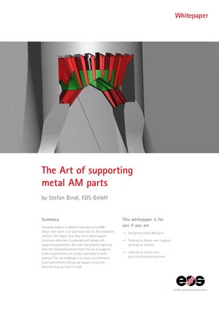
  • 1. Summary Seasoned experts in additive manufacturing (AM) design their parts in an optimized way for the production method. This means, that they try to avoid support structures wherever it is possible and choose self- supporting geometries. But even the greatest ingenuity does not necessarily prevent from the use of supports. Some characteristics are simply impossible to build without. The real challenge is to create such elements smart and efficient. Designing support structures therefore is an art form in itself. The Art of supporting metal AM parts by Stefan Bindl, EOS GmbH This whitepaper is for you if you are →→ Designing metal AM parts →→ Seeking to design your support generation smarter →→ Looking to reduce your post-build processing time Whitepaper
  • 2. 2 Nowadays building metal parts by additive manufacturing requires a tremendous amount of support structures as the designs in most cases do not really address AM requirements. But even with specific designs for additive manufacturing some support structures may be necessary. Besides the boundary conditions, there are always the same requirements for suitable support structures: →→ Easy to remove →→ Strong enough to hold the part →→ Short build time →→ Material saving The Art of supporting metal AM parts Indeed every AM engineer who is dealing with this topic for a while knows about those. The only question arising is, how can we get the conflict of aims solved or at least find a suitable trade off? By using a demo part we want to give an idea on the “Art of supporting metal AM parts”. Let us start with the part first: This is a design study for a combustion chamber used in aircraft or helicopter gas turbine engines. The entire design was dedicated to the manufacturing method of AM, requiring virtually no overhangs to be supported or any other geometries that would feature any kind of support structures (see figure 1). So far so good. Design Study of an annular combustion chamber with differently shaped air inlets
  • 3. 3 Integration of ­attachment points Now as there was no opportunity to integrate the adjacent module, the turbine casing, into this part some attachment points had to be integrated. In an ideal world we would have a closer look on the nozzle guide vane to see how we can make use of additive manufacturing to combine both components or at least create an advanced interface. For this case, let’s assume for some reasons we have to stick to the already predefined attachment points of the turbine casing. Augmenting those, the combustion chamber could look like this. Design optimization to reduce ­supported ­surfaces Now it is relatively obvious, that these overhangs will need support structures and as they are very high above the building platform they need to be connected to the part. What could be done from the design was to modify the down facing surface a bit. As this surface is going to be rough even if using support structures we can make the best out of it and use the surface to ensure the bolts and nuts will not loosen during usage. In this case, some sharp ripplets have been introduced to realize the functional surface. In addition the support structures can be reduced as the exposed area per layer is reduced as well. Figure 3 illustrates the new design. Annular combustor with mounting devices to attach to the turbine casing Detailed view of the attachment points and the ripped downward facing area
  • 4. 4 From obvious to smart supports The most important question still remains open – how can we realize the support structure in a smart way? As can be derived from the design, the removal of the support structures within this small gap underneath the attachment points would require high efforts. In order to solve this problem an additional part was created, with the purpose of holding the supports and make it possible to remove them. This additional block features two bottom surfaces to be connected to the part and the top surface to be the basis for the support holding the attachment geometry. The block itself is designed to be self-supported and does not require any additional supports. Speaking about the smart way of building supports this block has one key feature. Inside it comprises an internal hexagon to be able to twist it after the built breaking the supports and getting them out. In addition to this functional integrated support assistant some conventional support structures have to be designed. Therefore one of the various supporting tools can be utilized. In this case Materialise Magics was used to create block supports. The support in between the combustor and the support block was designed in a way that it just holds the ripplets in place and conducts the heat. At this location no strong support and no really sophisticated connection to the part is needed as the shackle grows out of the surrounding walls of the burner. On the other hand the support beneath the support block needs to hold the block and withstand the impacting recoating forces during the build. Having a circular combustion chamber there are always some supports and support blocks angled in a disadvantageous position. Hence, the two supports, one on each side, feature a finer hatch distance compared to the upper support in order to make them stronger. Both block supports, the upper and the lower, feature teeth to the combustion chamber and closed walls and border walls without teeth to the support block. This is because of the later removal. Due to the weaker connection with the combustion chamber it is supposed to break there and not at the support block. As the entire supports will be broken by twisting them an increased teeth height contributes positively to the ease of removal. CAD created support block featuring self-supporting geometry (left) and hexagon hole (right)
  • 5. 5 Setting up the exposure is also a crucial step within this support generation. The kind of exposure assigned has a significant influence on the performance of the support and the buildability of the part in total. The following modifications have been made to successfully build the part and being able to remove the support structures afterwards. The upper support, as it can be weak, was set to a lower energy level to reduce the connected surface on the one hand and to make the walls more fragile on the other. The two lower supports have been built with the standard EOS_External_Support parameter The support block itself is waste material and therefore does not need to feature highest material properties. Therefore, the hatch distance was increased to speed up the process by reducing laser tracks and in addition the contours have been disabled. This has a positive effect on build time as well as the recoater contact is decreased because of the reduced energy introduction at the parts borders. In order to identify a suitable configuration of support geometry and process parameters it might be useful to build some test parts to evaluate different settings. In this case this was done on an EOS M 290 (see figure 7) and the results have been transferred to the EOS M 400 on which the combustion chamber was finally built (fig. 8). Additional support block featuring all support structures for the build Getting the support out by an Allen key
  • 6. Dr Stefan Bindl EOS In 2005, Stefan Bindl graduated in aerospace engineering at the Technical University of Munich. He complemented his engineering studies with practical experience at several different research facilities focused on propulsion systems. He undertook his diploma thesis on at the Institute of Jet Propulsion at the University of the German Federal Armed Forces in Munich, and continued working there until 2015, first as research assistant until his doctorate in 2010, then as team leader for the engine test facility and finally, Stefan Bindl was professor for aircraft engine dynamics. In 2015 he joined EOS. Contact: stefan.bindl@eos.info EOS GmbH Electro Optical Systems Corporate Headquarters Robert-Stirling-Ring 1 82152 Krailling/Munich Germany Phone +49 89 893 36-0 Fax +49 89 893 36-285 www.eos.info Status 02/2017. Technical data subject to change without notice. EOS is certified according to ISO 9001. EOS® and e-Manufaturing® are registered trademarks of EOS GmbH in some countries. For more information visit www.eos.info/trademarks. Share your ideas, remarks and comments with us! email@eos.info