SlideShare a Scribd company logo
1 of 15
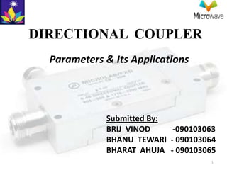
DIRECTIONAL COUPLER
  Parameters & Its Applications


             Submitted By:
             BRIJ VINOD    -090103063
             BHANU TEWARI - 090103064
             BHARAT AHUJA - 090103065
                                    1
DIRECTIONAL COUPLER
• A directional coupler is a passive device which
  couples part of the transmission power by a known
  amount out through another port, often by using
  two transmission lines set close enough together
  such that energy passing through one is coupled to
  the other.

• The device has four ports:
  input, transmitted, coupled, and isolated. The term
  "main line" refers to the section between ports 1 and
  2.

• Common properties desired for all directional
  couplers are wide operational bandwidth, high
  directivity, and a good impedance match at all ports
  when the other ports are terminated in matched          2
3
PARAMETERS:
Coupling factor:
• The coupling factor is defined as:


where P1 is the input power at port 1 and P3
 is the output power from the coupled
 port.

• The coupling factor represents the
  primary property of a directional coupler.

• Coupling is not constant, but varies with
  frequency.                                   4
continued……
• Directional couplers are specified in terms of the
  coupling accuracy at the frequency band center. For
  example, a 10 dB coupling ± 0.5 dB means that the
  directional coupler can have 9.5 dB to 10.5 dB
  coupling at the frequency band center.

• The accuracy is due to dimensional tolerances that
  can be held for the spacing of the two coupled lines.

• Another coupling specification is frequency
  sensitivity. A larger frequency sensitivity will allow a
  larger frequency band of operation.
                                                             5
Loss
The main line insertion loss from port 1 to port 2
  (P1 – P2) is:
• Insertion loss:

• Part of this loss is due to some power going to
  the coupled port and is called coupling loss and
  is given by-
• Coupling loss:


                                                     6
continued……
• The actual directional coupler loss will be a combination
  of coupling loss, dielectric loss, conductor loss, and VSWR
  loss. Depending on the frequency range, coupling loss
  becomes less significant above 15 dB coupling where the
  other losses constitute the majority of the total loss.


  A graph of the theoretical insertion loss (dB) vs coupling (dB) for   7
  adissipationless coupler is shown in Figure 2.
Isolation
• Isolation of a directional coupler can be defined as the
  difference in signal levels in dB between the input port
  and the isolated port when the two other ports are
  terminated by matched loads.

• Isolation:

• It can also be defined between the two output ports. In
  this case, one of the output ports is used as the input;
  the other is considered the output port while the other
  two ports (input and isolated) are terminated by
  matched loads.
                                                       8
continued……


• Consequently:

• The isolation between the input and the isolated ports
  may be different from the isolation between the two
  output ports.

• For example, the isolation between ports 1 and 4 can
  be 30 dB while the isolation between ports 2 and 3 can
  be a different value such as 25 dB. Isolation can be
  estimated from the coupling plus return loss.      9
Directivity
• Directivity is directly related to isolation.
  It is defined as:


 where: P3 is the output power from the
 coupled port and P4 is the power output
 from the isolated port.

• The directivity should be as high as
  possible. The directivity is very high at
  the design frequency and is a more
  sensitive function of frequency because it
  depends on the cancellation of two wave
                                          10
  components.
continued……

• Waveguide directional couplers will have the
  best directivity.

• Directivity is not directly measurable, and is
  calculated from the difference of the isolation
  and coupling measurements as:


                                                    11
APPLICATIONS
• Monitoring / Power
  measurements
  The coupled output from
  the directional coupler
  can be used to monitor
  frequency and power
  level on the signal
  without interrupting the
  main power flow in the
  system.                    12
continued……


• Frequency measurements
• Signal levelling
• Reflection coefficient
  measurements
• Signal sampling
• Signal injection
• Measure incident and reflected
  power to determine VSWR
                            13
continued……


• Making use of isolation-
  If isolation is
  high, directional couplers
  are good for combining
  signals to feed a single
  line to a receiver.


                                             14
15

More Related Content

What's hot

Rf and microwave components and devices
Rf and microwave components and devicesRf and microwave components and devices
Rf and microwave components and devicesShankar Gangaju
 
Digital modulation techniques...
Digital modulation techniques...Digital modulation techniques...
Digital modulation techniques...Nidhi Baranwal
 
Network analysis of rf and microwave circuits
Network analysis of rf and microwave circuitsNetwork analysis of rf and microwave circuits
Network analysis of rf and microwave circuitsShankar Gangaju
 
Unit 3- OPTICAL SOURCES AND DETECTORS
Unit 3- OPTICAL SOURCES AND DETECTORS Unit 3- OPTICAL SOURCES AND DETECTORS
Unit 3- OPTICAL SOURCES AND DETECTORS tamil arasan
 
Antennas wave and propagation
 Antennas wave and propagation Antennas wave and propagation
Antennas wave and propagationIsha Negi
 
Microwave hybrid circuits
Microwave hybrid circuitsMicrowave hybrid circuits
Microwave hybrid circuitsVikram Bansal
 
Concept of Diversity & Fading (wireless communication)
Concept of Diversity & Fading (wireless communication)Concept of Diversity & Fading (wireless communication)
Concept of Diversity & Fading (wireless communication)Omkar Rane
 
Space wave propagation ppt
Space wave propagation pptSpace wave propagation ppt
Space wave propagation pptdhanesh1994
 
Types of transmission lines
Types of transmission linesTypes of transmission lines
Types of transmission linesSelf-employed
 
Microwave Engineering Lecture Notes
Microwave Engineering Lecture NotesMicrowave Engineering Lecture Notes
Microwave Engineering Lecture NotesFellowBuddy.com
 
NYQUIST CRITERION FOR ZERO ISI
NYQUIST CRITERION FOR ZERO ISINYQUIST CRITERION FOR ZERO ISI
NYQUIST CRITERION FOR ZERO ISIFAIZAN SHAFI
 
cellular concepts in wireless communication
cellular concepts in wireless communicationcellular concepts in wireless communication
cellular concepts in wireless communicationasadkhan1327
 
Phase shifter presentation
Phase shifter presentationPhase shifter presentation
Phase shifter presentationalbertvinay
 
Ec 2401 wireless communication unit 2
Ec 2401 wireless communication   unit 2Ec 2401 wireless communication   unit 2
Ec 2401 wireless communication unit 2JAIGANESH SEKAR
 

What's hot (20)

Microwave measurement
Microwave measurementMicrowave measurement
Microwave measurement
 
Rf and microwave components and devices
Rf and microwave components and devicesRf and microwave components and devices
Rf and microwave components and devices
 
Antenna (2)
Antenna (2)Antenna (2)
Antenna (2)
 
Microwave Phase shifter
Microwave Phase shifterMicrowave Phase shifter
Microwave Phase shifter
 
Digital modulation techniques...
Digital modulation techniques...Digital modulation techniques...
Digital modulation techniques...
 
Network analysis of rf and microwave circuits
Network analysis of rf and microwave circuitsNetwork analysis of rf and microwave circuits
Network analysis of rf and microwave circuits
 
Unit 3- OPTICAL SOURCES AND DETECTORS
Unit 3- OPTICAL SOURCES AND DETECTORS Unit 3- OPTICAL SOURCES AND DETECTORS
Unit 3- OPTICAL SOURCES AND DETECTORS
 
Antennas wave and propagation
 Antennas wave and propagation Antennas wave and propagation
Antennas wave and propagation
 
Antenna Basics
Antenna BasicsAntenna Basics
Antenna Basics
 
Microwave hybrid circuits
Microwave hybrid circuitsMicrowave hybrid circuits
Microwave hybrid circuits
 
Concept of Diversity & Fading (wireless communication)
Concept of Diversity & Fading (wireless communication)Concept of Diversity & Fading (wireless communication)
Concept of Diversity & Fading (wireless communication)
 
Space wave propagation ppt
Space wave propagation pptSpace wave propagation ppt
Space wave propagation ppt
 
Line coding
Line codingLine coding
Line coding
 
Types of transmission lines
Types of transmission linesTypes of transmission lines
Types of transmission lines
 
Microwave Engineering Lecture Notes
Microwave Engineering Lecture NotesMicrowave Engineering Lecture Notes
Microwave Engineering Lecture Notes
 
NYQUIST CRITERION FOR ZERO ISI
NYQUIST CRITERION FOR ZERO ISINYQUIST CRITERION FOR ZERO ISI
NYQUIST CRITERION FOR ZERO ISI
 
Power Divider
Power DividerPower Divider
Power Divider
 
cellular concepts in wireless communication
cellular concepts in wireless communicationcellular concepts in wireless communication
cellular concepts in wireless communication
 
Phase shifter presentation
Phase shifter presentationPhase shifter presentation
Phase shifter presentation
 
Ec 2401 wireless communication unit 2
Ec 2401 wireless communication   unit 2Ec 2401 wireless communication   unit 2
Ec 2401 wireless communication unit 2
 

Viewers also liked

RF circuit design using ADS
RF circuit design using ADSRF circuit design using ADS
RF circuit design using ADSankit_master
 
Waveguide presentation
Waveguide presentationWaveguide presentation
Waveguide presentationSyed Umar
 
Seminar on ''Magic tee" by kazi md saidur rahaman
Seminar on ''Magic tee"  by kazi md saidur rahamanSeminar on ''Magic tee"  by kazi md saidur rahaman
Seminar on ''Magic tee" by kazi md saidur rahamanKazi Md Saidur Rahaman
 
Lecture notes microwaves
Lecture notes   microwavesLecture notes   microwaves
Lecture notes microwavesSarah Krystelle
 
Microwaves presentation
Microwaves presentationMicrowaves presentation
Microwaves presentationfascinating
 
Microwave waveguides 1st 1
Microwave waveguides 1st 1Microwave waveguides 1st 1
Microwave waveguides 1st 1HIMANSHU DIWAKAR
 
219272664 s-parameters
219272664 s-parameters219272664 s-parameters
219272664 s-parametersManish Arora
 
Rectangular waveguides
Rectangular waveguidesRectangular waveguides
Rectangular waveguideskhan yaseen
 
Waveguide for Microwave Communication
Waveguide for Microwave CommunicationWaveguide for Microwave Communication
Waveguide for Microwave CommunicationMd. Shoheluzzaman
 
Microwaves Applications
Microwaves ApplicationsMicrowaves Applications
Microwaves ApplicationsUmer Shehzad
 
Equal Split Wilkinson Power Divider - Project Presentation
Equal Split Wilkinson Power Divider - Project PresentationEqual Split Wilkinson Power Divider - Project Presentation
Equal Split Wilkinson Power Divider - Project PresentationBhanwar Singh Meena
 
Ec 55 transmission lines and waveguides b
Ec 55 transmission lines and waveguides bEc 55 transmission lines and waveguides b
Ec 55 transmission lines and waveguides barularumugam09
 

Viewers also liked (20)

Wave guide tees
Wave guide teesWave guide tees
Wave guide tees
 
180 hybrid-coupler
180 hybrid-coupler180 hybrid-coupler
180 hybrid-coupler
 
RF circuit design using ADS
RF circuit design using ADSRF circuit design using ADS
RF circuit design using ADS
 
Microwave devices
Microwave devicesMicrowave devices
Microwave devices
 
Waveguide presentation
Waveguide presentationWaveguide presentation
Waveguide presentation
 
Seminar on ''Magic tee" by kazi md saidur rahaman
Seminar on ''Magic tee"  by kazi md saidur rahamanSeminar on ''Magic tee"  by kazi md saidur rahaman
Seminar on ''Magic tee" by kazi md saidur rahaman
 
Lecture notes microwaves
Lecture notes   microwavesLecture notes   microwaves
Lecture notes microwaves
 
Waveguides
WaveguidesWaveguides
Waveguides
 
Microwaves presentation
Microwaves presentationMicrowaves presentation
Microwaves presentation
 
Microwave waveguides 1st 1
Microwave waveguides 1st 1Microwave waveguides 1st 1
Microwave waveguides 1st 1
 
Unit iii mirowave passive components
Unit iii mirowave passive componentsUnit iii mirowave passive components
Unit iii mirowave passive components
 
219272664 s-parameters
219272664 s-parameters219272664 s-parameters
219272664 s-parameters
 
Rectangular waveguides
Rectangular waveguidesRectangular waveguides
Rectangular waveguides
 
Mwr ppt priyanka
Mwr ppt priyankaMwr ppt priyanka
Mwr ppt priyanka
 
Waveguide for Microwave Communication
Waveguide for Microwave CommunicationWaveguide for Microwave Communication
Waveguide for Microwave Communication
 
Microwaves Applications
Microwaves ApplicationsMicrowaves Applications
Microwaves Applications
 
Microwave
Microwave Microwave
Microwave
 
Ferrite phase shifter
Ferrite phase shifterFerrite phase shifter
Ferrite phase shifter
 
Equal Split Wilkinson Power Divider - Project Presentation
Equal Split Wilkinson Power Divider - Project PresentationEqual Split Wilkinson Power Divider - Project Presentation
Equal Split Wilkinson Power Divider - Project Presentation
 
Ec 55 transmission lines and waveguides b
Ec 55 transmission lines and waveguides bEc 55 transmission lines and waveguides b
Ec 55 transmission lines and waveguides b
 

Similar to Microwave- directional coupler paramets & applications

power dividers and directional couplers.pptx
power dividers and directional couplers.pptxpower dividers and directional couplers.pptx
power dividers and directional couplers.pptxanitha862251
 
BT21ECE101A Wilkinson power divider,.pptx
BT21ECE101A Wilkinson power divider,.pptxBT21ECE101A Wilkinson power divider,.pptx
BT21ECE101A Wilkinson power divider,.pptxS075AbhishekDeshmukh
 
BT21ECE102RadioFrequencyand microwaves.pptx
BT21ECE102RadioFrequencyand microwaves.pptxBT21ECE102RadioFrequencyand microwaves.pptx
BT21ECE102RadioFrequencyand microwaves.pptxS075AbhishekDeshmukh
 
18 FM_Demodulators-Foster_Seeley_and_Ratio_Detector.pdf
18 FM_Demodulators-Foster_Seeley_and_Ratio_Detector.pdf18 FM_Demodulators-Foster_Seeley_and_Ratio_Detector.pdf
18 FM_Demodulators-Foster_Seeley_and_Ratio_Detector.pdfMohamedshabana38
 
Optical network components lecture 02
Optical network components lecture 02Optical network components lecture 02
Optical network components lecture 02Umesh Pinjarkar
 
Special transformers
Special transformersSpecial transformers
Special transformersPreet_patel
 
Detection of fault location in underground cable using arduino
Detection of fault location in underground cable using arduinoDetection of fault location in underground cable using arduino
Detection of fault location in underground cable using arduinoChirag Lakhani
 
Ch14 transmission line. Class 11 cbse ..
Ch14 transmission line. Class 11 cbse ..Ch14 transmission line. Class 11 cbse ..
Ch14 transmission line. Class 11 cbse ..MukeshSharma132089
 
9TH WEBINAR ON PASSIVE MICROWAVE DEVICES.pptx
9TH WEBINAR ON PASSIVE MICROWAVE DEVICES.pptx9TH WEBINAR ON PASSIVE MICROWAVE DEVICES.pptx
9TH WEBINAR ON PASSIVE MICROWAVE DEVICES.pptxdbharathidhasan
 
Power_Line_Carrier_Communication.pptx
Power_Line_Carrier_Communication.pptxPower_Line_Carrier_Communication.pptx
Power_Line_Carrier_Communication.pptxVara Prasad
 
Transceiver design
Transceiver designTransceiver design
Transceiver designChetan Soni
 
Data converter fundamentals
Data converter fundamentalsData converter fundamentals
Data converter fundamentalsAbhishek Kadam
 
Analog Electronics - Basics - Part-1
Analog Electronics - Basics - Part-1Analog Electronics - Basics - Part-1
Analog Electronics - Basics - Part-1MEENAKSHISUNDARAVELS
 
Fiber Optics Lab Experiments (EDWDM KIT,EDCOM KIT, EDLASE KIT, EDAMP KIT, L...
Fiber Optics Lab  Experiments (EDWDM KIT,EDCOM KIT, EDLASE KIT, EDAMP KIT,  L...Fiber Optics Lab  Experiments (EDWDM KIT,EDCOM KIT, EDLASE KIT, EDAMP KIT,  L...
Fiber Optics Lab Experiments (EDWDM KIT,EDCOM KIT, EDLASE KIT, EDAMP KIT, L...megha agrawal
 
Wdm passive components
Wdm passive componentsWdm passive components
Wdm passive componentsArun K Mohan
 
Planar Passive Components and Filters (MMICs)
Planar Passive Components and Filters (MMICs)Planar Passive Components and Filters (MMICs)
Planar Passive Components and Filters (MMICs)FAIZAN AHMAD
 
High Performance Printed Circuit Boards - Lecture #3
High Performance Printed Circuit Boards - Lecture #3High Performance Printed Circuit Boards - Lecture #3
High Performance Printed Circuit Boards - Lecture #3Samsung Electro-Mechanics
 

Similar to Microwave- directional coupler paramets & applications (20)

power dividers and directional couplers.pptx
power dividers and directional couplers.pptxpower dividers and directional couplers.pptx
power dividers and directional couplers.pptx
 
BT21ECE101A Wilkinson power divider,.pptx
BT21ECE101A Wilkinson power divider,.pptxBT21ECE101A Wilkinson power divider,.pptx
BT21ECE101A Wilkinson power divider,.pptx
 
BT21ECE102RadioFrequencyand microwaves.pptx
BT21ECE102RadioFrequencyand microwaves.pptxBT21ECE102RadioFrequencyand microwaves.pptx
BT21ECE102RadioFrequencyand microwaves.pptx
 
UNIT_5 PPT-MBM.pptx
UNIT_5 PPT-MBM.pptxUNIT_5 PPT-MBM.pptx
UNIT_5 PPT-MBM.pptx
 
18 FM_Demodulators-Foster_Seeley_and_Ratio_Detector.pdf
18 FM_Demodulators-Foster_Seeley_and_Ratio_Detector.pdf18 FM_Demodulators-Foster_Seeley_and_Ratio_Detector.pdf
18 FM_Demodulators-Foster_Seeley_and_Ratio_Detector.pdf
 
Optical network components lecture 02
Optical network components lecture 02Optical network components lecture 02
Optical network components lecture 02
 
Special transformers
Special transformersSpecial transformers
Special transformers
 
Detection of fault location in underground cable using arduino
Detection of fault location in underground cable using arduinoDetection of fault location in underground cable using arduino
Detection of fault location in underground cable using arduino
 
Ch14 transmission line. Class 11 cbse ..
Ch14 transmission line. Class 11 cbse ..Ch14 transmission line. Class 11 cbse ..
Ch14 transmission line. Class 11 cbse ..
 
Mod5part1
Mod5part1Mod5part1
Mod5part1
 
9TH WEBINAR ON PASSIVE MICROWAVE DEVICES.pptx
9TH WEBINAR ON PASSIVE MICROWAVE DEVICES.pptx9TH WEBINAR ON PASSIVE MICROWAVE DEVICES.pptx
9TH WEBINAR ON PASSIVE MICROWAVE DEVICES.pptx
 
Power_Line_Carrier_Communication.pptx
Power_Line_Carrier_Communication.pptxPower_Line_Carrier_Communication.pptx
Power_Line_Carrier_Communication.pptx
 
Transceiver design
Transceiver designTransceiver design
Transceiver design
 
Data converter fundamentals
Data converter fundamentalsData converter fundamentals
Data converter fundamentals
 
Analog Electronics - Basics - Part-1
Analog Electronics - Basics - Part-1Analog Electronics - Basics - Part-1
Analog Electronics - Basics - Part-1
 
Fiber Optics Lab Experiments (EDWDM KIT,EDCOM KIT, EDLASE KIT, EDAMP KIT, L...
Fiber Optics Lab  Experiments (EDWDM KIT,EDCOM KIT, EDLASE KIT, EDAMP KIT,  L...Fiber Optics Lab  Experiments (EDWDM KIT,EDCOM KIT, EDLASE KIT, EDAMP KIT,  L...
Fiber Optics Lab Experiments (EDWDM KIT,EDCOM KIT, EDLASE KIT, EDAMP KIT, L...
 
Unit 3
Unit 3Unit 3
Unit 3
 
Wdm passive components
Wdm passive componentsWdm passive components
Wdm passive components
 
Planar Passive Components and Filters (MMICs)
Planar Passive Components and Filters (MMICs)Planar Passive Components and Filters (MMICs)
Planar Passive Components and Filters (MMICs)
 
High Performance Printed Circuit Boards - Lecture #3
High Performance Printed Circuit Boards - Lecture #3High Performance Printed Circuit Boards - Lecture #3
High Performance Printed Circuit Boards - Lecture #3
 

Recently uploaded

Interactive Powerpoint_How to Master effective communication
Interactive Powerpoint_How to Master effective communicationInteractive Powerpoint_How to Master effective communication
Interactive Powerpoint_How to Master effective communicationnomboosow
 
Russian Call Girls in Andheri Airport Mumbai WhatsApp 9167673311 💞 Full Nigh...
Russian Call Girls in Andheri Airport Mumbai WhatsApp  9167673311 💞 Full Nigh...Russian Call Girls in Andheri Airport Mumbai WhatsApp  9167673311 💞 Full Nigh...
Russian Call Girls in Andheri Airport Mumbai WhatsApp 9167673311 💞 Full Nigh...Pooja Nehwal
 
Software Engineering Methodologies (overview)
Software Engineering Methodologies (overview)Software Engineering Methodologies (overview)
Software Engineering Methodologies (overview)eniolaolutunde
 
The basics of sentences session 2pptx copy.pptx
The basics of sentences session 2pptx copy.pptxThe basics of sentences session 2pptx copy.pptx
The basics of sentences session 2pptx copy.pptxheathfieldcps1
 
Z Score,T Score, Percential Rank and Box Plot Graph
Z Score,T Score, Percential Rank and Box Plot GraphZ Score,T Score, Percential Rank and Box Plot Graph
Z Score,T Score, Percential Rank and Box Plot GraphThiyagu K
 
SOCIAL AND HISTORICAL CONTEXT - LFTVD.pptx
SOCIAL AND HISTORICAL CONTEXT - LFTVD.pptxSOCIAL AND HISTORICAL CONTEXT - LFTVD.pptx
SOCIAL AND HISTORICAL CONTEXT - LFTVD.pptxiammrhaywood
 
Beyond the EU: DORA and NIS 2 Directive's Global Impact
Beyond the EU: DORA and NIS 2 Directive's Global ImpactBeyond the EU: DORA and NIS 2 Directive's Global Impact
Beyond the EU: DORA and NIS 2 Directive's Global ImpactPECB
 
Measures of Dispersion and Variability: Range, QD, AD and SD
Measures of Dispersion and Variability: Range, QD, AD and SDMeasures of Dispersion and Variability: Range, QD, AD and SD
Measures of Dispersion and Variability: Range, QD, AD and SDThiyagu K
 
Accessible design: Minimum effort, maximum impact
Accessible design: Minimum effort, maximum impactAccessible design: Minimum effort, maximum impact
Accessible design: Minimum effort, maximum impactdawncurless
 
APM Welcome, APM North West Network Conference, Synergies Across Sectors
APM Welcome, APM North West Network Conference, Synergies Across SectorsAPM Welcome, APM North West Network Conference, Synergies Across Sectors
APM Welcome, APM North West Network Conference, Synergies Across SectorsAssociation for Project Management
 
Introduction to Nonprofit Accounting: The Basics
Introduction to Nonprofit Accounting: The BasicsIntroduction to Nonprofit Accounting: The Basics
Introduction to Nonprofit Accounting: The BasicsTechSoup
 
BAG TECHNIQUE Bag technique-a tool making use of public health bag through wh...
BAG TECHNIQUE Bag technique-a tool making use of public health bag through wh...BAG TECHNIQUE Bag technique-a tool making use of public health bag through wh...
BAG TECHNIQUE Bag technique-a tool making use of public health bag through wh...Sapna Thakur
 
JAPAN: ORGANISATION OF PMDA, PHARMACEUTICAL LAWS & REGULATIONS, TYPES OF REGI...
JAPAN: ORGANISATION OF PMDA, PHARMACEUTICAL LAWS & REGULATIONS, TYPES OF REGI...JAPAN: ORGANISATION OF PMDA, PHARMACEUTICAL LAWS & REGULATIONS, TYPES OF REGI...
JAPAN: ORGANISATION OF PMDA, PHARMACEUTICAL LAWS & REGULATIONS, TYPES OF REGI...anjaliyadav012327
 
The byproduct of sericulture in different industries.pptx
The byproduct of sericulture in different industries.pptxThe byproduct of sericulture in different industries.pptx
The byproduct of sericulture in different industries.pptxShobhayan Kirtania
 
Paris 2024 Olympic Geographies - an activity
Paris 2024 Olympic Geographies - an activityParis 2024 Olympic Geographies - an activity
Paris 2024 Olympic Geographies - an activityGeoBlogs
 
Sports & Fitness Value Added Course FY..
Sports & Fitness Value Added Course FY..Sports & Fitness Value Added Course FY..
Sports & Fitness Value Added Course FY..Disha Kariya
 
Student login on Anyboli platform.helpin
Student login on Anyboli platform.helpinStudent login on Anyboli platform.helpin
Student login on Anyboli platform.helpinRaunakKeshri1
 
Organic Name Reactions for the students and aspirants of Chemistry12th.pptx
Organic Name Reactions  for the students and aspirants of Chemistry12th.pptxOrganic Name Reactions  for the students and aspirants of Chemistry12th.pptx
Organic Name Reactions for the students and aspirants of Chemistry12th.pptxVS Mahajan Coaching Centre
 
1029-Danh muc Sach Giao Khoa khoi 6.pdf
1029-Danh muc Sach Giao Khoa khoi  6.pdf1029-Danh muc Sach Giao Khoa khoi  6.pdf
1029-Danh muc Sach Giao Khoa khoi 6.pdfQucHHunhnh
 
Grant Readiness 101 TechSoup and Remy Consulting
Grant Readiness 101 TechSoup and Remy ConsultingGrant Readiness 101 TechSoup and Remy Consulting
Grant Readiness 101 TechSoup and Remy ConsultingTechSoup
 

Recently uploaded (20)

Interactive Powerpoint_How to Master effective communication
Interactive Powerpoint_How to Master effective communicationInteractive Powerpoint_How to Master effective communication
Interactive Powerpoint_How to Master effective communication
 
Russian Call Girls in Andheri Airport Mumbai WhatsApp 9167673311 💞 Full Nigh...
Russian Call Girls in Andheri Airport Mumbai WhatsApp  9167673311 💞 Full Nigh...Russian Call Girls in Andheri Airport Mumbai WhatsApp  9167673311 💞 Full Nigh...
Russian Call Girls in Andheri Airport Mumbai WhatsApp 9167673311 💞 Full Nigh...
 
Software Engineering Methodologies (overview)
Software Engineering Methodologies (overview)Software Engineering Methodologies (overview)
Software Engineering Methodologies (overview)
 
The basics of sentences session 2pptx copy.pptx
The basics of sentences session 2pptx copy.pptxThe basics of sentences session 2pptx copy.pptx
The basics of sentences session 2pptx copy.pptx
 
Z Score,T Score, Percential Rank and Box Plot Graph
Z Score,T Score, Percential Rank and Box Plot GraphZ Score,T Score, Percential Rank and Box Plot Graph
Z Score,T Score, Percential Rank and Box Plot Graph
 
SOCIAL AND HISTORICAL CONTEXT - LFTVD.pptx
SOCIAL AND HISTORICAL CONTEXT - LFTVD.pptxSOCIAL AND HISTORICAL CONTEXT - LFTVD.pptx
SOCIAL AND HISTORICAL CONTEXT - LFTVD.pptx
 
Beyond the EU: DORA and NIS 2 Directive's Global Impact
Beyond the EU: DORA and NIS 2 Directive's Global ImpactBeyond the EU: DORA and NIS 2 Directive's Global Impact
Beyond the EU: DORA and NIS 2 Directive's Global Impact
 
Measures of Dispersion and Variability: Range, QD, AD and SD
Measures of Dispersion and Variability: Range, QD, AD and SDMeasures of Dispersion and Variability: Range, QD, AD and SD
Measures of Dispersion and Variability: Range, QD, AD and SD
 
Accessible design: Minimum effort, maximum impact
Accessible design: Minimum effort, maximum impactAccessible design: Minimum effort, maximum impact
Accessible design: Minimum effort, maximum impact
 
APM Welcome, APM North West Network Conference, Synergies Across Sectors
APM Welcome, APM North West Network Conference, Synergies Across SectorsAPM Welcome, APM North West Network Conference, Synergies Across Sectors
APM Welcome, APM North West Network Conference, Synergies Across Sectors
 
Introduction to Nonprofit Accounting: The Basics
Introduction to Nonprofit Accounting: The BasicsIntroduction to Nonprofit Accounting: The Basics
Introduction to Nonprofit Accounting: The Basics
 
BAG TECHNIQUE Bag technique-a tool making use of public health bag through wh...
BAG TECHNIQUE Bag technique-a tool making use of public health bag through wh...BAG TECHNIQUE Bag technique-a tool making use of public health bag through wh...
BAG TECHNIQUE Bag technique-a tool making use of public health bag through wh...
 
JAPAN: ORGANISATION OF PMDA, PHARMACEUTICAL LAWS & REGULATIONS, TYPES OF REGI...
JAPAN: ORGANISATION OF PMDA, PHARMACEUTICAL LAWS & REGULATIONS, TYPES OF REGI...JAPAN: ORGANISATION OF PMDA, PHARMACEUTICAL LAWS & REGULATIONS, TYPES OF REGI...
JAPAN: ORGANISATION OF PMDA, PHARMACEUTICAL LAWS & REGULATIONS, TYPES OF REGI...
 
The byproduct of sericulture in different industries.pptx
The byproduct of sericulture in different industries.pptxThe byproduct of sericulture in different industries.pptx
The byproduct of sericulture in different industries.pptx
 
Paris 2024 Olympic Geographies - an activity
Paris 2024 Olympic Geographies - an activityParis 2024 Olympic Geographies - an activity
Paris 2024 Olympic Geographies - an activity
 
Sports & Fitness Value Added Course FY..
Sports & Fitness Value Added Course FY..Sports & Fitness Value Added Course FY..
Sports & Fitness Value Added Course FY..
 
Student login on Anyboli platform.helpin
Student login on Anyboli platform.helpinStudent login on Anyboli platform.helpin
Student login on Anyboli platform.helpin
 
Organic Name Reactions for the students and aspirants of Chemistry12th.pptx
Organic Name Reactions  for the students and aspirants of Chemistry12th.pptxOrganic Name Reactions  for the students and aspirants of Chemistry12th.pptx
Organic Name Reactions for the students and aspirants of Chemistry12th.pptx
 
1029-Danh muc Sach Giao Khoa khoi 6.pdf
1029-Danh muc Sach Giao Khoa khoi  6.pdf1029-Danh muc Sach Giao Khoa khoi  6.pdf
1029-Danh muc Sach Giao Khoa khoi 6.pdf
 
Grant Readiness 101 TechSoup and Remy Consulting
Grant Readiness 101 TechSoup and Remy ConsultingGrant Readiness 101 TechSoup and Remy Consulting
Grant Readiness 101 TechSoup and Remy Consulting
 

Microwave- directional coupler paramets & applications

  • 1. DIRECTIONAL COUPLER Parameters & Its Applications Submitted By: BRIJ VINOD -090103063 BHANU TEWARI - 090103064 BHARAT AHUJA - 090103065 1
  • 2. DIRECTIONAL COUPLER • A directional coupler is a passive device which couples part of the transmission power by a known amount out through another port, often by using two transmission lines set close enough together such that energy passing through one is coupled to the other. • The device has four ports: input, transmitted, coupled, and isolated. The term "main line" refers to the section between ports 1 and 2. • Common properties desired for all directional couplers are wide operational bandwidth, high directivity, and a good impedance match at all ports when the other ports are terminated in matched 2
  • 3. 3
  • 4. PARAMETERS: Coupling factor: • The coupling factor is defined as: where P1 is the input power at port 1 and P3 is the output power from the coupled port. • The coupling factor represents the primary property of a directional coupler. • Coupling is not constant, but varies with frequency. 4
  • 5. continued…… • Directional couplers are specified in terms of the coupling accuracy at the frequency band center. For example, a 10 dB coupling ± 0.5 dB means that the directional coupler can have 9.5 dB to 10.5 dB coupling at the frequency band center. • The accuracy is due to dimensional tolerances that can be held for the spacing of the two coupled lines. • Another coupling specification is frequency sensitivity. A larger frequency sensitivity will allow a larger frequency band of operation. 5
  • 6. Loss The main line insertion loss from port 1 to port 2 (P1 – P2) is: • Insertion loss: • Part of this loss is due to some power going to the coupled port and is called coupling loss and is given by- • Coupling loss: 6
  • 7. continued…… • The actual directional coupler loss will be a combination of coupling loss, dielectric loss, conductor loss, and VSWR loss. Depending on the frequency range, coupling loss becomes less significant above 15 dB coupling where the other losses constitute the majority of the total loss. A graph of the theoretical insertion loss (dB) vs coupling (dB) for 7 adissipationless coupler is shown in Figure 2.
  • 8. Isolation • Isolation of a directional coupler can be defined as the difference in signal levels in dB between the input port and the isolated port when the two other ports are terminated by matched loads. • Isolation: • It can also be defined between the two output ports. In this case, one of the output ports is used as the input; the other is considered the output port while the other two ports (input and isolated) are terminated by matched loads. 8
  • 9. continued…… • Consequently: • The isolation between the input and the isolated ports may be different from the isolation between the two output ports. • For example, the isolation between ports 1 and 4 can be 30 dB while the isolation between ports 2 and 3 can be a different value such as 25 dB. Isolation can be estimated from the coupling plus return loss. 9
  • 10. Directivity • Directivity is directly related to isolation. It is defined as: where: P3 is the output power from the coupled port and P4 is the power output from the isolated port. • The directivity should be as high as possible. The directivity is very high at the design frequency and is a more sensitive function of frequency because it depends on the cancellation of two wave 10 components.
  • 11. continued…… • Waveguide directional couplers will have the best directivity. • Directivity is not directly measurable, and is calculated from the difference of the isolation and coupling measurements as: 11
  • 12. APPLICATIONS • Monitoring / Power measurements The coupled output from the directional coupler can be used to monitor frequency and power level on the signal without interrupting the main power flow in the system. 12
  • 13. continued…… • Frequency measurements • Signal levelling • Reflection coefficient measurements • Signal sampling • Signal injection • Measure incident and reflected power to determine VSWR 13
  • 14. continued…… • Making use of isolation- If isolation is high, directional couplers are good for combining signals to feed a single line to a receiver. 14
  • 15. 15