
Recomendados
Mais conteúdo relacionado
Mais procurados
Mais procurados (20)
Semelhante a Novel Variable Stiffness Gripper Design Using Magnets
Semelhante a Novel Variable Stiffness Gripper Design Using Magnets (20)
Novel Variable Stiffness Gripper Design Using Magnets
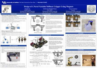
- 1. www.buffalo.edu Design of A Novel Variable Stiffness Gripper Using Magnets Hongfei Lin Graduate Student Mechanical and Aerospace Engineering State University of New York at Buffalo Amirhossein Hajiagha Memar Ph.D. Student Mechanical and Aerospace Engineering State University of New York at Buffalo Ehsan T Esfahani Professor Mechanical and Aerospace Engineering State University of New York at Buffalo INTRODUCTION OUR VSA MECHANISM EXPERIMENT AND SIMULATION In this experiment The stiffness was set to a low value to avoid damages to the fragile object. with a low stiffness. The end effector moved toward a table and one of the gripper fingers collided with the table. DESIGN AND MODELING Based on the experiment strategy, we also simulated this experiment in v-rep by creating the model for the gripper as well as the magnets and using Matlab to control the robotic arm and gripper. What is Variable Stiffness Actuator • If the stiffness of a compliant joint is adjustable, it is called a series elastic actuator (SEA) or a variable stiffness actuator (VSA). • In the VSA, an elastic elements such as a spring is used in series with a stiff actuator. The elastic element of VSA acts as a low-pass filter and absorbs the impact energy from or to the actuator. • VSA provides users with the intrinsic capabilities of bandwidth, impacts, and energy storage as well as a useful range of stiffness. Different Approach of VSA : • The stiffness varies by changing the elastic element preload. • The stiffness is altered by changing the transmission ratio between the load and the spring. • The stiffness is adjusted by changing the properties of elastic elements • Limitation:- • Safety is one of the most important factor in the robot interaction with unknown and dynamic environments and a robot needs to handle fragile or sharp objects as well as service robots during physical interaction with human. • High-efficiency is another important factor in industry. Based on VSA the gripper can handle more items with different kind of size, materials and shapes. Our Focus: • We want our gripper takes advantage of the magnetic force in repulsive configuration as the nonlinear elastic element. • To achieve variable stiffness function in a compact design and control the position and stiffness simultaneously by control two independent motor WHY IT’S IMPORTANT CONCLUSION • This project presented the design aspects of a novel variable stiffness gripper with two fingers. Magnetic springs in a repulsive configuration were used as the non-linear preload springs in an antagonistic springs with antagonistic actuators setup. • Two servo motors in position control mode were used to adjust the position and stiffness of the gripper simultaneously. • The proposed design provides the gripper with capability of force measurement individually for each finger. This property can provide the grasping controller with • higher capabilities and more stability in the case of uncertain grasping or collision with stiff objects. • An Experiment was conducted to show how the proposed variable stiffness gripper can improve grasping task in the context of safety and compliant motion. In this experiment the compliance of the gripper was investigated in a task where a robotic arm equipped with the designed gripper grasped a fragile object and an unexpected collision happened. • The results showed the effectiveness of the proposed mechanism for a two finger gripper.. One part of the future work is the gripper dynamic manipulate which means we would be able to use the gripper to throwing and catching a item like what human finger can do. The other part is have some experiment working with human-robot interaction to see how it will work when the gripper have some physical contact with human. FUTURE WORK In this project, permanent magnets were chosen as non-linear springs, since they can provide the system with not only a compact non-linear elasticity but also a noncontact force interaction between the actuators and the load Basically, in the absence of external forces, each finger tends to stay in the static equilibrium point which is at the middle of the two actuated magnets by neglecting the effect of gravity. This mechanism can be classified as antagonistic springs with antagonistic motors’ group because both the springs and the actuators are placed in an antagonistic setup. As a result, the position and stiffness of the fingers can be adjusted simultaneously, by controlling the positions of the actuated magnets. In this design, timing belt was used to transfer the rotational motion of actuators to translational movement of the magnets. Both sides of the belts were used to transfer actuator forces to the magnets because each pair of magnets need to move simultaneously. Each motor axis were passed through two pulleys; an active pulley fixated on the associated axis and one passive pulley maintaining the belt tension. The expression of the repulsive force between two cylindrical magnets with radius R, and height h can be well approximated by 𝐹𝑚 𝑠 = 𝜋𝑢0 𝑀2 𝑅4 4 1 𝑠2 + 1 (𝑠 + 2ℎ)2 − 2 (𝑠 + ℎ)2 (1) The distances between magnets can be calculated by 𝑙1 = 𝑑12 − 𝑊𝑚 − 𝑊𝑓 2 − ∆𝑥 𝑓 = 𝑥 𝑓 − 𝑥1 − 𝑊𝑚 + 𝑊𝑓 2 (2) 𝑙2 = 𝑑12 − 𝑊𝑚 − 𝑊𝑓 2 − ∆𝑥 𝑓 = 𝑥2 − 𝑥 𝑓 − 𝑊𝑚 + 𝑊𝑓 2 (3) Then the force can be calculated by 𝐹 𝑥1, 𝑥2, 𝑥 𝑓 = 𝐹 𝑚1 − 𝐹 𝑚2 = 𝐹𝑚 𝑙1 − 𝐹𝑚 𝑙2 (4) Mathematical expression of the stiffness for a given state can be derived using the chain rule 𝐾 𝑥1, 𝑥2, 𝑥 𝑓 = 𝑑𝐹𝑚 𝑑𝑥 𝑓 = 𝑑𝐹 𝑚1 𝑑𝑥 𝑓 − 𝑑𝐹 𝑚2 𝑑𝑥 𝑓 = 𝑑𝐹 𝑚1 𝑑𝑙1 𝑑𝑙1 𝑑𝑥 𝑓 − 𝑑𝐹 𝑚2 𝑑𝑙2 𝑑𝑙2 𝑑𝑥 𝑓 = 𝑑𝐹𝑚 𝑑𝑠 𝑙1 + 𝑑𝐹𝑚 𝑑𝑠 𝑙2 (5) Gripper Assembly Figure Gripper Force Model VSA Mechanism based on Magnet Gripper Attached with Robotic Arm Basic VSA Mechanism