
Recomendados
Mais conteúdo relacionado
Mais procurados
Destaque
Semelhante a 95ZJ_8R.PDF
Semelhante a 95ZJ_8R.PDF (11)
Mais de Åge Færestrand
Mais de Åge Færestrand (10)
Último
Último (8)
95ZJ_8R.PDF
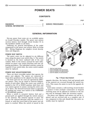
- 1. ZJ POWER SEATS 8R - 1 POWER SEATS CONTENTS page page DIAGNOSIS . . . . . . . . . . . . . . . . . . . . . . . . . . . . . 2 SERVICE PROCEDURES ................... 4 GENERAL INFORMATION . . . . . . . . . . . . . . . . . . 1 GENERAL INFORMATION Six-way power front seats are an available option on Grand Cherokee models. The power seat system receives battery feed through circuit breaker 25 in the fuseblock module at all times. Following are general descriptions of the major components in the power seat system. Refer to Group 8W - Wiring Diagrams for complete circuit descrip- tions and diagrams. POWER SEAT SWITCH The power seats can be adjusted in six different ways using the power seat switch (Fig. 1). The switch is located on the lower outboard side of the seat cushion. Refer to the owner’s manual for more infor- mation on power seat switch functions and seat ad- justing procedures. The individual switches cannot be repaired. If one switch fails, the entire switch module must be replaced. POWER SEAT ADJUSTER/MOTORS There are three reversible motors that operate the power seat adjuster. The motors are connected to worm-drive gearboxes in the adjuster by drive cables. Fig. 1 Power Seat Switch The front and rear of a seat are operated by differ- opposite direction, the battery feed and ground path ent motors. They can be raised or lowered indepen- to the motor(s) are reversed through the switch con- dently of each other. When the center seat switch is tacts. This causes the motor to run in the opposite di- pushed to the UP or DOWN position, both front and rection. rear motors operate in unison, moving the entire seat Each motor contains a self-resetting circuit breaker up or down. The forward-rearward motor is operated to protect it from overload. Consecutive or frequent by pushing the center seat switch to the FORWARD or REARWARD position. resetting must not be allowed to continue or the mo- When a switch is actuated, battery feed and a tors may be damaged. Make the necessary repairs. ground path are applied through the switch contacts The power seat adjuster and motors can not be re- to the motor(s). The motor(s) operate to move the paired, and are serviced only as a complete unit. If seat in the selected direction until the switch is re- any component in this unit should fail, the entire as- leased, or until the travel limit of the power seat ad- sembly must be replaced. juster is reached. When the switch is moved in the
- 2. 8R - 2 POWER SEATS ZJ DIAGNOSIS Before any testing is attempted the battery should (3) Check for continuity between black wire at be fully charged and all connections and pins cleaned switch connector and a good ground. There should be and tightened to ensure proper continuity and continuity. If OK, go to next step. If not OK, repair grounds. wiring to ground. With the dome lamp on, apply switch in direction (4) See diagnosis for Power Seat Switch. If switch of the failure. If the dome lamp dims, the seat may continuity checks OK, replace faulty motor/adjuster be jamming. Check for binding or obstructions. If the assembly. If switch continuity is not OK, replace dome lamp does not dim, then proceed with the fol- faulty switch. lowing electrical tests. POWER SEAT SWITCH POWER SEAT ADJUSTER/MOTORS To check the power seat switch, remove the switch Operate the power seat switch to move all three from its mounting position. Use an ohmmeter and seat motors. The seat should move in all directions. see Power Seat Switch Continuity chart. Determine If not OK, proceed as follows. If one or more motors if switch continuity is correct. If OK, see Power Seat operate, see diagnosis for Power Seat Switch. Adjuster/Motors diagnosis. If not OK, replace faulty (1) Check circuit breaker 25 in the fuseblock mod- ule. If OK, go to next step. If not OK, replace circuit switch assembly. breaker. (2) Remove switch mounting screws and check for battery voltage at red wire at switch connector. If OK, go to next step. If not OK, repair wiring to cir- cuit breaker. POWER SEAT SWITCH CONTINUITY (LEFT)
- 3. ZJ POWER SEATS 8R - 3 POWER SEAT SWITCH CONTINUITY (RIGHT)
- 4. 8R - 4 POWER SEATS ZJ SERVICE PROCEDURES POWER SEAT SWITCH REMOVE/INSTALL (1) Disconnect battery negative cable. (2) Remove screws securing outboard seat side trim. (3) Pull seat trim away from side of seat far enough to access multiple terminal block on switch. (4) Carefully release locking tabs securing multiple terminal block to switch and remove wiring from switch. (5) Remove screws securing switch to back of seat side trim and remove switch. (6) Reverse removal procedures to install. POWER SEAT ADJUSTER/MOTORS REMOVE/ INSTALL (1) Remove 2 screws and the rear track covers. (2) Remove 4 screws holding seat to floor pan (Fig. 2). Move adjuster as required for access. (3) Disconnect wiring harness power lead at car- pet. (4) Remove seat assembly from vehicle. (5) Disconnect seat switch wiring harness from mo- Fig. 2 Power Seat Remove - Typical tors. (6) Remove screws securing motor/adjuster assem- bly to seat frame (Fig. 3) and remove. (7) Reverse removal procedures to install. Tighten seat frame to motor/adjuster bolts and seat mounting bolts to 20 N⅐m (15 ft. lbs.). Fig. 3 Power Seat Motor/Adjuster - Typical