
Recomendados
Mais conteúdo relacionado
Mais procurados
Mais procurados (16)
Destaque
Semelhante a Living in Three Dimensions: Realities of 3D Modeling and Printing
Semelhante a Living in Three Dimensions: Realities of 3D Modeling and Printing (20)
Living in Three Dimensions: Realities of 3D Modeling and Printing
- 1. 1 Living in Three Dimensions: Realities of 3D Modeling and Printing Ethan Traveny Skaggs _Industrial Revolution of the 21st Century Software that allows designers to model in three dimensions has ignited a new-age industrial revolution, changing fabrication methods through a process formally called additive manufacturing. Using an industrial robot, additive manufacturing creates objects layer by layer.1 This method, in theory, permits any object or form that can be modeled in 3D to be printed in 3D. In today’s world, desktop printing is a reality; not only designers and engineers have the potential to rapid-prototype and create. Anything from guns to musical instruments has the ability to be printed. Open-source modeling, printing software packages are transforming the consistently developing veracity of at-home fabrication. Preparing geometric input for fabrication is similar to an architect’s section cut. There are specific, generated contours that divide an object modeled in 3D at a given interval, determined based on the desired resolution or the printer’s given capacity.2 Similar to sculpture, computer aided design (CAD) software packages allow the user to shape forms using sets of geometric or parametric tools. This paper will investigate the potential, risks, surprises, and overall practical differences of using two specific software packages, Rhinoceros 3D and SketchUp, and specific case studies of two projects that utilized their tools. _Rhinoceros 3D vs. SketchUp: an overview Rhinoceros 3D, typically shortened to “Rhino,” is a NURBS-based software. NURBS stands for non-uniform rational basis spline, a mathematical model for differential geometry that generates curves and surfaces based on precise control points and vectors. While these levels of sub and tertiary geometry are precise, NURBS-based software packages also offer flexibility in their ability to manipulate form and shape.3 Because all shapes are simplified to functions and algorithms, Rhino gives the operator complete control over adjustments to form. SketchUp, a startup company previously owned by tech giant Google, uses pure polygons to model in 3D. Forms are divided into mesh structures, which can simulate both straight and 1 Gibson, Ian. Additive Manufacturing Technologies: 3d Printing, Rapid Prototyping, and Direct Digital... Manufacturing. S.l.: Springer, 2014. Print. 2 "About 3D Printing." Revolution 3D Printers. http://revolution3dprinters.com/ Web. 03 Dec. 2014. 3 Cheng, Ron K. C. Inside Rhinoceros 5. 4th ed. Boston: Cengage Learning, 2014. Print. 4 ”Introducing SketchUp Pro 2013.” Trimble. Retrieved 4 December 2014.
- 2. 2 curved forms through rebuilding them as triangulated faces.4 As its name implies, SketchUp was founded to create concept, sketch-like models. Rhino, on the other hand, was designed for precision and control, both necessary for the prototyping and manufacturing of parts for assembly. Even though SketchUp does use control points, they are not the same as in Rhino; the operator is required to define explicitly the faces of an object and all its points. SketchUp restricts the general modeling capacity through denying most complex curvilinear forms, but its familiar “out of the box” sense and low learning curve attracts more general users than the industry-standard, somewhat intimidating package from the developers of Rhino. _Modeling Hermogenes Modeling Hermogenes is a recent project that involves extensive 3D modeling and fabrication. A group project involving fewer than ten key members, this seminar was designed to revive the ruins of the Temple of Artemis Leukophyrene (Artemision) at Magnesia in a revisualization effort in both two and three dimensions. This investigation involved modeling a series of specific components essential to our understanding of both the temple itself and the building process. With the majority of my peers modeling in the user-friendlier SketchUp, my experience with Rhino led to the desire to model using NURBS. Coming from a CAD-based background as an architecture student, and due to my specific responsibility of manufacturing the components, my comfort with the tools in Rhino eliminated the need for initial worries concerning the development of successful, printable parts that would be suitable for use in public exhibition. The choice of specific software among the varied pool of options is seemingly more important that it may seem, especially with the growing level of disposable technology available at our fingertips. With the amount of crossover in file types and smarter exporting capabilities, non-native software packages can translate models with a good amount of success. Because different software uses unique algorithms and offers different tools, many designers edit cross- platform. However, the benefit of conversion does not come without a price; it takes a mixture of skill, experience, and luck to anticipate how exporting a file (or changing the native program) will affect the model’s raw data. This data will ultimately be reread and translated again, in preparation for transcription by the 3d-printer.5 Understanding the full aptitude of one software 5 "How Stereolithography Works.” THRE3D.com. Retrieved 4 December 2014.
- 3. 3 package versus another reduces the risk of corruption or misrepresentation within a model and is generally recommended prior to the design’s conception. What happens when a designer cannot avoid using several software platforms? In the world of desktop fabrication, not everyone who wants to design and build will have industry- standard modeling software or the computer capacity to manage such a memory-absorbing process. In the case of Modeling Hermogenes, moving between Rhino and SketchUp proved to be informative in how to design smarter visually in Rhino but gave the impression that SketchUp lacked the ability to manipulate specific variables that directly affected the form – and success – of our models. The largest issue arose when detailing the ionic capital, the personally most difficult and challenging form I have ever modeled. Originally, Samuel Holzman, a graduate student at the University of Pennsylvania and one of the leaders within our seminar, labored over the ionic capital in SketchUp. Because the software is not specifically designed for precision fabrication, SketchUp does not natively support exporting to .STL (stereolithography), a file format that is standard for the majority of 3D printers and additive manufacturing robots. While the original ease and simplicity of SketchUp was enticing, it was now clear that we needed to use Rhino to export successfully to an .STL format. Rhino can write in thirty-eight unique file formats, SketchUp only ten (Figure I). Of these ten, only three (3DS, OBJ, and SketchUp) will export an entire field of 3D geometries – the rest are utilized primarily for two- dimensional line drawings and rastered images. The .3DS file format is tied specifically to Autodesk 3DS Max, a popular modeling software that has the ability to switch between NURBS and polygon modeling, similar to Rhino. An object file (.OBJ) is more elementary, mapping the geometries as pure polygons that can then be translated by countless programs. Because the capital was originally created as polygonal elements in SketchUp, .OBJ was the best choice for Figure I Rhinoceros 3D SketchUp Pro Writable file formats* Italicized formats are compatible with mapped, three-dimensional geometry. 3D PDF, 3DS, ACIS, ACIS SAT, ASCII, BITMAP, BMP, CATIA, DWG, DXF, FBX, IGES, IGS, AI, KMZ, Lightwave, LWO, OBJ, Parasolid, Parasolid XT, PDF, PLT, PNG, POV, Rhino, 3DM, SAT, SketchUp, SKP, STEP, STL, STP, VDA-FS, VRML, WMF, WRL 3DS, DWG, DXF, EPS, FBX, OBJ, PDF, SketchUp, VRML, WRL
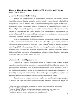
- 4. 4 minimizing the amount of potential corruption during the file’s exportation. When opening the .OBJ file for the first time in Rhino, the differences in SketchUp’s modeling processes were clear. Because SketchUp approximates curved forms using countless tangent polygons, details within ionic capital were unrecognizable (Figure II). An analysis through a simple Rhino command determined that the imported mesh object consisted of over 40,000 faces; this is incomprehensible for such a small model, which would ultimately only fit within a 3.75”x3.75”x2” rectangular prism when printed. If the model were built in Rhino, each element would be represented by a single, sculpted surface rather than an amalgamation of tangent faces. Additionally, there would be options for manipulating and molding the forms directly to alter the model’s overall appearance, in addition to the benefits of scaling, made easy by the mathematical operations that Rhino relies on. Regardless of the number of faces in the model, exporting to .STL was the only reason for importing the ionic capital into Rhino. The disjointed meshes were rebuilt to have fewer faces (polygonal elements), just under 25,000 prior to the final export. Bringing the file to the industrial, 3DSystems machine used in PennDesign’s Fabrication Lab quickly clued me in to the dangers of cross- platform model manipulation: the model appeared to have no thickness. All edges were considered “naked,” existing alone, completely unconnected with any other part of the model. Although some naked edges are easily read as hairline seams and automatically connected by most desktop machines, such as the MakerBot Replicator 2, this analysis revealed SketchUp’s inferiority in creating parts for fabrication. The amount of naked edges existing in this model meant that the printer would consider these elements as pseudoforms, printing nothing at all. My impression of the true definition of and reasoning behind the issues surrounding “naked edges” in three-dimensional fabrication led me to understand that the model had to be built existing as one, solid piece, as if it were a monolithic sculpture. Using the SketchUp model as just that, a concept for developing a functional part, I created the forms of the capital as Figure II: S. Holzman ionic capital exported from SketchUp as .OBJ, imported into Rhino as polygonal mesh. Faces and individual details obscured due to the countless polygons that comprise the overall form.
- 5. 5 polysurfaces in Rhino. Using the various Boolean operators, which are technical functions that deploy mathematical intervention between components in Rhino, I began a series of trial-and- error tests to create a workable file. The commands BooleanUnion and BooleanSplit allow two polysurfaces to be combined or subtracted respectively, while BooleanDifference subtracts the volume of one set of objects from the other and BooleanIntersection create a new solid from the junction of two other solids. Using these primary Boolean operators in combination ensured that each component of the model existed as a single piece, in hopes of avoiding the naked edges issue that SketchUp previously caused. After a painstaking process of manipulating Rhino’s extensive tools and commands, a capital was produced that read as one piece. This file was immediately exported as an .STL and printed. Eventually, a combination of silicone and epoxy allowed us to create molds for replicas of the fabricated pieces, reducing our cost of prototyping as we could now use a simple Plaster of Paris mixture rather than the time-consuming and costly process of additive manufacturing. Because .STL files contain a version of meshing (that is, the reduction of curved elements into polygons), why is SketchUp unable to produce printable model files if it creates them using the same method? Are there possibilities for using Rhino to correct files rather than having to rebuild them entirely? Does the discovery of naked edges within a model reveal SketchUp’s fatal flaw in its core design? How can we adjust our workflow in either program to eliminate these prefabrication issues from happening again? These are just a few of several questions to consider when reviewing strategies for success in three- dimensional fabrication. Although this model did eventually work, the prolonged process of creating a printable file was far from efficient when we consider additive manufacturing as rapid prototyping. _Saddleridge Teacup Set A second project completed in summer 2014 as part of the University of Pennsylvania’s Integrated Product Design graduate program involved curvilinear forms similar to that of the ionic capital (Figure III). My original design Figure III: E. Skaggs Saddleridge Teacup Set from summer 2014, demonstrating complex curvilinear forms to be printed in 3D.
- 6. 6 incorporated juxtaposition between the organic forms of the teacup with the calculus-based shape (a saddlepoint)6 of the saucer. Modeled entirely using Rhino, the teacup set was a mixture of base solids and polysurfaces. Using the same edge analysis as the ionic capital, there are clearly several instances that show incomplete components within the model. Figure IV demonstrates the edge analysis from the ionic capital and the amount of naked edges that would be read as pseudoforms. In comparing the two projects, it is unclear why the ionic capital could not be read and the teacup and saucer, with a similar amount of naked edges, printed perfectly without the need for support or rafting structures. Initially, one must consider the difference in machines used to print the final versions of each model. Both the ionic capital and the teacup and saucer were tested on a MakerBot Replicator 2, arguably the most popular desktop printing robot.7 The ionic capital was unable to print due to four errors on three different machines; the teacup and saucer set completed on the first try. Inconsistency in fabrication technology, especially concerning engineered parts for assembly, is unacceptable. It is still unclear as to why certain edges seem to close automatically, while others cause errors within the machines. There is little difference in the method of making each set of models, making this a good comparison for understanding some of the unexpected results when relying on 3D printers. _3D: Potential, Risks, Surprises The potential of printing in three dimensions is dependent on the ability to model in three dimensions. Theoretically, if an object can be modeled, it has the capacity to be printed. This 6 Hilbert, David, S. Cohn-Vossen, and P. Nemenyi. Geometry and the Imagination. New York: n.p.. 1952. Print. 7 "3D Printing Giants Post Lackluster Sales On Black Friday And Cyber Monday." Business and News. Business ETC Magazine, 04 Dec. 2014. Web. 05 Dec. 2014. Figure IV: S. Holzman capital Edge Analysis in Rhino. Originally imported as .OBJ from SketchUp, resulting in incomplete, open components defined as “naked edges.”
- 7. 7 comes with two caveats: there should be no “naked” (open) edges, and an object should be a joined, polygonal mesh, both of which are difficult to ensure prior to file preparation.8 When building a file, it is important to check constantly the status of surfaces. Because Rhino operates with NURBS, it is important to use Snap features to lock new elements to previously existing components. Immediately, these items should be joined and verified prior to modeling the next section. Unfortunately, this limits the capacity to alter control points on the original surface. Pieces can be joined through the use of a Boolean function retroactively, but there are major risks in having components not connect, as this causes naked edges throughout the model. Boolean operators work unpredictably and have the high possibility of failing if the function attempts to handle more than two solids or polysurfaces at a time. There are always occasions when modeling and printing in three dimensions will surprise the user. As frequently as the failure of projects for unexpected, or even unknown, reasons, unanticipated success also occurs. In reviewing the teacup and saucer design after working on the ionic capital, there is little to no reason to believe either the teacup or the saucer would have printed successfully today. Similarly, there was no reason to predict previously that the ionic capital would have failed. While this might cause frustration for designers, it also presents the opportunity for major improvements in the technology, especially with the growing number of robotics and software companies determined to make printing in three dimensions a desktop reality. _Dreaming of Desktop: Designing the Future of 3D When considering the well-documented issues experienced in both projects, it is uncertain as to why professional modeling software does not have the capacity to anticipate and adjust for these errors. Perhaps through using a plug-in for Rhino called Grasshopper, a script- based coding tool that parametrically evaluates input functions in Rhino, one could develop a system for the recognition and repair of naked edges. Although there are software packages such as STLRepair, there should be a reliable plug-in or native Rhino feature that allows open edges to be corrected prior to exporting to an .STL, thus eliminating the problems associated with retroactive file repair. 8 "Prepare Your Model for 3D Printing with Rhinoceros." 3D Modeling for 3D Printing. Sculpteo, n.d.. Web. 21 Nov. 2014.
- 8. 8 The first additive manufacturing robot was developed in the 1980s; Chuck Hill (from industrial manufacturing conglomerate 3DSystems) invented stereolithography and referred to the process as “[a] system for generating three-dimensional objects by creating a cross-sectional pattern of the object to be formed.”9 Designers are still using the file format (.STL) more than thirty years later, leaving me concerned that a major update to the standards of additive manufacturing is far past its time. Modernizing the .STL file format to match today’s technological advances is required for continued, reliable, and predictable success within the field. While certain machines will automatically reverse inconsistencies in the .STL format, the responsibility falls when exporting mapped geometries as stereolithography. Ideally, we require a new file type that combines the notion of layered, cross-sectional contours with a programmed, parametric Boolean operator to ensure closed edges and solid geometry in real-time. This process would reduce the number of errors and increase compatibility across machine platforms. With the continued success of MakerBot Industries and similar companies, it is disheartening when pondering our lack of success using these desktop machines. Industrial machines produced by companies such as 3DSystems, while marginally reliable, are neither readily accessible nor the future of the industry. The inconsistencies between the two types of machines are due to a lack in translation: desktop manufacturing cannot simply be a miniature replica of industrial machines. Similarly, desktop printers and copiers (2D) were derived from but not merely reduced versions of industrial Xerox machines, allowing continued technological development on both scales. If this attitude is applied toward additive manufacturing robots and the technologies behind them, the dreams of a consistent desktop machine are in reach. Through understanding the current issues surrounding an outdated file format and the anticipation of smarter software maturity, desktop fabrication will not only be reliable, it will be a reality. 9 Freedman, David H. "Layer By Layer." Technology Review115.1 (2012): 50–53. Academic Search Premier. Web. 26 July 2013.