3. ADVANCED MOTION CONTROLS DR100EE Series
Sold & Serviced By:
Page 3 of 7
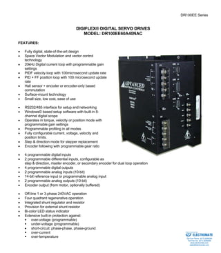
SPECIFICATIONS:
POWER STAGE SPECIFICATIONS DR100EE60A40NAC
AC SUPPLY VOLTAGE 40 – 270 VAC, 1 or 3-phase, 50 – 60 Hz
PEAK CURRENT 60A (42.4 Arms)
MAXIMUM CONTINUOUS CURRENT 30A (21.2 Arms)
MINIMUM LOAD INDUCTANCE 600 μH
SWITCHING FREQUENCY 20 kHz
HEATSINK (BASEPLATE) TEMPERATURE RANGE 0 to 65 ºC, disables at 65 ºC
POWER DISSIPATION AT CONTINUOUS CURRENT 400W
MIN. UNDER-VOLTAGE SHUTDOWN 55 VDC
MAX. OVER-VOLTAGE SHUTDOWN 439 VDC
BUS CAPACITANCE 1650 μF
SHUNT RESISTOR 20Ω, 100W internal
SHUNT SWITCH-ON VOLTAGE Programmable
SHUNT FUSE 5A Motor Delay @ 250VAC
AC LINE FUSING 3 x 20A @ 600VAC
MECHANICAL SPECIFICATIONS
AC SUPPLY CONNECTOR: C1 Screw terminal
SHUNT AND DC OUT CONNECTOR: C2 Screw terminal
MOTOR POWER CONNECTOR: P1 Screw terminal
MOTOR FEEDBACK CONNECTOR: CN3* 15-pin high density female D-sub
I/O CONNECTOR: CN2* 26-pin high density female D-sub
COMMUNICATIONS INTERFACE (RS232/485): CN1* 9-pin female D-sub
SIZE 9.24 x 6.37 x 5.96 inches
234.7 x 161.8 x 151.3 mm
WEIGHT
* Mating connectors are not included.
ELECTROMATE
Toll Free Phone (877) SERVO98
Toll Free Fax (877) SERV099
www.electromate.com
sales@electromate.com
4. ADVANCED MOTION CONTROLS DR100EE Series
Commutation sensor inputs. Internal
2K pull-up to +5VDC. Can be used
with single ended or differential Hall
sensors. I
Sold & Serviced By:
Page 4 of 7
PIN FUNCTIONS:
C1 – AC Supply Connector:
CONNECTOR PIN NAME DESCRIPTION I/O
1 AC1 I
2 AC2 AC supply input. 40 – 270 VAC, 3-
phase.
I
3 AC3
I
4 CASE GND Case ground GND
C1
5 NC Not connected -
C2 – Shunt and DC Out Connector:
CONNECTOR PIN NAME DESCRIPTION I/O
1 HV DC bus output O
2 PGND DC bus ground PGND
3 EXT. SHT External shunt resistor O
4 EXT SHT. External shunt resistor O
C2
5 INT. SHT. Jumper Jumper to C2-4 for internal shunt
resistor. Remove for external shunt. -
P1 - Motor Power Connector:
CONNECTOR PIN NAME DESCRIPTION I/O
1 MA Motor phase A O
2 MB Motor phase B O
3 MC Motor phase C O
4 PGND DC bus ground PGND
P1
5 HV DC bus output O
CN3 - Motor Feedback Connector:
CONNECTOR PIN NAME DESCRIPTION I/O
1 +Hall A I
2 +Hall B I
3 +Hall C
Encoder Input. For single
4 MOT ENC A+ I
5 MOT ENC A-Differential
ended encoder signals, leave the A–
terminal open. I
Encoder Input. For single
6 MOT ENC B+ I
7 MOT ENC B-Differential
ended encoder signals, leave the B–
terminal open. I
CN3
8 MOT ENC I+ Differential Encoder Input. For single
d d d i l l h I
I
ELECTROMATE
Toll Free Phone (877) SERVO98
Toll Free Fax (877) SERV099
www.electromate.com
sales@electromate.com
5. ADVANCED MOTION CONTROLS DR100EE Series
Sold & Serviced By:
Page 5 of 7
9 MOT ENC I-ended
encoder signals, leave the I–
terminal open. I
10 -Hall A* See CN3-1. Leave open in case of
single ended Hall sensors. I
11 -Hall B* See CN3-2. Leave open in case of
single ended Hall sensors. I
12 SGND Signal ground SGND
13 +5V OUT +5V @ 250mA max. Short-circuit
protected. O
14 PAI3 Programmable analog input, single
ended, 10-bit I
15 -Hall C* See CN3-3. Leave open in case of
single ended Hall sensors. I
* Contact factory for SE compatible options.
CN2 – I/O Connector:
CONNECTOR PIN NAME DESCRIPTION I/O
1 PDO1* Programmable digital output O
2 SGND Signal ground SGND
3 PDO2* Programmable digital output O
4 +REF I
5 -REF
Differential reference signal input, 14-bit
resolution. Can also be used as
programmable analog input 1. I
6 PAI2 Programmable analog input I
7 PAO1 Programmable analog output O
8 PAO2 Programmable analog output O
9 -PDI6 Programmable Input (see CN2-18) or
Direction- or Aux Enc B- I
10 PDO3 Programmable digital output O
11 PDI1 Programmable digital input I
12 PDI2 Programmable digital input I
13 PDI3 Programmable digital input I
14 PDO4 Programmable digital output O
15 +5V OUT
+5VDC. Note: the total current on CN2-
15 and CN3-13 combined should not
exceed 250 mA
O
16 SGND Signal ground SGND
17 +PDI5 Programmable differential digital input,
or Step+ or Aux Enc A+ I
18 +PDI6 Programmable, differential digital input
or Direction+ or Aux Enc B+ I
19 PDI4 Programmable digital input I
20 Encoder Channel A+ Output (from connector CN3),
O
21 Encoder Channel A-Encoder
not buffered O
22 Encoder Channel B+ O
CN2
23 Encoder Channel B-Encoder
Output (from connector CN3),
not buffered O
ELECTROMATE
Toll Free Phone (877) SERVO98
Toll Free Fax (877) SERV099
www.electromate.com
sales@electromate.com
6. ADVANCED MOTION CONTROLS DR100EE Series
24 Encoder Channel I+ O
25 Encoder Channel I-Encoder
Sold & Serviced By:
Page 6 of 7
Output (from connector CN3),
not buffered O
26 -PDI5 Programmable Input (See CN2-17) or
Step- or Aux Enc A- I
* Contact factory for SE compatible options.
CN1 - Communications Interface (RS232/485):
CONNECTOR PIN NAME DESCRIPTION I/O
1 SELECT RS232/485 selection. Pull to ground
(CN1-5) for RS485. I
2 TX/+TX RS232: Transmit; RS485: +TX O
3 RX/+RX RS232: Receive; RS485: +RX I
4 N/C Not connected
5 SGND Signal ground SGND
6 -TX RS485: -TX O
7 N/C Not connected
8 -RX RS485: -RX I
CN1
9 N/C Not connected
ORDERING INFORMATION:
Standard model: DR100EE60A40NACX
X indicates the current revision letter.
ELECTROMATE
Toll Free Phone (877) SERVO98
Toll Free Fax (877) SERV099
www.electromate.com
sales@electromate.com
7. ADVANCED MOTION CONTROLS DR100EE Series
Sold & Serviced By:
Page 7 of 7
MOUNTING DIMENSIONS:
ELECTROMATE
Toll Free Phone (877) SERVO98
Toll Free Fax (877) SERV099
www.electromate.com
sales@electromate.com