
Recommended
More Related Content
What's hot
What's hot (20)
Similar to OSI Model Explained
Similar to OSI Model Explained (20)
Recently uploaded
Recently uploaded (20)
OSI Model Explained
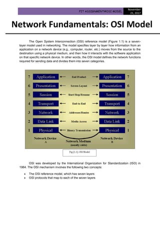
- 1. FIT ASSIGNMENT#OSI MODEL November 21, 2017 The Open System Interconnection (OSI) reference model (Figure 1.1) is a seven- layer model used in networking. The model specifies layer by layer how information from an application on a network device (e.g., computer, router, etc.) moves from the source to the destination using a physical medium, and then how it interacts with the software application on that specific network device. In other words, the OSI model defines the network functions required for sending data and divides them into seven categories. OSI was developed by the International Organization for Standardization (ISO) in 1984. The OSI mechanism involves the following two concepts: The OSI reference model, which has seven layers OSI protocols that map to each of the seven layers Network Fundamentals: OSI Model Fig (1.1): OSI Model
- 2. The seven layers of the OSI model, starting from the top, are as follows: Layer 7 Application Layer 6 Presentation Layer 5 Session Layer 4 Transport Layer 3 Network Layer 2 Data Link Layer 1 Physical The upper three layers are concerned with application issues, such as user interfacing and data formatting. The lower four layers relate to transport issues, such as data transmission and the physical characteristics of the network. It is essential to understand the OSI reference model from a design standpoint because of its modular architecture. The OSI model divides the specific tasks that are involved in moving the information from one networking device to another into seven smaller, more manageable groups of tasks/actions. The overall goals of the OSI model are to enhance interoperability and functionality between different applications and vendors, as well as make it easier for network administrators to focus on the design of particular layers of the model. For example, applications can be designed without having to worry about the lower OSI layers, because, if the packet has already been analyzed by the lower layers, there is a certain level of trust that the lower layers will process and send the packet over the wire successfully. The OSI model is a key concept in the networking industry and it plays an important role in the design phase of a network using a modular (layered) approach. Note: The OSI model represents the actions required to send data, but it does not specify how these actions are carried out. However, the OSI model does provide a framework for the communication protocols to be used between devices, where different protocols implement functions at various layers of the model. Protocols A protocol is a set of rules. Network devices need to agree on a set of rules in order to communicate, and they must use the same protocol to understand each other. A wide variety of network protocols exists at different OSI layers. For example, at the lower OSI layers, LAN and WAN protocols are used, while routed and routing protocols are found at Layer 3.
- 3. Protocols can be organized in protocol suites or stacks. TCP/IP is the most common network protocol suite, named after the two protocols in the stack. The TCP/IP suite can be found in almost all modern networks, and it is the core feature for the Internet and within organizations’ networks. Other examples of protocol suites are AppleTalk and Novell NetWare. The OSI layers and their associated protocols are described in the following sections, beginning with the highest layer of the model. Application Layer The Application Layer (Layer 7) is where the end-user interacts directly with an application. For example, when a user has information to transmit (e.g., data request, pictures, document file, etc.), the application layer interacts directly with any software application that communicates with the internetwork. Depending on the information the user wants to send over the network, a specific protocol is used, such as the following: The SMTP or POP3 protocol is used to send an e-mail message The FTP protocol is used to transmit a file over the network The Telnet protocol is used to control a remote device Presentation Layer The Presentation Layer (Layer 6) ensures that the data is understandable by the end system. In other words, the data must be converted and formatted in such a way that the system recognizes it and knows how to handle the content, so that information sent from one host can be interpreted properly by the destination host. This includes the translation and conversion required for formatting, data structure, coding, compression schemes for video and audio (e.g., MPEG, AVI, JPEG, GIF, and TIF files), encryption schemes, and character representation formats (e.g., ASCII to Unicode). In sum, if the packets from the Application Layer are sent unformatted, the Presentation Layer translates them and then passes them on to the Session Layer (Layer 5). Session Layer From a technical standpoint, communications systems are comprised of different service requests, and service responses between applications are located on different networking devices. The Session Layer (Layer 5) establishes, manages, and terminates these communication sessions and connects the lower layers with the Presentation and Application Layers. Transport Layer The Transport Layer (Layer 4) accepts data from the Session Layer and breaks it up into transportable segments. This layer is responsible for the information reaching the destination device error-free and in the proper order (i.e., sequence of packets); it is also responsible for the following: Reliability
- 4. Transmission error checking Error correction Data retransmission Flow control Sequencing Data multiplexing From a technical standpoint, all of these features are implemented by establishing a virtual circuit between the sender and the receiver devices. The Transport Layer initiates, maintains, and terminates these virtual circuits and uses segments as the protocol data unit. Segments are defined sets of data that include control information and are sent between the Transport Layers of the endpoints. The two main Transport Layer protocols used on the Internet are as follows: TCP (Transmission Control Protocol): a connection-oriented protocol UDP (User Datagram Protocol): an unreliable, low-overhead, connectionless protocol Connection-oriented protocols establish a logical connection and use sequence numbers to ensure that all data is received at the destination. Connectionless protocols only send the data and rely on the upper-layer protocols to handle error detection and to correct possible problems. Network Layer The Network Layer (Layer 3) is responsible for knowing the internetwork path (routing) from the sender device to the receiver device. It is also responsible for the logical addressing schemes (e.g., IP, IPX, and AppleTalk) that assign logical addresses to the network hosts on both sides of the communication path. The Network Layer sends datagrams (or packets), which contain a defined set of data that includes addressing and control information and is routed between the source and destination devices. If a datagram needs to be sent across a network that can handle only a certain amount of data at a time, the datagram can be fragmented into multiple packets and reassembled by the receiving device. If no fragmentation occurs, then a datagram is sent as a single packet. It is important to note that a datagram is a unit of data, while a packet is sent physically through the network. In addition to logical addressing schemes, the Network Layer is also responsible for router selection and packet forwarding, using the following types of protocols: Routed protocols (IP, IPX/SPX, AppleTalk, and DECnet) Routing protocols (RIP, EIGRP, OSPF, IS-IS, and BGP) Routed protocols are responsible for the actual rules and processes regarding the encapsulation of the data packets, and they are ultimately routed over the internetwork, whereas routing protocols actually move the routed protocol packets (Layer 3 data units) across the internetwork, from one router to another, using particular routing algorithms.
- 5. Data Link Layer The Data Link Layer (Layer 2) defines the format of the data that is transmitted across the physical network. This layer has two sublayers: the LLC (Logical Link Control) Sublayer and the MAC (Media Access Control) Sublayer (Figure 1.2). LLC deals with the Network Layer while MAC has access to the Physical Layer (Layer 1). The LLC Sublayer (IEEE 802.2) allows multiple network Layer 3 protocols to communicate over the same physical link by allowing those protocols to be specified in the LLC fields. The MAC Sublayer (IEEE 802.3) specifies the physical MAC address that identifies a device on a network. Each frame sent over the wire contains a MAC address field, and only devices with a specific MAC address can process the frame. A source MAC address field is also included in the frame. The Data Link Layer is responsible for reliable transmission of data across a physical network link, using specifications that provide different network and protocol characteristics, which includes physical addressing, different network topologies, error notifications, frame (Layer 2 data units) sequences, and frame flow control. Layer 2 is concerned with a specific addressing structure, namely physical addressing, as opposed to the Layer 3 logical addressing scheme. Physical addressing generally comes in the form of MAC addresses that are burned onto a computer network interface card (NIC) or on the interfaces of network devices. Physical Layer The Physical Layer (Layer 1) lies at the bottom of the OSI protocol stack and it represents the actual physical medium on which the information is travelling between network devices. As mentioned, Layer 1 interconnects with the Data Link Layer through the Figure 1.2 – Data Link Sublayers
- 6. MAC Sublayer, which controls the sending of the physical signals that encode 0 and 1 bits, or binary digits (e.g., electrical signals over a copper link). The following protocols operate at the Physical Layer: Local Area Network (LAN) protocols (Ethernet, IEEE 802.3, 100Base-T, Token Ring/IEEE 802.5, and FDDI) Wide Area Network (WAN) protocols (EIA/TIA-232, EIA/TIA-449, V.35, and EIA-530) Layer 1 defines physical media procedures, electrical and mechanical aspects, encoding, and modulation (voltage) on the line (i.e., the electrical signal is either a 0 or a 1, or is in a transition state), as well as activating, maintaining, and deactivating the actual physical link between multiple systems on LAN or WAN networks. Encapsulation In both LANs and WANs, packet transmission can be analyzed using the seven-layer OSI model. When data is transmitted by the source toward a specific destination, it passes through the Application, Presentation, and Session Layers and the protocol data unit arrives at the Transport Layer (Layer 4). At this layer, a 20-byte header is placed in front of the data. Regardless of whether the protocol is a reliable, connection-oriented protocol (TCP) or an unreliable, connectionless protocol (UDP), the data and the Layer 4 header, which together form a segment, is passed down to Layer 3, as illustrated in Figure 1.3 below: Figure 1.3 – Packet Encapsulation
- 7. The Network Layer places its Layer 3 header in front of the received segment and this group becomes a packet (or a datagram). The Layer 3 header contains important fields, such as the logical address (IP address) of both the source and the destination device. The newly formed packet is then passed down to Layer 2. The Data Link Layer creates a new data unit, called a frame, by adding the Layer 2 frame header and trailer. The frame is then passed down to the Physical Layer, which converts the information into 0 and 1 bits that are sent over the physical media using electrical signals (i.e., on a copper link). Finally, the data is sent over the wire using a wide variety of methods, such as Ethernet or Token Ring. The headers and trailers are a specific form of control information that allows the data to go through the network properly. Thus, the data at each layer is encapsulated in the information appropriate for the specific layer, including addressing and error checking. A Protocol Data Unit (PDU) is a grouping of data used to exchange information at a particular OSI layer. The Layer 1 to Layer 4 PDU types, signifying the group of data and the specific headers and trailers, are summarized as follows: The overall size of the information increases as the data travels through the lower layers (from Layer 1 to Layer 4). The destination device receives the data, and this additional information is analyzed and is then removed as the data passes through the higher layers, up to the Application Layer, where the data is unwrapped (or decapsulated). In addition to the Layer 3 logical addressing fields in the header, an addressing structure is also applied in the Layer 2 header (i.e., the MAC address). Every network device has a physical address burned onto it, which is located in a special field in the Data Link Layer header. This address changes as the packet passes from one device to another (e.g., from the source PC to a switch to a router to another switch and, finally, to the destination PC). However, the original IP source and destination addresses do not change when transiting the network because the packet is stripped of its Layer 3 header only when it goes beyond a router. When it stays within the same LAN, it only passes through switches, which decapsulate it at the Layer 2 header containing the MAC address. As a result, the header changes as the packet is re-encapsulated, as does the MAC address fields. Because different protocols are available at each layer (e.g., IP packets are different from IPX packets), proper network operation requires that both the source and the receiver endpoints communicate using the same protocol. Layer PDU Name Layer 1 Bit Layer 2 Frame Layer 3 Packet (Datagram) Layer 4 Segment