
Recomendados
Recomendados
Mais conteúdo relacionado
Mais procurados
Mais procurados (20)
Semelhante a Vellodrome Stadium ,London : Long span Structure
Semelhante a Vellodrome Stadium ,London : Long span Structure (20)
Mais de DanishPathan7
Último
Último (20)
Vellodrome Stadium ,London : Long span Structure
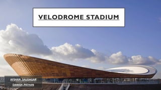
- 1. VELODROME STADIUM AFSHAN .SAUDAGAR DANISH .PATHAN
- 2. North OLYMPIC PARK MASTER PLAN • One of the most elegant new sports halls of Olympia 2012 is theVelodrome by Hopkins Architect. • In contrast to various other competition venues, the cycling arena with 6,000 seats created on the former East way Cycle Circuit site has been designed as a permanent building. SITE PLAN
- 3. 138 meters 120meters Location: London , United Kingdom Architects: Hopkins Architects Engineer: SBP, Stuttgart (Cable net) Roof Area: 12000 sqm Built up: 21,700 sqm Cable size: 36 mm in dia, 45 km (length) Completed: January 2011 Capacity 6000 Structural system: Form Active: (Cable Net) Vector Active(Rib Trusses) Span width: 138 mtrs 138meters INTRODUCTION
- 4. 48 Nos. Of Concrete Columns 2500 Sections of SteelTrusses Tension Cable net Timber panel with glazed glass at roof KEY ELEMENTS ExplodedView Of Velodrome Showing Load Carrying key elements Red Cedar Wood Facade Polyester Fabric coated with PVC ExplodedView Of Showing Climate Responsive key elements, & track
- 5. STRUCTURAL FORCE SYSTEM 1 2 3 4 5 4 3 2 1 5 Forces Acting on Structure Sr No Type Of Force Acting 1 Cable Tension Acts along the line of roof 2 Cable forces resisted by push pull in steel bowl truss 3 Push and pull transfer into Post tensioned concrete piers 4 Horizontal thrust provided through infield track 5 Supported toe external bridge acts as counter weight foundation TENSION COMPRESSION An Example of how tension acts n string
- 6. STRUCTURAL FORCE SYSTEM - TRUSSES Isometric Section Cable net nodes Ring Beam Main Truss Main Supporting Piers Truss gathering tension from the of and distributes them around . This Neutralize a large factor of the horizontal forces present in the roof cable and effectively isolates it from the rest of the structure 48 Trusses Arrange n perimeter of ring
- 7. SADDLE CABLE ROOF SYSTEM Positive Curvature Negative Curvature The Concept of the frame of the tennis racket could be fixed to the rim of a rigid bowl, then the bowl could help resist much of the tension, and the frame could be made much smaller Tension Cables Ring beam Tension in cable SADDLE ROOF ILLUSTRATION DEVELOPMENT OF FORM • The Opposite set of Two set of cable plays off each other • One set really one to go up and other really want to go down
- 8. CABLE NODES AND ROOF CONNECTING SYSTEM Aluminum Standing seam roof Top cable clamp Nut Steel washers Fabricated Steel Connection Plate Fabricated steel powder coated Receiver brackets Timber Roof Cassette 300 mm insulation provided Cover Plate Bottom cable clamp Steel middle cable clamp Components of connection between cable nets Bottom cable clamp Top cable clamp Fixture Detail Node Wooden ceiling panel attached to Cable Net Wooden Ceiling Panel Cable Net
- 9. NATURAL LIGHT AND VENILATION Reactions Under DifferentTemperature Natural Ventilation ,stack effect where cool air enters from bottom hot air gets out from top Under seat heating grilles beneath seat provide heat for competitive atmosphere Under floor heating from the in field keeps the track at daily use temperature Jet Powered heating nozzles installed in the upper tier based on shoot bust of air to alternate temperature quickly 28+ Degree Celsius 20-28 Degree Celsius 18 Degree Celsius 10-14 Degree Celsius Roof Plan Skylight installed High density polycarbonate sheets
- 10. CABLES, JACKS AND EXTERNAL CLADDING The cable net roof is composed of galvanized steel cables arranged in pairs, each with a diameter of 36 mm. Hydraulic jacks were used to tension the cable net until the ends of the cables could be attached to tension control bolts connected to the circular compression member of the primary structure Hydraulic Jack fixingTruss Lifting stages of Cable Cables laid loose over infield and clamped together at ground level Stage 1 of cable lift Stage 2 of cable lift – note slack cables in foreground 5,000 m² of red cedar wood were used for the wood façade
- 11. CONSTRUCTION PROCESS – 48,000 cubic meters of material was excavated to create the bowl for theVelodrome. – 900 piles were driven up to 26 meter’s beneath the ground to complete the foundation. – 2,500 sections of steelwork were installed to complete the steel structure of theVelodrome
- 12. TABLE OF MEMBERS AND SIZES SR NO MEMBERS SIZES PHOTO ADDITIONAL INFORMATION 1 Cable net 36mm in diameter With a 3.6m grid Hydraulic jacks were used to tension the cable net 2 Hydraulic jack 69 Nos. Hydraulic jacks were used to tension the cable net until the ends of the cables could be attached to tension control bolts connected to the circular compression member of the primary structure 3 Ring truss & Rib truss 48 Nos. These trusses are supported by sub steel columns on concrete piers
- 13. THANKYOU