
Recommended
More Related Content
Similar to Lab 2 Fluid Flow Rate.pdfMEE 491 Lab #2 Fluid Flow Rate .docx
Similar to Lab 2 Fluid Flow Rate.pdfMEE 491 Lab #2 Fluid Flow Rate .docx (20)
More from DIPESH30
More from DIPESH30 (20)
Recently uploaded
Recently uploaded (20)
Lab 2 Fluid Flow Rate.pdfMEE 491 Lab #2 Fluid Flow Rate .docx
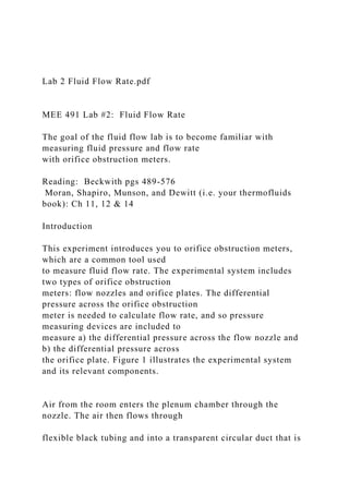
- 1. Lab 2 Fluid Flow Rate.pdf MEE 491 Lab #2: Fluid Flow Rate The goal of the fluid flow lab is to become familiar with measuring fluid pressure and flow rate with orifice obstruction meters. Reading: Beckwith pgs 489-576 Moran, Shapiro, Munson, and Dewitt (i.e. your thermofluids book): Ch 11, 12 & 14 Introduction This experiment introduces you to orifice obstruction meters, which are a common tool used to measure fluid flow rate. The experimental system includes two types of orifice obstruction meters: flow nozzles and orifice plates. The differential pressure across the orifice obstruction meter is needed to calculate flow rate, and so pressure measuring devices are included to measure a) the differential pressure across the flow nozzle and b) the differential pressure across the orifice plate. Figure 1 illustrates the experimental system and its relevant components. Air from the room enters the plenum chamber through the nozzle. The air then flows through flexible black tubing and into a transparent circular duct that is
- 2. instrumented with the orifice plate. Lastly the air flow enters the vacuum pump via more flexible black tubing and is returned to the room via the vacuum pumps outlet. Variable air flow through the system can be achieved by a rheostat knob that controls the vacuum pump. We will assume that any leaks in the system are negligible. Since the obstruction meters are connected in series, both obstruction meters measure the same mass flow rate (i.e. conservation of mass). In the case of the flow nozzles, two different sizes are provided. Both nozzles are standardized ASME long-radius flow nozzles with diameters of 1.265 cm and 2.530 cm for the small and medium nozzles, respectively. The orifice plate has a diameter of 0.795 in and is located in a pipe with a diameter of 2 in. Figure 1. Photograph of the experimental system and relevant components for part A of this lab The discharge coefficient, CD, is a very important performance parameter for an orifice obstruction meter. The discharge coefficient tells you the ratio of the actual orifice flow rate, Qactual, to the ideal orifice flow rate, Qideal: �! =
- 3. !!"#$!% !!"#$% [1] The ideal flow rate corresponds to the flow rate as derived from Bernoulli’s equation. Two of the assumptions that Bernoulli’s equation makes are isentropic and incompressible flow. While these are good approximations in many engineering situations, no real system is every truly isentropic and incompressible. Hence the discharge coefficient is always less than 1. In this lab you will determine the discharge coefficient for the nozzles as well as the orifice plate. Procedure • With the small nozzle measure at five different steady-state (i.e. make sure pressures are not changing with time) flow rates measure: o The differential pressure across the flow nozzle. o The differential pressure across the orifice plate with the most sensitive pressure measurement instrument possible for that flow rate. • With the large nozzle measure at five different steady-state (i.e. make sure pressures are not changing with time) flow rates measure: o The differential pressure across the flow nozzle. o The differential pressure across the orifice plate with the most sensitive pressure measurement instrument possible for that flow rate.
- 4. Note: You should have a total of 10 steady-state flow rate measurements (5 for the small nozzle and 5 for the medium nozzle) with differential pressures measured across the flow nozzle and orifice plate for each. Analysis • Calculate the mass flow rate of the system (see appendix) for each of the 10 flow rate measurements. • Based on conservation of mass, the discharge coefficient for the orifice plate can be calculated using the mass flow rate through the nozzle. Calculate the discharge coefficient of the orifice for each flow rate. Do these values agree with Fig.4 in the appendix? • Construct a calibration curve for the orifice plate. Plot the system’s mass flow rate versus pressure drop across the orifice plate on a log – log scale (i.e. the x- and y-axes should be on a log-log scale (i.e. the x- and y-axes should be on a log10 scale). • Determine the constant k and the exponent n in the general equation: ( )nPkm Δ= *! Appendix Calculation procedure to determine the mass flow rate in the flow nozzle in part A
- 5. 1. Infer the air velocity upstream of the nozzle (Hint: the “diameter” upstream of the nozzle is very large). 2. Calculate the air velocity at the nozzle’s exit using Bernoulli’s equation and the pressure drop across the nozzle. 3. Calculate the Reynolds number, Re=ρVD/µ, where ρ is the density, µ is the dynamic viscosity, and V is the average velocity, A the cross-sectional area at the nozzle’s exit. 4. Calculate the discharge coefficient, CD, of the nozzle using the empirical equation1: ( )[ ] ( )[ ] ( )[ ]32 Reln00020903.0Reln0097785.0Reln152884.019436.0 +−+=DC [2] 5. To calculate the actual volumetric flow rate, Qactual, the volumetric flow rate of an ideal orifice obstruction meter, Qideal, must first be calculated: ( ) ( ) ρ P AA A Qideal
- 6. Δ − = 2 * 1 212 2 [3] where A1 is the area upstream of the meter, A2 is the area of the orifice, ΔP = P1 – P2, P1 is the pressure upstream, P2 is the pressure downstream, and ρ is the fluid density (Hint: since the “diameter” upstream of the nozzle is very large, so is the “area” upstream of the nozzle). 6. The actual volumetric flow rate, Qactual, can then be calculated as: idealDactual QCQ *= [4] 7. The mass flow rate, m! , can then by calculated as: actualQm ρ=! [5] Note: For a given system with a known CD the actual volumetric flow rate can be expressed as:
- 7. where γ is a constant for the meter that includes ρ, A1, A2, and CD (note that equation [1] in lab 3 handout is exactly of this mathematical form). PQactual Δ=γ References: [1] Robert P. Benedict, “Most Probable Discharge Coefficients for ASME Flow Nozzles,” Journal of Basic Engineering, 88, 734 (1966) Figure 4 – Discharge coefficient vs. Reynolds number for an orifice plate (from NACA TM 952). Where d2/d1 is the ratio of the orifice diameter to the pipe diameter. lab 2.docx Surname 1 Maithah al-ali Tutor’s Name Class Information Date of Submission MEE 491 Lab #2 Fluid Flow Rate Introduction
- 8. Fluid flow is a significant part of several processes, such as material transportation from one point to the other, chemical reactions, and material mixing. Determination of fluid flow rates involves investigating flow in a network of pipes, and exploring different methods, such as, rotameters, and venturi meters for the flow measurement. The fluid flow through a pipe network has several engineering applications. The systems such as the turbines, heat exchangers, heat pumps, air conditioners, and wind tunnels are some of the few examples. The proper choice and use of the experimental instrumentations used in characterizing the fluid flow rates is essential component of verification of a design process Moreover, the properties of fluid flow measurement in a process is, in most cases, needed for producing and controlling the required products. The experiment also involves exploration of the impacts of the configuration of the pipe network, skin friction, pipe fittings, such as elbows, trees; and the drop in pressure across the pipe. This laboratory experiment introduces a student to the use of orifice obstruction meters, which are common tools used in measuring the rate of fluid flow. The experimental setup involved the use of flow nozzles, orifice plates, and two different orifice obstruction meters. The pressure difference across the meter is required to determine the fluid flow rates. Therefore, the devices for measuring pressure are also included for measuring the pressure difference across the nozzle and the orifice plate. Theory The mass conservation is an essential concept of engineering. Within some domain, the quantity of mass normally remains constant. According to the principle of conservation of mass, mass is neither created nor destroyed. The mass of any matter is simply the product of its density and the volume it occupies. For a gas or liquid, the volume, shape, and density can change with time within the domain. There is no mass destruction or accumulation through any pipe or tube carrying the matter. For a fluid in a tube, at any given plane that is perpendicular to the
- 9. tube’s middle line, the same quantity of mass will pass through. The quantity of matter through the plane is known as mass flow rate. The mass conservation, also known as continuity is a proof of the fact that quantity of matter passing through a section of fluid is constant. The value of the mass flow can be determined from the conditions of the flow. Mass flow is defined as the quantity of mass passing through a given cross-section area of a tube per unit time. From mass flow, volume flow can be determined easily. If a fluid passes through a tube of cross-section area A at a speed V, the volume flow is defined as the volume of fluid passing through a pipe per unit time. Mathematically, the volume flow is expressed as follows: Volume = Area * Velocity * time. The question many people have been asking is how the scientists and engineers apply the concepts of mass and volumetric flow rates in real life situations. From the Newton's Second Law of Motion, the forces of aerodynamic acting on an aircraft, such as drag and lift, are directly proportional to the rate of change of a gas momentum. The momentum can be defined as a product of mass of an object and its velocity. Therefore, the aerodynamic forces are expected to depend upon the rate of mass flow past an object. The thrust generated by a propulsion system is also a function of the rate of change of momentum of working gas. The thrust force is directly proportional to the rate of mass flow. For flow in a tubular section, the rate of mass flow is always constant. For constant-density fluid flow, if the velocity can be set at some known area, the velocity for any other known area can be determined easily. If a fluid velocity at a given time is required at a certain region, the area of that region must be calculated first. The fluid velocity is calculated from the general equation below: = The equation is commonly known as the equation of continuity and is very useful in the design of wind tunnels. Considering
- 10. the equation of the rate of mass flow, it appears that for a given area, the rate of mass flow can be made as large as possible by setting the fluid velocity high. Nevertheless, in the actual fluids, compressibility normally limits the velocity at which fluid flow can be forced through a region. In the events that there is a small constriction within the pipe, The Mach number of the flow through the constriction must be less than one. This phenomenon is commonly known as flow choking. It is important that one have a clear understanding of the flow structure in any tubular section before conducting an experiment. This will enable one to predict the experimental values. Objectives This experiment aims to demonstrate the measurement of rates of fluid flow using devices such as the orifice obstruction meters, which are common tools used in measuring the rate of fluid flow for incompressible flow in tubes. Moreover, energy losses in the devices will also be determined using the necessary equations, such as the steady-state energy equation and Bernoulli equation. Experimental Setup The setup for the experiment is as shown in figure 1 shown below. Figure 1: The experimental system and some necessary components for the lab The air from the lab enters the plenum-chamber via the flow nozzle. The air then flows via the flexible black tube onto the transparent circular duct connected with the orifice plate. Finally, the air flows into the vacuum pump through a more flexible black tube and is then returned to the laboratory room through the outlets of the vacuum pumps. The variable flow of air via the system can be realized by the use of a rheostat knob. The knob is used in controlling the vacuum pumps. In this laboratory experiment, it was assumed that any leakages in the
- 11. system are negligible. Because the obstruction meters are instrumented in series, both the meters measure the same rate of mass flow. For the case of the nozzles, two different sizes are given. Both the nozzles are standardized ASME long radius nozzles, with their diameters ranging from 1.265 cm to 2.530 cm. The diameter of the orifice plate is 0.795 inch and is instrumented within a pipe of diameter 2 inches. The coefficient of discharge, Cd is an essential performance parameter for the orifice obstruction meter. It is defined as the ratio of the actual flow to the ideal flow rate. The ideal rate of flow is normally the flow rate that is derived from the Bernoulli’s equation. The assumptions made while deriving an ideal flow rate is that the flow is incompressible and isentropic. Whereas these are good estimations in any scientific or engineering situations, it is not possible to realize a system that is completely incompressible and isentropic. Due to this fact, the coefficient of discharge is normally less than one. In this laboratory experiment, the discharge coefficient for the orifice plate, as well as the flow nozzles, were determined. Procedure 1. With the small flow nozzle at five dissimilar steady-state flow rates the following were measured; a. The pressure difference across the nozzle. b. The pressure difference across the orifice plate using the most sensitive pressure measurement device possible for that particular flow rate. 2. With the larger nozzle, the following were measured at five different steady-states: a. The pressure difference across the nozzle. b. The pressure difference across the orifice plate using the most sensitive pressure measurement device possible for that particular flow rate. A total of ten steady-state flow measurements were taken, i.e., five for small flow nozzle and five for large flow nozzle.
- 12. Results and Calculations The rate of mass flow of the system for the ten measurements are: [Insert the values as per your results] Based on the conservation of mass, the orifice plate coefficient of discharge can be calculated with the use of the rate of mass flow through the flow nozzle. The coefficient of discharge for each flow can be calculated as follow: [Calculte as per your results] The calibration curve for the orifice plate is as shown below: [Construct the calibration curve as per your values] The table of system’s mass flow versus the change in pressure across the orifice plate on a log – log scale is as shown below: The values are as shown in the table below: Change in Pressure, Δp ( Pascal) Log Δp Mass Flow Rate ṁ (Kg/s) Log ṁ
- 13. [Plot a the system graph here, the x and y-axes must be on a log 10 scale] From the graph, the values of the constant k and the exponent n are calculated as follows: Using the general formula, ṁ = k(Δp)n, where ṁ is the rate of mass flow, Δp is the differential pressure across the orifice plate, and k and n are constants whose values can be calculated as follows: From the general formula, ṁ = k(Δp)n, we can take log on both sides of the equation as follows: Log ṁ = log { k(Δp)n} This can be further expressed as: Log ṁ = nlog Δp + logk and comparing with a standard equation of a straight line graph, y = mx +c, n is the gradient of the graph, and log is the y-intercept of the graph. The value of k is now the antilog of y-intercept. Conclusion {This part is dependent on the experimental results. It is in order to supply the experimental result so as to draw a conclusion from them}
- 14. Appendix: Procedure on Determination of the Mass Flow Rate The following steps were followed in determining the various values of mass flow rate. 1. The air velocity was inferred upstream of the flow nozzle. 2. The exit velocity of air was calculated by using the Bernoulli’s equation and the change in pressure across the nozzle. 3. The third step is the determination of the Reynolds number. The number is calculated as follow: Re = ρVA/µ ------------------------------------------------------------ ----------------------------------- (1) Where ρ is the density, V is the velocity, A is the nozzle exit cross-section area, and µ is the dynamic viscosity. 4. The nozzle coefficient of discharge, Cd is then calculated by the use of the equation below: Cd = 0.19436 + 0.152884[In (Re)] – 0.0097785 [In (Re)]2 + 0.00020903[In(Re)]3 -----------(2) 5. The ideal orifice obstruction meter, Q ideal, is calculated first before calculating the actual volumetric flow. The ideal volumetric flow is calculated as follow: Q ideal = . ------------------------------------------------------------- ------------ (3) Where A1 is the meter's area upstream and is the orifice area, Δp = P1 – P2; P1 is the upstream pressure, P2 is the downstream pressure, and ρ is the density of the fluid. 6. The actual volumetric flow is calculated as follows: Qactual = CD x Qactual----------------------------------------------- ---------------------------------------- (4) The rate of mass flow is calculated as follows:
- 15. ṁ = ρQactual ---------------------------------------------------------- -------------------------------------- (5) Note: For a system with a known value of CD, the value of Qactual can be expressed as follow: Qactual = γ ------------------------------------------------------------ -------------------------------- (7) Where γ is the meter’s constant and is a function of the cross- section areas, the density, and the discharge coefficient. Works Cited Cotton, K. C. 'Discussion: ‘Most Probable Discharge Coefficients for ASME Flow Nozzles’ (Benedict, Robert P., 1966, ASME J. Basic Eng., 88, Pp. 734–744)'. Journal of Basic Engineering 88.4 (1966): 744. Web. This assignment provides you with an opportunity to read an article and then to share your thoughts about the article by
- 16. critiquing the details, including the decisions made. Access an Academic OneFile database. This article includes details and assertions about the ethical choices/decisions made by Edward J. Snowden, a former National Security Agency (NSA) contractor. Here is the reference citation for the article: Securing our liberty. (2013). Commonweal, 140(12), 5. After reading the article, draft a two-page response by discussing the U.S. government’s decision to acquire phone and internet data without disclosing its intentions to citizens. For this assignment, consider the NSA as an organization (i.e., business) and Snowden as a manager. How have the decisions of this event impacted the fairness of the U.S. government, its citizens, and Snowden? How did ethics, perhaps, influence Snowden’s decision to leak information? In this event, what is the greater good and also the consequences/sacrifices of that greater good? Based on the details of this event, what can we learn about making important decisions as a leader and manager? This event was covered by several news and media organizations, so there should be plenty of articles in the library. Conduct a bit more research in the online library related to this event involving Edward Snowden and the U.S. government—see what else you can discover about the event to determine an appropriate punishment, if any, for Snowden’s conduct. Include at least one additional source from the library in your response. The purpose of this assignment is for you to think critically about managers (and other leaders) making important decisions, and the process managers use to make important decisions. Consider how important it is to collect all of the facts before making an important decision, such as those involving fairness and ethics. Use APA Style to format your response. Proofread your work, and submit it in Blackboard for grading Original work only ATT00001
- 17. ATT00002 ATT00003 ATT00004 ATT00005 ATT00006 ATT00007 ATT00008 ATT00009 ATT00010 Sent from my iPhone IMG_2518.JPG IMG_2519.JPG IMG_2520.JPG