Case Planning to Final Restoration
•
0 likes•2,282 views

In this clinical case from Implant Practice US, Dr. Bart Silverman uses CBCT and CAD/CAM datasets to plan and place a restoration of a congenitally missing mandibular left second premolar. www.implantpracticeus.com

Recommended
More Related Content
Viewers also liked
Viewers also liked (10)
Recently uploaded
Recently uploaded (20)
Case Planning to Final Restoration
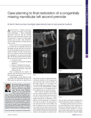
- 1. Advancements in implant placement — such as cone beam CT and CAD/ CAM technology — allow predictable restorative outcomes that are clinically efficient for doctors and take less time until final restoration. Through a complete digital workflow, we can plan a case, fabricate a custom-milled abutment, and fabricate and insert a crown. In this case, a 50-year-old male presented to my office with a congenitally missing left mandibular second premolar. Previously, a conventional bridge was placed, which ulti- mately had failed. His past medical history was non-contributory, and he was not taking any medications nor had any known aller- gies. We discussed options which included, after removal of the mobile deciduous molar: 1. Leaving the space 2. Fabricating a removable mandibular appliance 3. Placing a mandibular fixed bridge 4. Planning and placing an endosseous implant and restoration using CAD/ CAM technology. After considering all four options, he elected to have the deciduous tooth removed and a dental implant placed. Preoperatively, a cone beam CT scan was taken with Carestream Dental’s CS 9300 system to determine if sufficient bone was present to allow for implant placement. Carestream Dental’s CS 3D Imaging soft- ware was then used to plan the position of the implant (Figures 1-3). According to the Thommen single-stage surgical protocol, a 4.5 mm x 9.5 mm contact INICELL® implant was placed with a 3.2 mm gingival former in the mandibular left second premolar area. After 3 months of healing, osseointegra- tion was confirmed (Figure 4). At the same visit, the CS 3500 intraoral scanner was used to take an impression (Figure 5). To obtain digital impressions for fabrication of the patient’s custom abutments, we sectioned the mouth into sextants. The opposing arch was scanned from the canine distally, and then the gingival former was removed, and the involved arch also was scanned from the canine back (Figure 6). Once the two arches were scanned, the patient was asked to bite maximum intercuspation to obtain the bite. This was done by resting the unit against the teeth and taking three quick scans (Figure 7). We began by taking a tissue scan. Since we were fabricating a custom abutment, a fixture-level impression was taken next. In conventional implant dentistry, we would place a fixture-level impression coping and then take our impression; however, digital Case planning to final restoration of a congenitally missing mandibular left second premolar Dr. Bart W. Silverman shows how digital implant dentistry leads to more productive treatment Bart W. Silverman, DMD, is in private practice limited to Oral and Maxillofacial Surgery in New City, New York, and is an attending Physician at Westchester County Medical Center, Department of Oral and Maxillofacial Surgery, and Nyack Hospital, Department of Dentistry. He is also a Clinical Associate Professor at New York Medical College. He lectures nationally on several different implant systems and is president of the Bi-State and Hudson River Implant Study Clubs. He is a past president of the Rockland County Dental Society and previously served on the Board of Governors of the Ninth District Dental Society. Dr. Silverman graduated from Fairleigh Dickinson University in 1982 summa cum laude and received his doctorate in Dental Medicine in 1986 from Fairleigh Dickinson Jr. School of Dentistry, where he was a member of the Omicron Kappa Upsilon Honor Society. He completed his Oral and Maxillofacial Surgical residency at Westchester County Medical Center in 1989 and was Chief Resident during his final year. Dr. Silverman is currently a Diplomate of the American Board of Oral and Maxillofacial Surgery. Disclosure: Dr. Silverman is a paid speaker for Carestream Dental. Figure 2 Figure 3 Figure 1 Volume 9 Number 3 Implant practice 27 TECHNIQUE
- 2. dentistry allows us to place the digital coun- terpart to a fixture-level impression coping, called a scanning body, into the fixture. A periapical radiograph was taken to ensure proper placement and seating of the scan- ning body on top of the implant fixture. We used the CS 3500’s cutting tool feature to delete the top of the implant fixture and to use the tissue scan file to scan the scanning body without having to do a dupli- cate scan, saving us time. We then scanned the scanning body (Figure 8). Next, the scan- ning body was removed, and the gingival former replaced. Then the patient was sent home after a shade was picked for the final crown. The file was then saved, exported to the desktop, and sent via a secure web portal to our preferred lab. One of the benefits in digital cases such as this is the ability to send all of the informa- tion electronically. Of course, not all systems are created equal — some scanners use proprietary files, which can only be viewed by labs that have the right software. Fortunately, my scanner creates open-platform STL files that can be opened by any lab. While in conventional dentistry, we would take a fixed-level impression and send it to the lab to have an implant analog placed into the coping before the model was poured up in stone (allowing the lab to have an exact replica of the implant as it appeared in the mouth). Digital dentistry allowed us to obtain the same results in fewer steps (Figure 9). The file with the scanning body was pulled up on the computer, and the scanning body was used to allow a virtual placement of the implant into it so we could have a digital “model” of the exact location, angulation, and position of the implant as it appears in the mouth (Figure 10). The scanning body was removed by deleting it in the computer, and the custom abutment was planned. We have the ability to design the custom abutment any way we like. If we are planning to make a porcelain- fused-to-metal crown, we may want to make sure we have 2.5 mm of space for the metal and porcelain for our final crown restoration. If we are planning to do zirconia crown, we may need less space. We may want to bevel our buccal cusps or extend our lingual cusps up toward the central fossa of our opposing tooth. We may want to place grooves on the buccal and/or the lingual to be used for anti-rotation. This all can be planned into the custom abutment Figure 4 Figure 5 Figure 6 Figure 7Figure 8 Figure 9 Figure 10 28 Implant practice Volume 9 Number 3 TECHNIQUE
- 3. (Figure 11). In this case, we performed a restoration with porcelain-fused-to-metal. Once the design was approved, the information was sent to the milling machine for fabrication of the custom abutment (Figure 12). Most dentists in their first couple of cases will have a model printed with an implant analog inserted into it when they order it from the lab. After you feel comfortable with the technology, you can save $20-$30 per case if you do not ask for a model. In Figure 13, you can see the resin model with the custom-milled titanium abutment in place. Here we have one of two options: You can have the lab mill a crown after it is designed using the software as discussed previously, or the lab can fabri- cate a crown on top of the milled abutment. (We chose the latter for this patient.) This step is usually dependent on the digital lab that you are using. We then scheduled the patient for a crown insertion appointment. Unlike conventional crowns, which can take 25 to 30 minutes to place, the digitally generated crown required only a 5 to 10 minute inser- tion appointment. The patient was happy, not only with how the fabrication turned out (Figure 14), but also loved the ease and speed at which the process occurred. When comparing digital implant dentistry to conventional dentistry, aside from being a more exact technique, there are potential time- and cost-saving components as well. No longer must we set aside one operatory and one assistant and have them set up for the traditional “goopy” impression — which is time-consuming. After factoring in the time for taking conventional impressions and coupling it with the crown insertion appoint- ment, we are saving at least 1.25 hours with digital dentistry. We can now use this time to perform “productive dentistry” and do crown prep, or prep for a bridge or an endodontic proce- dure. Also, when comparing the cost for a traditional custom abutment with the cost of a milled model and abutment, the digital workflow is less. With the digital workflow, we are ultimately providing a better service for our patients, freeing up more chair time and decreasing our overhead. Figure 11 Figure 12 Figure 13 Figure 14 30 Implant practice Volume 9 Number 3 TECHNIQUE IP