(INDIRA) Call Girl Aurangabad Call Now 8617697112 Aurangabad Escorts 24x7
DC MOTORS.ppt
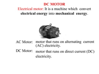
1. DC MOTOR
Electrical motor: It is a machine which convert
electrical energy into mechanical energy.
AC Motor: motor that runs on alternating current
(AC) electricity.
motor that runs on direct current (DC)
electricity.
DC Motor:
4. Function of each part of DC Motor:
Yoke:
•It is outer cover of dc motor also called as frame.
•It provides protection to the rotating and other part of the
machine from moisture, dust etc.
•Yoke is an iron body which provides the path for the flux
to complete the magnetic circuit.
•It provides the mechanical support for the poles.
•Material Used: low reluctance material such as cast
iron, silicon steel, rolled steel, cast steel etc.
5. Poles and Pole core:
• Poles are electromagnet, the field winding is
wound over it.
• It produces the magnetic flux when the field
winding is excited.
• The construction of pole is done using the
lamination of particular shape to reduce the power
loss due to eddy current.
pole shoe:
• Pole shoe is an extended part of a pole. Due to its
typical shape, it enlarges the area of the pole, so
that more flux can pass through the air gap to
armature.
• Material Used: low reluctance magnetic material
such as cast steel or cast iron is used for
construction of pole and pole shoe.
6. Field winding: field coil wound on
pole
• The coil wound on the pole core are called field coils.
• Field coils are connected in series to form field winding.
• Current is passed through the field winding in a specific
direction, to magnetize the poles and pole shoes. Thus
magnetic flux is produce in the air gap between the pole
shoe and armature.
• Field winding is also called as Exciting winding.
• Material Used for copper conductor is copper.
• Due to the current flowing through the field winding
alternate N and S poles are produced.
7. Armature core:
• Armature core is a cylindrical drum mounted on the
shaft.
• It is provided with large number of slots all over its
periphery and it is parallel to the shaft axis.
• Armature conductors are placed in these slots.
• Armature core provides low reluctance path to the
flux produced by the field winding.
• Material used: high permeability, low reluctance
cast steel or cast iron material is used.
8. Armature winding:
• Armature conductor is placed in a armature slots
present on the periphery of armature core.
• Armature conductor are interconnected to form the
armature winding.
• When the armature winding is rotated using a
prime mover, it cuts the magnetic flux lines and
voltage gets induced in it.
• Armature winding is connected to the external
circuit (load) through the commutator and brushes.
• Material Used: Armature winding is suppose to
carry the entire load current hence it should be
made up of conducting material such as copper.
9. Commutator
:
• It is a cylindrical drum mounted on the shaft along with
the armature core.
• It is made up of large number of wedge shaped
segments of hard-drawn copper.
• The segments are insulated from each other by thin
layer of mica.
• Armature winding are tapped at various points and
these tapping are successively connected to various
segments of the commutator.
Function of commutator:
• It converts the ac emf generated internally into dc
• It helps to produce unidirectional torque.
Material Used: it is made up of copper and insulating
material between the segments is mica.
10. Brushes:
• Current are conducted from the armature to the
external load by the carbon brushes which are held
against the surface of the commutator by springs.
• Function of brushes: To collect the current from the
commutator and apply it to the external load in
generator, and vice versa in motor.
• Material Used:
Brushes are made of carbon and they are rectangular in
shape.
11.
12. A machine that converts DC electrical power into
mechanical power is known as a Direct Current motor.
DC motor working is based on the principle that when
a current carrying conductor is placed in a magnetic
field, the conductor experiences a mechanical force.
The direction of this force is given by Fleming’s left-hand
rule and magnitude is given by;
F = BIL Newtons
According to Fleming’s left-hand rule when an electric
current passes through a coil in a magnetic field, the
magnetic force produces a torque that turns the DC motor.
The direction of this force is perpendicular to both the
current and the magnetic field.
14. Back emf:
• When the armature of a DC motor rotates under the
influence of the driving torque, the armature conductors
move through the magnetic field and hence emf is induced
in them as in a generator.
•The induced emf acts in opposite direction to the applied
voltage V (Lenz’s law) and is known as Back EMF or
Counter EMF (Eb).
The equation to find out back emf in a DC motor is given
below,
The back emf Eb(= PΦZN/60 A) is always less than the
applied voltage V, although this difference is small when the
motor is running under normal conditions.
15. Electrical circuit of a DC machine
E is the supply voltage, Eb is the back
emf produced and Ia, Ra are the armature
current and armature resistance
respectively then the voltage equation is
given by,
But keeping in mind that our purpose is to
derive the torque equation of DC motor we
multiply both sides of above equation by Ia
16. Now Ia
2.Ra is the power loss due to heating of the armature coil,
and the true effective mechanical power that is required to
produce the desired torque of DC machine is given by,
The mechanical power Pm is related to the electromagnetic
torque Tg as,
Now equating both ‘Pm’ equations we get
Here
17. Substituting ‘ω ‘ and ‘Eb ‘ in above equation we get:
This is the torque equation of DC motor. It can be further
simplified as
Which is constant for a particular machine and therefore
the torque of DC motor varies with only flux φ and
armature current Ia.
18. Types of DC Motor:
• Classification of the d.c. motor depends on the way of
connecting the armature and field winding of a d.c.
motor:
1. DC Shunt Motor
2. DC Series Motor
3. DC Compound Motor
Short shunt compound long shunt compound
Cumulative Differential Cumulative Differential
compound compound compound compound
motor motor motor motor
19. DC Shunt Motor:
• In dc shunt motor the armature and
field winding are connected in parallel
across the supply voltage
• The resistance of the shunt
winding 𝑅sh is always higher than the
armature winding Ra
• Since V and Rsh both remains constant
the Ish remains essentially constant, as
field current is responsible for
generation of flux.
thus ∅ ∝ Ish
• So shunt motor is also called as
constant flux motor.
20.
21. Applications of DC shunt Motor:
These motors are constant speed motors, hence used
in applications requiring constant speed.
Like:
1)Lathe machine
2)Drilling machine
3)Grinders
4)Blowers
5)Compressors
22. DC Series Motor:
• In this type of DC motor the armature
and field windings are connected in
series.
• The resistance of the series field
winding Rs is much smaller than the
armature resistance Ra.
• The flux produced is proportional to
the field current but in this If=Ia
Thus ∅∝𝐼𝑎
• Thus flux can never become constant in dc series
motor as load changes If and Ia also gets changed
• Thus dc series motor is not a constant flux motor.
23.
24. Applications of DC series Motor-
These motors are useful in applications where
starting torque required is high and quick
acceleration. Like:
1) Traction
2) Hoists and Lifts
3) Crane
4) Rolling mills
5) Conveyors
25. DC Compound Motor:
• The DC compound motor is a combination of the series
motor and the shunt motor. It has a series field winding
that is connected in series with the armature and a shunt
field that is in parallel with the armature. The
combination of series and shunt winding allows the
motor to have the torque characteristics of the series
motor and the regulated speed characteristics of the
shunt motor. Several versions of the compound motor
are:
• Short shunt Compound Motors
• Long shunt Compound Motors
26. Short shunt compound motor:
• When shunt field winding is connected in parallel with
armature like dc shunt motor and this assembly is
connected in series with the series field winding then
this type of motor is called as short shunt compound
motor.
• Depending on the polarity of the connection short shunt
motor is classified as:
1. Cumulative compound motor.
2. Differential compound motor.
27. Cumulative compound motor (short shunt):
• Figure shows a diagram of the cumulative compound
motor. It is so called because the shunt field is connected
so that its coils are aiding the magnetic fields of the
series field and armature.
• In this figure that the top of the shunt field is positive
polarity and that it is connected to the positive terminal
of the armature.
28. • The cumulative compound motor is one of the most
common DC motors because it provides high starting
torque and good speed regulation at high speeds.
• Since the shunt field is wired with similar polarity in
parallel with the magnetic field aiding the series field and
armature field, it is called cumulative. When the motor is
connected this way, it can start even with a large load and
then operate smoothly when the load varies slightly.
• You should recall that the shunt motor can
provide smooth operation at full speed, but it cannot start
with a large load attached, and the series motor can start
with a heavy load, but its speed cannot be controlled. The
cumulative compound motor takes the best characteristics
of both the series motor and shunt motor, which makes it
acceptable for most applications.
29. Differential Compound Motor (short shunt):
Differential compound motors use the same
motor and windings as the cumulative
compound motor, but they are connected in a
slightly different manner to provide slightly
different
operating speed and torque characteristics.
Figure shows the diagram for a differential
compound motor with the shunt field
connected so its polarity is reversed to the
polarity of the armature. Since the shunt field is
still connected in parallel with only the
armature, it is considered a short shunt.
30. In the above diagram you should notice that Fl and F2
are connected in reverse polarity to the armature. In
the differential compound motor the shunt field is
connected so that its magnetic field opposes the
magnetic fields in the armature and series field.
When the shunt field's polarity is reversed like this, its
field will oppose the other fields and the
characteristics of the shunt motor are not as
pronounced in this motor. This means that the motor
will tend to overspeed when the load is reduced just
like a series motor. Its speed will also drop more than
the cumulative compound motor when the load
increases at full rpm. These two characteristics make
the differential motor less desirable than the
cumulative motor for most applications.
31. Long shunt compound motor:
• when the shunt field is connected in parallel with both the
series field and the armature then this type of motor is called
as long shunt compound motor.
• Depending on the polarity of connection of shunt field
winding, series field winding and armature, long shunt motor
is classified as:
1. Cumulative Compound Motor.
2. Differential Compound Motor.
32. Applications of DC Compound Motor:
Cumulative Compound Motor:
• These motors have high starting torque.
• They can be operated even at no loads as they run at
a moderately high speed at no load.
• Hence cumulative compound motors are used for the
following applications.
1. Elevators
2. Rolling mills
3. Punches
4. Shears
5. planers
33.
34. • Since the the values of 𝑅𝑎 𝑎𝑛𝑑 𝑅𝑠 are small, the starting
currents will be tremendously large if the rated voltage is
applied at the time of starting.
• The starting current of the motor can be 15 to 20 times higher
than the full load current.
• Due to high starting current the supply voltage will fluctuate.
• Due to excessive current, the insulation of the armature
winding may burn.
• The fuses will blow and circuit breakers will trip.
• For dc series motors the torque T ∝ 𝐼𝑎
2. So an excessive large
starting torque is produced. This can put a heavy mechanical
stress on the winding and shaft of the motor resulting in the
mechanical damage to the motor.
• So to avoid all these effects we have to keep the starting
current of motor below safe limit. This is achieved by using
starter.
35. Principle of starter:
• Starter is basically a resistance which is connected in
series with the armature winding only at the time of
starting the motor to limit the starting current.
• The starter of starter resistance will remain in the circuit
only at the time of starting and will go out of the circuit
or become ineffective when the motor speed upto a
desire speed.
36. • At the time of starting, the starter is in the start position
as shown in fig. so the full starter resistance appears in
series with the armature. This will reduce the starting
current.
• The starter resistance is then gradually cut off. The motor
will speed up, back emf will be developed and it will
regulate the armature current. The starter is not necessary
then.
• Thus starter is pushed to the Run position as shown in fig
under the normal operating condition. The value of
starter resistance is zero in this position and it does not
affect the normal operation.
Types of starter:
1. Three point starter
2. Four point starter
37. Three point starter
A 3 point starter is a device that helps in the starting and
running of a DC shunt motor.
The presence of back emf (Eb), which plays a critical role
in governing the operation of the motor. The back emf
develops as the motor armature starts to rotate in presence
of the magnetic field, by generating action and counters the
supply voltage. Hence the back emf at the starting of the
motor is zero, but it develops gradually as the motor
gathers speed.
38. Three point starter
The general motor emf equation is:
Where E=Supply Voltage; Eb=Back EMF; Ia=Armature
Current; and Ra=Armature Resistance.
Since at starting Eb = 0, then E = Ia.Ra. Hence we can
rearrange for the armature current Ia
Ia=E/Ra
We can see from the above equation that the current
will be dangerously high at starting (as the armature
resistance Ra is small). This is why it’s important that
we make use of a device like the 3 point starter to
limit the starting current to acceptably low value.