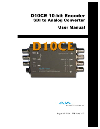
3. AJA D10CE 10-bit SDI to Component/Composite Converter User Manual — Introduction 3
Introduction
The D10CE converts Component Serial Digital (SDI) to analog Composite and
Component outputs—simultaneously. Four analog outputs are provided, plus two
equalized and re-clocked SDI loop-through outputs. The D10CE automatically
detects and configures to 525 or 625 line component digital input and then outputs
analog NTSC (525 line input), PAL (625 line input) or component as configured by
an 8-section DIP switch.
The full dynamic range of input component video values, below black and above
white, are not clipped when the D10CE encodes. When the D10CE is in its NTSC
mode, the 7.5 IRE pedestal can be disabled by DIP switch selection.
The component and composite outputs incorporate optimum chroma filtering and
1
independent pedestal configuration. An exclusive PLL jitter filter/memory reduces
the effects of SDI jitter on the output analog video. This feature, along with the
precision 4x oversampled D/A filters, provides high quality analog outputs, with very
low phase noise in the composite outputs.
Features
• High quality 10-bit encoding, 4 times oversampling
• SDI Input, SMPTE 259M
• Two loop-through SDI outputs (SMPTE 259M) (equalized and re-clocked
copies of the SDI input)
• Four analog outputs (configurable as 1 composite or sync, and R/G/B, Y/Pb/Pr,
or Y/C)i.
• Y/Pb/Pr selectable for SMPTE/EBU levels or Betacam levels (Y, R-Y, B-Y)
• Composite NTSC or PAL
• Configurable pedestal
• Digital noise reduction
• External DIP switch user interface for configuration
4. 4
Block Diagram
DIP
Switch
User
Interface
for
Feature
Selection
Serial
Video
In PLL Filter COMPOSITE or SYNC
10-bit D/A
ReClock Converter Jitter
Filter
COMPONENT OUTPUTS (selected by DIP switch)
Filter COMP B Y
Clocked Loop-through SDI Outputs
Filter Y G Pb
Filter C R Pr
Serial Video Out 1
Serial Video Out 2
D10CE 10-bit SDI to Analog Component and Composite Converter, Block
Diagram
I/O Connections
SDI Input
BNC Composite
and
Component
SDI Loop Output BNCs
Output 1
BNC Configuration
Determined by
SDI Loop DIP switch on
Output 2 other side of
BNC Converter
+ 5VDC
Power
Input
D10CE, Side View
5. AJA D10CE 10-bit SDI to Component/Composite Converter User Manual — User Controls 5
User Controls
1 The user interface for the D10CE is an 8-switch DIP
2 accessible through a cut-out in the bottom of the
3 unit. Use the DIP switches to configure outputs,
4
5 pedestal, blanking, and enable or disable noise
6 reduction.
7
8 Switches 1 through 3 control the COMPOSITE/
8 SYNC output BNC. Switches 4 through 8 control
the video format of the three BNCs below. The exact
function of each DIP switch and what it controls is
described on the following pages.
1
DIP Switches
OFF ON
Switch 1 Selects VIDEO or SYNC output from the Composite/Sync
BNC
:
ON OFF
Selects SYNC output for Selects composite video out
Component output (use when
the device being fed the
component signal requires a
separate sync signal)
Switch 2 Configure Pedestal For Composite/Sync BNC
:
ON OFF
7.5 IRE pedestal for NTSC No pedestal (also selects SMPTE
(also selects BETA 525 levels levels for YPbPr)
for YPbPr)
Note: There is no effect with 625 input.
6. 6
Switch 3 Configure Blanking For Composite/Sync BNC
:
ON OFF
WIDE Blanking: NARROW (NAR) Blanking:
Vertical— Vertical—
Line numbers indicate where video starts) Line numbers indicate where video starts
line 20, field 1; line 20, field 2 (525 line) line 13, field 1; line 12, field 2 (525 line)
line 23, field 1; line 336, field 2 (625 line) line 10, field 1; line 322, field 2 (625 line)
Horizontal— Horizontal—
Active video line duration Active video line duration's)
ITU-R/SMPTE (710 pixels NTSC, ITU-R.470 (720 pixels PAUNTSC)~-
702 pixels PAL)
Switch 4 Select Composite (CMPSTE) or Component (COMPNT)
Out
:
ON OFF
COMPNT: CMPSTE:
Selects component video output Selects composite video output
Switch 5 Select Video Format of Component Outputs
:
ON OFF
YUVNC: RGB:
Selects YPbPr/YC component output, if SW1 Selects RGB component output, if SW1 is set to
is set to “COMPNT,” “COMPNT”
Switch 6 Configure Pedestal For Component Output BNCs (3)
:
ON OFF
7.5 IRE pedestal for NTSC (also selects No pedestal (also selects SMPTE levels for YPbPr)
BETA 525 levels for YPbPr)
Note: There is no effect with 625 input.
7. AJA D10CE 10-bit SDI to Component/Composite Converter User Manual — User Controls 7
Switch 7 Configure Blanking For Component Output BNCs (3)
:
ON OFF
WIDE Blanking: NARROW (NAR) Blanking:
Vertical— Vertical—
Line numbers indicate where video starts) Line numbers indicate where video starts
line 20, field 1; line 20, field 2 (525 line) line 13, field 1; line 12, field 2 (525 line)
line 23, field 1; line 336, field 2 (625 line) line 10, field 1; line 322, field 2 (625 line)
Horizontal— Horizontal—
Active video line duration Active video line duration's)
ITU-R/SMPTE (710 pixels NTSC, ITU-R.470 (720 pixels PAUNTSC)~-
702 pixels PAL)
1
Switch 8 Configure Digital Noise Reduction
:
ON OFF
Enables Digital Noise Reduction on input. Disables Digital Noise Reduction
Output Selection The following table shows the combinations of DIP switch settings required to configure the
Matrix For Output three BNCs below the COMPOSITE/SYNC BNC.
2 (3 BNCs)
DIP Switch DIP Switch DIP Switch
Output Format
#4 #5 #6
1 Composite and 1 Y/C (Pedestal) CMPSTE N/A ON
1 Composite and 1 Y/C (no pedestal) CMPSTE N/A OFF
RGB COMPNT RGB OFF
RGB with pedestal COMPNT RGB ON
SMPTE component (BETA625)/ COMPNT YPbPr/YC OFF
EBU-N10
BETA 525 component COMPNT YPbPr/YC ON
8. 8
Installation
Typically, D10CE installation consists of the following:
1. disconnect +5VDC from the convertor
2. configure the DIP switch for the desired equipment configuration and video formats
3. connect video equipment to the convertor BNCs
4. apply +5VDC power to the converter ((AJA power supply model DWP)
Specifications
Item Specification
Serial Input SMPTE 259M 270MB, (SDI)
SDI Cable Equalization 300 meter 8281 typical
Serial Outputs Equalized, Re-clocked
Frequency Response +/- .15dB to 5.5MHz (Y)
+/- .15dB to 2.5MHz (Chroma - Component, RGB)
+/- .15dB to 1.3MHz (Chroma - Composite)
2T K factor < 0.5% (Y)
Differential Gain < 1 .5%
Differential Phase < 1 .5 degree
Y/C delay 10ns maximum
D/A Converters 10 bits, 4X oversampling
Signal Path 10 bits
Delay (input to output) 2.5us
Output level adjustment +/- 20% (internal)
Output level matching 1 .5% or 10mv (All outputs are separately buffered)
Power 5v DC regulated, 4 watt
(AJA power supply model DWP)
Size 147 x 79 x 25 mm
9. AJA D10CE 10-bit SDI to Component/Composite Converter User Manual — Specifications 9
1