SlideShare uma empresa Scribd logo
1 de 34
Baixar para ler offline
Building Technology 3 2012

TYPES ROOF TRUSSES

1|Types of Trusses
Building Technology 3 2012

Types
•

While many different trusses are available for roof construction, they can usually be
broken down into one of two basic categories. Flat trusses, known as parallel-chord or girders,
are used to construct flat roofs. Pitched, or common, trusses are used to build sloped-roof
structures. Hip, gambrel or bowstring designs are popular examples of common trusses.
Identification

•

All types of trusses have the same basic components and structure. The name "truss"
describes a triangular design, which may range from a simple individual triangle to a large
number of interconnected units. The outside framing members are known as chords, while the
smaller connecting members are called webs. A point where the truss rests on a load-bearing
wall is known as a bearing point, and a king post is a vertical support that divides the bottom
chord on many types of trusses.
Function

•

Roof trusses are used to carry and support the weight of the roof deck and any finish
material used to cover the roof. This weight can be quite significant if clay or slate roof tiles are
used, or it may be very light when used to support asphalt shingles or rolled roofing. The chords
support the roof while the webs brace and stabilize the chords, helping to distribute the load
across the entire truss to the bearing walls on either side.
Benefits

•

One of the primary benefits to truss construction is the ability to span much longer
areas than with traditional stick framing. Because trusses are designed by engineers, they are
also safer and more reliable than alternative materials. Truss roof systems can be erected much
more quickly and efficiently than framed roofs, and a variety of different truss designs are
available offer versatility to builders and homeowners.
Drawbacks

•

Because of the triangular shape of a truss, homeowners will find that roof trusses can
greatly reduce the amount of usable space in the attic. This can cause problems with storage, or
may even cut into potential living space. Trusses are also generally more expensive than stick
framing in terms of upfront cost, though the associated labor savings may offset this higher
material cost.

•

Common Trusses
•

A common roof truss is used to build a gable roof. In this system, two members called
top chords slope up from the eave line and meet at the roof peak; the roof sheathing is attached to
these chords. A bottom chord stretches horizontally between the top chords at the eave line. The
2|Types of Trusses
Building Technology 3 2012
points where the bottom chord meets the top chord are where the truss rests on bearing walls and
transfers the weight of the roof to the walls. A vertical king post rests on the bottom chord and
supports the peak of the truss, and a web system of short members helps to transfer the load from
the top chords to the bottom chord.
Scissor Trusses
•

A scissor truss is similar to a common truss, but in this design two bottom chords slope
upward from the eave line to the king post. In a common truss, the bottom chord functions as a
horizontal ceiling joist for the room below, while in a scissor truss, the slope of the bottom
chords form a cathedral ceiling. Other variations on the common truss can be used to form a
studio or tray ceiling.
Raised Heel Trusses

•

A raised heel truss offers both structural stability and room for more insulation, which
helps to increase a home's energy efficiency. The design raises and separates the top chord from
the bottom chord to produce extra space at the eaves. The net effect is an added extension to the
top of the exterior wall, allowing for the full depth of insulation to be applied in key areas above
the ceiling.
Dropped Chord Trusses

•

Dropped chord trusses are constructed with a secondary chord added below the bottom
chord. The additional truss prevents the ceiling from gradually bending upwards, and provides
extra space for full-depth insulation within the outer walls. The secondary chord also helps to
create an airtight vapor barrier. Dropped chord trusses offer several technical advantages, but
also suffer from financial disadvantages due to the added cost of installing taller studs, more
blocking and more siding.
Scissor Roof Trusses

•

Scissor trusses have their lower chords pointed upwards so that the lower chord
resembles an arrow that is pointing upwards, with the tip of the arrow intersecting below the
upper chord. The advantage of this design is that it allows space beneath the roof for constructing
a cathedral ceiling. This design also helps eliminate the necessity of a load bearing wall in the
center of the structure. The sloped ceiling coupled with the limited space can make it difficult to
install insulation when working on this type of trusses.
Parallel Chord Trusses

•

Parallel chord roof trusses, or flat trusses, are constructed with two chords running
parallel to each other and supported by reinforcing trusses in between the top and bottom chords.
The biggest advantage of this type of design is that it provides space for easy installation of
generous amounts of insulation. Among the disadvantages of using this type of design are
increased costs due to the additional steel braces and the difficulty of insulating the space
between chords.
Attic Trusses
3|Types of Trusses
Building Technology 3 2012

•

Attic trusses are designed to provide an inexpensive way of creating additional storage
space in a new home. Attic trusses resemble conventional "common trusses," but leave an empty
space in the center to accommodate an extra room. Reinforcing trusses are placed on both sides,
and above the room constructed in the center of the trusses. Attic trusses can provide more living
or storage space, but will cost more to construct.
Bowstring Trusses

•

Bowstring trusses, or Belfast trusses, are similar to conventional "common trusses"
except for the top chord, which is constructed in a parabolic design. Bowstring trusses resemble
the arched shape of an archery bow. The curved top chord and the horizontal bottom chord
intersect each other at both ends. Bowstring trusses are designed to span large distances, such as
those required for the roof of an aircraft hanger or warehouse.
Gambrel Trusses

•

Gambrel trusses are constructed symmetrically with four slopes on the top chord. Two
slopes are placed on each side with the lower slopes positioned at a steep angle and the upper
slopes relatively flat. Gambrel trusses provide more room below the center of the trusses since
the limited framing in the middle of the trusses increases floor space. Extra flat space for
windows and skylights is also created by constructing the bottom chords at a steep angle.
Types of Steel Trusses
Steel trusses are built on exactly the same principles as wooden trusses, and any truss that can be
built of wood can also be built of steel, but owing to the different nature of the two materials, the
types of trusses best adapted to wooden construction are not the most economical for steel.
Steel trusses are generally built of angles, channels, plates and eye bars, and as any of these
shapes are better adapted to resisting a tensile stress rather than a compressive stress, economy
requires that the form of the truss or arrangement of the members, shall be such that there shall
be as few members in compression as practicable, and that the shorter web members shall be
in compression and the longer ones in tension.
Almost any combination of triangles can be made to support a roof, when built of steel, but some
combinations will require a much greater weight of metal, to support the given load than others.
Steel roof trusses having a span of less than 100 feet can generally be built more cheaply with
riveted connections, or joints, and most of the arched trusses for wide spans, are also riveted
together. For some types of trusses, however, the pin connection may be cheaper or more
advisable construction.
Pin connected trusses may be more conveniently shipped, and where they are supported by
brickwalls, may sometimes be more economically erected.

4|Types of Trusses
Building Technology 3 2012
Riveted trusses are almost always built of angles for the ties, and of a pair of angles or channels
for the struts, the angles often being reinforced by a web plate. In pin-connected trusses eye bars
are generally used for the ties, and a pair of channels, latticed or reinforced by plates for the
struts.
Number Of Struts Or Panels
The best form for a steel truss, and the most economical number of braces will depend in a great
measure upon the inclination and construction of the roof, as well as upon the span. If purlins are
used to support the jack rafters then the distance between the struts may be as great as 12 feet,
but if there are no jack rafters and the planking of the roof is nailed directly to the purlins, then
the latter should not be placed more than 8 feet apart, and if the roof is covered with corrugated
iron secured to the purlins, then the purlins can not be more than 5 feet on centres. Whenever
the purlins are more than 4 feet apart, they should come over the end of a strut or brace, to avoid
bending moments, consequently the spacing of the purlins will generally determine the
number of struts in each half of the truss. For this reason the same form of truss may be
required for a span of 40 feet as for a span of 80 feet, but, of course, the members will not be as
heavy in the forty-foot truss as in the one with greater span.
When the truss rafter is subject to a transverse strain, that is, when it is loaded between the
joints, the distance between the joints should not exceed 9 feet and preferably 7 or 8 feet,
depending somewhat on the distance the trusses are apart.

Fig. 64.
Trusses For Pitch Roofs
For ordinary conditions and for spans less than 100 feet some one of the types shown by Figs. 64
to 75, will generally meet the requirements of strength and economy.
For a narrow shed or shop the shape of truss shown by Fig. 64 is the most economical, the truss
proper being that portion enclosed within the points A, B, C. This truss is practically the same as
that shown by Fig. 65.
5|Types of Trusses
Building Technology 3 2012
For spans of from 24 to 48 feet, and with an inclination not exceeding 6" to the foot, types 66
and 67 are the most suitable.
The truss type represented by these two figures has received the name of "Fan truss." The truss
shown by Fig. 65 is known as a "simple Fink truss." The truss shown by Fig. 67 differs from
that in 66, principally in the inclination of the braces. The braces A, B, in Fig. 67 being inserted
to brace the truss from the column to prevent racking under wind pressure. Fig. 67 should be
used when the truss is supported by columns, and Fig. 66 when the truss rests on brickwalls.
When the roof construction demands three purlins on each side of the truss, one of the forms
shown by Figs. 68, 69, 70 or 71 should be used.

Fig. 66. - Simple Fink Truss; Span, 20 to 36 ft.

Fig. 66. - Simple Fan Truss.

Fig. 67. - Fan Truss; Span, 40 to 50 ft.
The names given to these trusses are often confounded by different writers; many engineers class
the French and Fan trusses with the Fink truss. The term "French" appears to be generally
given to those trusses in which the tie-beam is raised in the centre. The truss shown by Fig. 71,
appears to have no generally recognized name. One writer refers to it as an "English" truss. This
6|Types of Trusses
Building Technology 3 2012
truss is not as economical as the Fink truss, except when the inclination of the rafter is less than
one-fourth pitch, on account of the great length of the inner struts.

Fig. 68. - Compound Fink Truss.

Fig. 69. - Eight-PanelFrench Truss.
Although Fig. 71 somewhat resembles the Queen truss, Fig. 12, it will be seen that the diagonals
run in the opposite direction, the diagonals in Fig. 71 being in tension, and the verticals in
compression, the reverse of the Queen truss.
Much of the economy of Fink and Fan trusses lies in the fact that most of the members are in
tension and the struts are short. Comparing Figs. 70 and 71, it will be noticed that the inner strut
in the former is only 1/3 as long as the strut in the latter. Another advantage of these trusses is
that a partial load, as, for instance, a wind or snow load on one side of the truss never causes
stresses in excess of those produced by a uniform load of the same intensity over the whole truss.
As a general rule, the struts in Fink trusses are placed at right angles to the rafters, as in Figs. 68,
72 and 73, but if there are trussed purlins it is desirable to have vertical members to receive the
ends of the purlins. Vertical struts are generally required in hip trusses.

Fig. 70. - Fink Truss with Vertical Struts.

7|Types of Trusses
Building Technology 3 2012

Fig. 71. English Truss

Depth Of Fink And Fan Trusses
The depth of these trusses at the centre is usually determined by the roofing material that is to be
used. Thus, slate should not be used on a roof in which the rise is not equal to one-thirdof the
span; the rise for wood shingles should not be less than one-fourth of the span, and for
corrugated iron not less than one-fifth of the span.

Fig. 72. - Ten-Panel Fink Truss.

Fig. 73. - Twelve-Panel Fink Truss.
Considering the construction of the roof and the weight of the trusses, the most economical pitch
for a roof is about 1/4 the span, or what is commonly called a quarter pitch, the rise of the rafters
being 6" in 12" or 26 degrees and 34 minutes. When the rise is less than 1/6 of the span some
other type of truss will generally be required. When the inclination of the roof is determined
almost entirely by the question of economy the rise is generally made from 6 to 7 inches in 12
inches.

8|Types of Trusses
Building Technology 3 2012
Cambered Trusses
With Fink or Fan trusses having an inclination for the rafter not exceeding 30 degrees it is more
economical to employ a horizontal chord or tie since it obviates bending of the laterals. Raising
the bottom chord, also materially increases the strains in the truss members, hence it increases
the cost. A truss whose bottom chord has a rise of two or three feet, as in Fig. 69, presents a
better appearance, however, than one with a horizontal chord, and for steep roofs, it will
generally be fully as economical to raise the bottom chord because of the shortening of the
members. Trusses with raised ties are designated as "Cambered."

Fig. 74. - French Truss with Vertical Struts. Span, 80 ft.
33. The diagram shown by Fig. 75 represents 1/2 of one of the steel trusses used in roofing a car
barn for the North Jersey Railway Co., atNewark, N. J. There were 13 of these trusses, spaced 19' 2 1/4" on centres, each
having a span of 98 1/4' between the centres of the supporting columnsto which the truss is
riveted by splice plates engaging the end connection plate and the end web of the column. The
dimensions of the principal members of these trusses are indicated in connection with the
illustration. These trusses were shipped in four sections which were assembled in a horizontal
plane and riveted up complete at the surface of the ground. The bottom chord was stiffened by
lashing a rail on each side of it for its entire length and a sling being attached to the apex of the
top chord, the truss was lifted and set on top of the columns by an 8" x 8" gin-pole 50 feet high.
The roofing consists of corrugated iron supported by 5" I-beam purlins weighing 10 lbs. to the
foot, spanning from truss to truss and bolted to the rafters with two bolts at each end; the general
spacing of the purlins being 4' 9 3/4". This may be considered as an example of an extremely
light roof, the weight of each truss being only about 4,200 lbs., and the entire weight of the truss,
purlins, bracing of the lower chord and corrugated roofing being only 8 lbs. for each horizontal
foot of surface covered. The truss shown by Fig. 74 was designed for the roof of a drill hall
having a span of 80' and with a spacing, centre to centre, of 20'. The roof was to be constructed
with 2x8 rafters supported by purlins at points A, B, C, D, E, and F. Sash were to be placed in
the rise C D to light the interior of the building. The joint at X was located with reference to the
9|Types of Trusses
Building Technology 3 2012
position of the gallery rod; if there had been no gallery it would have been more economical to
space the vertical struts uniformly as in Fig. 70.
Dimensions of Members in Fig. 75.
Rafters.. 1 - 2 = 2 - 5"

x 3 1/2" x 7/16" L's.

Rafters.. 2 - 3 = 2 - 5"

x 3 1/2" x 3/8" L's.

Main tie.. 1 - 4 = 2 - 5"

x 3 1/2" x 3/8" L's.

Main tie.. 4 - 5 = 2 - 3 1/2" x 2 1/2 x 5/16" L's.
a, a, a.......

= 2 - 2 1/2" x 2"

x 1/4" L's.

b, b, b.......

= 1 - 2 1/2" x 2"

x 1/4" L.

= 2 - 3"

x 2 1/2" x 1/4" L's.

= 2 - 3 1/2" x 2 /2" x 5/16" L's.

Fig. 75. - Diagram of Compound Fan Truss.

10 | T y p e s o f T r u s s e s
Building Technology 3 2012
Fig. 7G. - Warren Triangular Truss.

Fig. 77.
For roofs having a span of 80 to 100 feet, and a rise of from one-fourth to one-thirdof the span,
the Warren triangular truss shown by Fig. 76 is a good type. This truss is best adapted to pin
connections.
For a steep roof, the type shown by Fig. 77 is about as economical as any. A complete example
of this type of truss with the details of the computations is given in Part II., of Berg's "Safe
Building."
The plus sign adjacent to a member, in all the trusses illustrated, denotes that the member is in
compression, while the minus sign denotes tension. In Figs. 76 and 77 the members represented
by single lines are in tension. The members above the main rafter as C D, D E, and E F, in Fig.
74, and a and b in Fig. 75 do not form a part of the truss proper but are merely a frame work to
support the elevated roof and in drawing the stress diagram, they should be omitted 34. FINK
TRUSSES WITH PIN JOINTS. - Fig. 78 shows one-half of a Fink truss designed for pin
connections. This truss has a span of 55' 4" between centres of end pins and the distance between
the centres of trusses is 6'. The roof is covered with 12" x 20"slate, secured to 1 1/2 x 2 1/4"
angle purlins weighing 3 lbs. to the foot and spaced 8 1/2" on centres. The angles span from truss
to truss and are bolted to the deck beam with 1/2" bolts. A 1 1/2" by 2 1/4"nailingstrip is fastened
to every third purlin for securing matched ceiling placed on the underside of the roof. Complete
details of this truss were published in "Architecture and Building" for January 18, 1890.
Fig. 79 shows details of the cast-iron struts.
This truss, being put together entirely with bolts and pins, could easily be erected with unskilled
labor. 35. TRUSSES FOR FLAT ROOFS.
- For supporting flat roofs or roofs having a fall not exceeding 1" to the foot, one of the types
shown by Figs.
80 to 84 will generally be found economical. The choice of the particular type depending
somewhat on the span and whether the truss is supported by columns or by brick or stone walls.
For spans up to 50' either of the forms shown by Figs.
11 | T y p e s o f T r u s s e s
Building Technology 3 2012

Fig. 78. - Fink Truss with Pin Connections, lower chord between the end joint and the wall, Fig.
80, has no stress from the roof load but is put in to brace the wall, and to stay the truss. In trusses
supported by brick walls this type is preferable to that shown by Fig. 81, while the latter is more
suitable when the roof is supported by columns. The vertical A, Fig. 81, is in- 80 or 81 will
answer all practical requirements. The truss shown by Fig. 80 is intended to be used where the
fall of the roof is at right-angles to the truss; this truss can be built, however, with an inclination
to the top chord as in Fig. 81. The end brace in Fig. 80 is in tension while in Fig. 81 it is in
12 | T y p e s o f T r u s s e s
Building Technology 3 2012
compression. The portion of the inserted to receive the tension or compression from the brace B,
and would have no stress from the roof load. The truss shown by Fig. 82, which represents an
actual truss is known as a "Double Warren Truss" and is desirable where it is important to make
the trusses as shallow as practicable; it can be built with light members and makes a very stiff
roof, being especially suitable for roofs supported by steel columns. The strength of this truss
under unsymmetrical loads, as, for example, when there is more snow on one side than on the
other, would be materially increased by putting a vertical tie in the center as shown by the dotted
line; without this member the braces AA, if subject to any stress whatever, would produce a
bending in the bottom chord at the center. Fig. 83 represents an actual roof truss with a span of
57' supported by steel columns. The entire load on the truss is transmitted to the columns by the
braces B, B, which are in tension. Fig. 84 shows a Warren truss of 96' span over a pier shed, New
York City.

Fig. 79. Details of Struts in Fig. 78.

Fig. 80. - Span, 56 ft.
13 | T y p e s o f T r u s s e s
Building Technology 3 2012

Fig. 81. - Span, 30 to 36 ft.

Fig. 82.-Span. 50 ft.

Fig. 83. - Span. 57 ft.

Fig. 84. - Span, 96 ft.
The plus and minus signs in these illustrations indicate compression and tension, respectively,
under uniform dead load. The plus and minus sign together indicate that the member may be
subject to either tension or compression, according to the direction of the wind or to an uneven
distribution of snow. In most of these trusses an unsymmetrical load may change the stress in the
diagonals neat the centre of the truss. Trusses like those shown by Figs. 80-84 are almost
invariably built with riveted connections and with angle or channel shapes for all members.
For Horizontal Steel Trusses Intended to Support Floor Loads, the Pratt truss shown by Figs. 85
and 86 is best adapted, the members indicated by double lines being in compression, and those
indicated by single lines in tension. When supporting floors subject to moving loads, counter ties
should be inserted as indicated by dotted lines. For this truss, pin connections are generally
14 | T y p e s o f T r u s s e s
Building Technology 3 2012
employed and are preferable to riveted connections. When properly proportioned this truss is
capable of sustaining almost any load.

Fig. 85. - Pratt Truss; Span, 60 to 150 ft.

Fig. 86. - Suspended Pratt Truss; Span, 40 to 80 ft.
The Quadrangular Truss
The truss shown by Fig. 83 is known as a quadrangular truss, although the more common shape
for this truss is that shown by Fig. 87. This truss may be considered as two trussed rafters, held in
place by the tie T at the centre. The portions of the truss which are in compression are indicated
by double lines while the single lines represent the tension members. The dotted lines represent
counter-braces or ties, which might be brought into action in case of a heavy snow load on one
side only or during a severe gale.
The piece B has no strain when the truss is subjected only to a vertical load, although it is usually
put in to brace the post P, which carries the entire load transmitted to the support. This truss is
well adapted to steel construction up to spans of 180 feet. When the span exceeds 100 feet, and
the truss rests on a brickwall one end of the truss should be supported on rollers to allow for
expansion and contraction in the steel. The proportions of the truss shown in Fig. 87 are those of
the roof trusses of the Jersey City-station of the Central Railroad of New Jersey. The trusses in
this building have a span of 142 feet 4 inches, centre to centre of bearings, with a depth in the
centre of 24 feet 4 inches. The distance between trusses is 32 feet 6 inches. The joints are pinconnected, eye-bars being used for the tension members, and one end of the truss is on rollers.
Fig. 88 gives the proportions of similar trusses over the amphitheatre of the Madison Square
Garden, New York.* In both of these trusses the posts and braces at the ends are made a part of
the truss, although they cannot be represented in the strain diagram, and the post P receives the
whole load from the truss at its upper end, the diagonal tie transmitting the entire web stress to
the top of the post. The brace B should be so constructed as to resist both tension and
compression. This truss, like the other, is pin-connected, with eye-bars for the tension members.
The principal dimensions of the truss are given in the drawing.
15 | T y p e s o f T r u s s e s
Building Technology 3 2012

Fig. 87. - Typical Quadrangular Truss.

Fig. 88. - Truss over Amphitheatre; Madison Square Garden.
* Details of these trusses were published in 'Architecture and Building" for April 21, 1890.
Fig. 89 shows another exampl eof this type of truss with intermediate supports for the purlins.
The truss shown by Fig. 90 also belongs to this type, but differs from the trusses shown by Figs.
87-89, in that the diagonals are all in the same direction. This causes a reversal of the stresses in
the web members, as indicated by the plus and minus signs, the three diagonals at each side of
the centre being in compression and the adjacent uprights in tension. In the trusses shown by
Figs. 87-89, all of the diagonals are in tension and all the verticals in compression. The truss
proper, is included within the figure A, B, C, E, D.

16 | T y p e s o f T r u s s e s
Building Technology 3 2012

Fig. 89. - Span, 102 ft.

Fig. 90. - Quadrangular Truss; Span, 80 ft.
It may be noticed that the lower chord of these trusses is segmental in shape, giving a graceful
outline, and also the most economical proportions for wide spans.
For shorter spans a full semicircle or semi-ellipse may be obtained by giving a greater curve to
the lower chord and continuing it by means of braces. Fig. 91 shows how this was accomplished
in the roof trusses over the wings of the Manufacturers' and Liberal Arts Building of the World's
Columbian Exposition at Chicago.
The parts included between the joints A, B, C, D form a quadrangular truss, while the portions X,
X are merely braces external to the truss.
17 | T y p e s o f T r u s s e s
Building Technology 3 2012

Fig. 91.
The trusses supporting the central roof of the Mining Building, represented in Fig. 111, are also
of the same type; although in this building the lower chord and braces have the form of a semiellipse. In both of these figures the tension members are represented by single lines. All the
members in this truss were made of angles, so as to take up either tension or compression, and
the joints were riveted.
The stresses in quadrangular trusses due to wind and snow should be determined independently
of the dead load, and the members computed for the maximum stress that may be produced by
any possible combination of loading.
There are numerous examples in this country of quadrangular trusses of from 100 to 180 feet
span.
The truss shown by Fig. 92, which is a diagram of one of the trusses over the Kansas City
Auditorium, may be considered as a cross between the Warren truss and the Quadrangular truss,
for if the end panels were omitted the truss would be almost identical in shape to that shown by
Fig. 90. This truss has pin connections at the joints. The three diagonals each side of the centre
are formed by lattice channels, and all of the ties are formed by eye-bars. The plus sign denotes
compression and the minus sign tension. The diagram below the truss drawing shows the manner
in which the trusses were braced laterally. All measurements are from centre of pins. A
description of this truss and of the building may be found in the "Engineering Record" for July
22, 1899.
Arched Trusses
For open roofs of wide span arched trusses are generally the most economical, and as a rule give
the most pleasing appearance.
The economy of an arched truss lies in the fact that the principal compression members follow
approximately the line of greatest strain, so that the bracing can be made very light. Thus, if the
frame shown in Fig. 93 is so built that the joints come in the line of a parabola with the lower
ends secured by a horizontal tie, and all the joints are uniformly loaded, the frame will remain in
equilibrium without bracing. In practice perfect equality of loads cannot be maintained, and the
18 | T y p e s o f T r u s s e s
Building Technology 3 2012
weight of the tie must also be supported from the upper chord, so that to make a practical truss it
is necessary to introduce bracing between the arched rib and the tie, either as shown in Fig. 94 or
Fig. 95.

Fig. 92. - Elevation of Truss and Plan of TwoTrussesShowing Lateral Bracing.
The braces provide for the inequality of the loads, and the tension members take up the thrust in
the braces. The effect of the inequality of the loads, however, is usually such that only very slight
strains are brought upon the bracing, so that the amount of material required for a truss of this
shape is considerably less than in a truss with a straight rafter. That the framework shown in Fig.
93 shall be in equilibrium, the joints must be in the curve of a parabola, but as bracing is always
necessary, the upper chord may have the form of the arc of a circle without greatly increasing the
strains in the bracing.

Fig. 93.
Trusses of the types shown in Figs. 94 and 95 have been more extensively used for bridges than
for roofs, as they are not so well adapted to the usual conditions of roof construction. For a
segmental or parabolic roof, however, this type makes a very economical truss.

19 | T y p e s o f T r u s s e s
Building Technology 3 2012
In the truss shown by Fig. 94, the vertical pieces B, C and D are in compression when the load is
applied at the top, and the vertical member A has no strain except the weight of the tie-rod. If the
loads are applied at the bottom all the members of the truss except the curved rafter will be in
tension.

Fig. 94.

Fig. 95.
With the bracing arranged as shown in Fig. 95, the diagonals are always in compression under a
vertical load; the centre vertical has no strain except such as comes from the tie-beam and its
load.
The arrangement of the bracing shown in Fig. 95 is the best for a wooden truss.
The arch form in roof trusses is used principally in the types known as:
A. Bowstring and Crescent Trusses.
B. Segmental Arched Ribs.
C. Braced Arches.
Bowstring Trusses
Although the trusses shown by Figs. 94 and 95 are known as bowstring trusses, the usual type of
the bowstring truss is that shown by Fig. 96.
In this truss all of the members except the upper chord are in tension, and the strains in the
bracing are comparatively slight, thus making it a very economical truss for steel construction.
For trusses having a span of 75 feet or less the suspending pieces should be radials, but in trusses
of larger spans they may be vertical, as in Fig. 97.

20 | T y p e s o f T r u s s e s
Building Technology 3 2012

Fig. 96.
Bowstring trusses of the form shown in Fig. 97 have been much used in England and to a
considerable extent in this country. The upper chord is usually bent to the arc of a circle, with a
rise in the centre of from one-fifth to one-third of the span. The depth of the truss in the centre
should be about one-half of the rise.

Fig. 97.
There are numerous examples of wrought iron bowstring roof trusses of from 120 to 211 feet
span, principally in the roofs of train sheds. A truss of the shape shown in Fig. 97, with a span of
212 feet, a total rise of 40 feet 6 inches and a depth in the centre of 23 ft. 6 ins., was constructed
with a 15-inch I-beam for the upper chord and a 4-inch round rod, in short lengths, for the lower
chord.
The diagonals were made of flat bars and the vertical pieces of cross-shaped bars to give stiffness
to the truss, although these pieces are subject to a tensile strain.
For a straight-pitch roof of moderate span there is no economy in using this type of truss, as the
extra cost of the necessary framework above the truss for supporting the purlins will offset the
saving in the truss itself.
Of late years the bowstring truss has been but little used in this country, engineers and architects
seeming to prefer the braced arch instead.

21 | T y p e s o f T r u s s e s
Building Technology 3 2012

Fig. 98.
The Crescent truss has been described in Section 25, Chapter I (Foundations On Firm Soils.
Staking Out The Building). It is seldom used, except for the support of dome roofs, for which
examples are given in Chapter V (Building Stones).
Segmental Arched Ribs
Fig. 98, which is a diagram of one of three arches used in roofing the train shed of the Sullivan
Square station of the Boston Elevated Railway, is a good example of this type. This construction
is the same in principle as that of the wooden arch shown by Fig. 59; it can hardly be considered
as a truss in the ordinary meaning of the word, although it is a perfectly legitimate form of
construction.
The arches over the Sullivan Square station spring from steel columns and are provided with
tension rods which take up the thrust.
The arch proper rests on two 4 1/4" pins at each end as indicated in - the diagram, the tie-rods
being connected to these pins. The bracing below the pins is riveted to the column and the arch
itself is built of angles and plates with riveted connections. Fig. 98A shows the joint at A, where
the tie-rods are connected and are held up by a l" suspension rod from the crown of the arch. A
more complete description of this truss is given in the "Engineering Record" of June 15, 1901.

22 | T y p e s o f T r u s s e s
Building Technology 3 2012
Three-Hinged Braced Arches
This truss differs from all the other types of trusses that we have considered in that it consists
essentially of two separate parts, each acting as a single piece and depending upon the opposing
force of its mate to keep it in position. As usually built, each part is a semi-braced arch, the upper
and lower members being so connected by bracing as to form a stiff frame or curved rafter.
The first use of the braced arch appears to have been in building railway bridges for French
railroads, the earlier forms being rigidly connected at the top.
The first suggestion for hinging the ribs at the crown was made by M. Manton, a French
engineer, who, in 1861, suggested the type of arched truss shown in Fig. 99.
It is evident that the fundamental principle of this truss is the same as that of therooftrusses
shown in Figs. 100 to 102.
The first applicationof this principle to roof trusses, at least on a large scale, the author believes
to have been in the train sheds of a Union Railway station at Frankfort-on-the Main, Germany,
which was completed in the year 1888. These trusses have a span of about 184 feet. The large
roof of Machinery Hall, of the Paris Exposition of 1889, was supported by this type of truss, the
span in this case being 368 feet, exceeding anything hitherto attempted in a roof truss. The use of
this truss in the Manufacturers and Liberal Arts Building of the Columbian Exposition made the
type familiar to most of the architects of this country, and it has since been extensively used for
roofing exposition buildings, armories, train sheds, etc.

Fig. 98A.
In all of these trusses the arched ribs are supported at the bottom on a turnedsteelpin, and with
the exception of the Frankfort truss all abut against a pin at the top, thus giving the name - ThreeHinged Arch.

23 | T y p e s o f T r u s s e s
Building Technology 3 2012

Fig. 99.
Usually the trusses are surmounted by a lantern, as shown in Figs. 101 and 102, which are bolted
or riveted together at the centre.
With the shape of ribs generally used there is always a slight outward thrust at the bottom, which
must be resisted either by the abutments, as in Fig. 99, or by tie-bars connecting the lower pins.
Most of the trusses erected in this country have tie-bars placed just beneath the floor, but the
trusses in the Frankfort Depot and Machinery Hall, Paris, had no ties, and Messrs. D. H.
Burnham & Co. used three-hinged archesof 160 feet span in the First Regiment Armory,
Chicago, which support two floors and a gallery, besides the roof, without ties.

Fig. 100. - Half-Truss, Machinery Hall, Paris Exposition, 1889.
The special advantages of this type of truss for the class of buildings above mentioned are
economy, maximum clear space beneath the truss and provision for expansion and contraction.
Much of the economy of the truss lies in the fact that it requires no columns to support it, and,
the base of the truss being very near the ground level, it is well proportioned to resist wind
24 | T y p e s o f T r u s s e s
Building Technology 3 2012
pressure. A great advantage of this truss is the free movement allowed under temperature
changes without strain to the structure, the centre rising or falling freely with a slight rotation of
the semi-arches about the pivots. In the case of the trusses of the Paris Exposition it was
estimated that a range of temperature of 100° F would produce a change in level of 2 7/8 inches
at the centre pivot.

Fig. 101. - Half-Truss, Manufacturers' and Liberal Arts Building, Chicago, 1893.
The arched ribs are always built of plates and angles with riveted connections, and frequently
with a solid plate web at the bottom.
The determining of the stresses and detailing of the members and joints will require the service
of a competent structural engineer, but the illustrations given will enable the architect to decide
25 | T y p e s o f T r u s s e s
Building Technology 3 2012
on the general shape of the truss for the purpose of making preliminary drawings and the
computations and detail drawings can be made later.

Fig. 102. - From Machinery Hall, Chicago, 1893.
41. The trusses in the Liberal Arts Building and in Machinery Hall at Chicago were spaced about
50 feet apart from centres.
In the Liberal Arts truss the inner rib is bent to a curve up to the joint A, and above that it is
made up of straight pieces.*
Similar trusses are also used over the train sheds of the Pennsylvania Railroad station and the
Reading Railroad station in Philadelphia.
The trusses of the former building have a span between pins of 300 feet 8 inches, a rise of 108.49
feet, with a depth at the springing of 5 feet 3 inches. The lower pins are 5 1/2 inches in
diameter.† The trusses in the Reading Railroad Depot have a span of 260 feet.
The roof of the Central Armory, Cleveland, O., Messrs. Lehman & Schmitt, architects, is
supported by six three-hinged plate-girder arches, that is, with a solid web instead of bracing.
This is the only instance of a solid web in large arches with which the writer is acquainted, and it
would appear as though it might be advantageously employed in many instances.
The trusses in the Cleveland Armory have a span of 120 feet and a rise of 52 feet 6 inches, centre
to centre of pins. The two end arches also support a gallery as well as the roof. Complete details
of these trusses are published in the "Engineering Record" of December 26, 1896.
26 | T y p e s o f T r u s s e s
Building Technology 3 2012

Fig. 103.
Braced Arches Without Hinged Joints
For spans of from 80 to 120 feet this type is often built without the pin connections as in Fig.
103. The mechanical principle being essentially the same as in the three-hinged truss.

Cantilever Trusses
The term "cantilever" was originally used to designate a projecting beam which served as a
bracket; in mechanics it is used to denote a beam or girder fixed at one end, either by being built
into a wall, or, most commonly, by extending a sufficient distance beyond its support to form an
anchorage for the cantilever. Thus, in Fig. 104, we have a beam resting on two supports; the
portion B is a cantilever, while the part C forms the anchorage for it.
[In applying the term cantilever to trusses it is customary to interpret it as including both the
projecting arm and the balancing arm, as both portions form one piece of framework, and the
term will. be so used in this work.]
27 | T y p e s o f T r u s s e s
Building Technology 3 2012

Fig. 104.

Fig. 105.

Fig. 106.

Fig. 107.

Fig. 108.

It is obvious that if the entire beam (Fig. 104) were uniformly loaded the post P would carry the
greater part of the weight, and also that an additional load at W might produce an upward pull on
the post D, in which case the stress on P would exceed the load on the beam.

28 | T y p e s o f T r u s s e s
Building Technology 3 2012
Both conditions of loading occur in practice, although it probably most often happens that the
outer end of the truss requires anchorage rather than a support.
As applied to roof construction some such arrangement as is shown in Fig. 105 is generally
required to make this method of support practicable; that is, a wide centre span, with shorter
spans or aisles on each side of it.
The projecting or inner arm of the cantilever is usually made from one-quarter to one-third of the
centre span, and a simple truss, represented by S, is used to support the balance of the roof, the
centre truss being supported by the arms of the cantilever. In all such cases, therefore, cantilever
trusses must be used in pairs, one on each side of the building, and there must be rooms or
passages outside of the principal span to permit of the outer or balancing arm. Such an
arrangement is generally found in large halls, armories, exhibition buildings, etc., and it might
sometimes be provided in other classes of buildings.
Of course, in a large building a simple beam such as is shown in Fig. 105 could not be used, but
the principle of construction is the same, whether the cantilever be a simple beam or a large
truss.

Pig. 109. - Suggestion for Wooden Cantilever Truss.
Fig. 106 shows the diagram for a truss to take the place of the beam C B, Fig. 105, the single
lines representing the tension members and the double lines compression members, and Fig. 109
shows the complete arrangement of the trusses.*
The truss shown in these figures may be extended to almost any extent, and the form of the lower
chord may be changed, but the general outline of the truss will be found best adapted for all
cases where a wide central roof is to be supported by cantilevers.
For bridge trusses or floors the shape shown in Fig. 107 may be used, and for shed and platform
roofs open on one side a truss of the shape shown in Fig. 108 is about the only practicable
device. In this latter truss the proportions of the arms are such that a slight support is required at
W, thereby bringing the lower portion of the rafter into compression.

29 | T y p e s o f T r u s s e s
Building Technology 3 2012
It will be seen from Figs. 106-108 that the strains in a cantilever truss are directly the reverse of
those in trusses supported at both ends, the upper chord or rafter in the cantilever being in
tension, while in all other trusses, except the hinged arch, it is in compression.
44. Advantages And Disadvantages Of The Cantilever Truss
The special advantages possessed by the cantilever truss are: a greater clear height in the centre
than can be obtained with any other type (excepting the three-hinged arch), a light and graceful
appearance, no horizontal thrust, and consequently no tie-rods required. The particular advantage
of this truss for very great spans is that it can be erected without scaffolding under the centre, and
in bridge work this is considered as its only advantage.

Fig. 110. - Cantilever Truss, Agricultural Hall, Norwich, England.
It is claimed by prominent engineers that the cantilever is not an economical type of truss, and
not as desirable for spans of 150 feet or more as the three-hinged arch.
It also does not permit of as readily overcoming expansion and contraction as either the threehinged arch, the bowstring truss or the quadrangular truss. For certain classes of buildings,
however, and especially where the central span does not exceed 150 feet, it can perhaps be used
with better architectural effect than is possible with other types, and with about the same
economy. For roofing platforms, grand stands, etc., where an outer support is not desired, it is the
only type of truss available.
30 | T y p e s o f T r u s s e s
Building Technology 3 2012
45. Examples Of Cantilever Roof Construction
There are few examples of cantilever roof trusses of constructional importance, although there
are many examples of cantilever bridge trusses.
Fig. no shows the proportions and some of the details of the roof trusses of the Agricultural Hall,
Norwich, Eng. By using curved ribs for the compression members the truss is given a very light
and graceful appearance, and it would appear to contain a minimum amount of material.

Fig. 111. - Cantilever Truss, Mining Building, Chicago, 1893.
The portion of the arch between the points A and B was probably put in to preserve the arch
effect, as it could have been dispensed with.
Fig. III shows the proportions of the cantilever trusses used in the Mining Building at the
Columbian Exposition; the double lines represent the compression members (with the exception
of the arched chord of the outer span, which is in tension) and the single lines the tension
members. The cantilever portion of the truss is included between the points F, B, C, D, and the
anchorage truss between the points A, F, D. The curved ribs, E, E, E, do not enter the stress
diagram, but merely serve as stay braces and in carrying out the arched effect.
In this roof the anchorage arm more than balances the cantilever and its load, and hence exerts a
vertical load upon the outer support. The distance between trusses was 64 feet 5 5/16 inches.
Mr. E. C. Shankland, the engineer in charge of the constructional work of theExposition
buildings, says of this truss: "They are interesting as adding another type to the variety of trusses
in the park, although they are not at all economical." The truss as built was noticeably heavy.
The lantern truss is a separate quadrangular truss supported by the cantilevers at the points C and
P.
Provision for expansion and contraction in this roof was made by means of a 5 1/2-inch slotted
hole at the joint P, thus permitting a lateral movement of the 3-inch pin of 2 1/2 inches.
31 | T y p e s o f T r u s s e s
Building Technology 3 2012
The cantilever trusses have pin-connected joints and the quadrangular truss riveted joints.*

Fig. 112.
Fig. 112 is a diagram of one of the cantilever trusses supporting the roof of the grand stand at the
Monmouth Park (N. J.) racing track, the details of which were published in "Architecture and
Building" in February, 1890. This is an instance where the cantilever was the only type of truss
that could be used, and the form adopted is both simple and economical.
As will be seen from the drawing, the main supporting post extends to the top of the truss, as is
usually the case with cantilever trusses, and the truss is riveted to each side of it. The upper and
lower chords were made of two angles and a web plate, the upper chords or rafters acting as a
tie-beam between the bracing. The bracing consists of angle bars used in pairs and varying from
3 x 2 x  inches to 3 x 3 x 5/16 inches, the whole frame being connected by rivets.
*The details and stresses in these trusses were published in the "Engineering Record," Vol.
XXIX., page 9.

Layout Of Trussed Roofs - Bracing Of The Roof And Trusses
46. The general arrangement or layout of the roof construction should be considered when
making the preliminary studies, as in buildings with trussed roofs the manner in which the roofs
are to be supported affects both the cost and the appearance of the building, and often the internal
arrangement.
In deciding upon the "layout," the type of truss or trusses to be used, their approximate span and
rise should be carefully considered and fixed, as upon these will often depend the shape of the
ceiling, the arrangement of the supports and the height and pitch of the roof.
If these factors have been wisely determined, the consideration of the strength and details of the
construction may be left until the general plans are completed, as within certain limits of span
and rise any truss may be made of sufficient strength and rigidity, and the size of the truss
members does not, as a rule, affect the rest of the building.
32 | T y p e s o f T r u s s e s
Building Technology 3 2012
When designing a trussed roof it should be remembered that short spans and a level tie are in
general the most economical, and if the span can be reduced by using posts and without
interfering with the internal arrangements it is better to do so.
In roofing buildings having large rooms, with permanent walls between, advantage should
always be taken of the walls by placing posts over them to support the purlins directly above.
The principal points to be fixed inlaying out a trussed roof are: The type or types of trusses to be
used, the pitch of the roof, the distance that the trusses shall be placed apart and the spacing of
the purlins. As the settlement of these questions will be determined in a great measure by the
character and style of the building and the purpose for which it is to be used, it seems best to take
them up in connection with different classes of buildings, or forms of construction.

ADVANTAGES OF STEEL TRUSSES
•

100% non-combustible

•

Long clear-span capabilities

•

Limitless roof and ceiling profiles--just like wood trusses

•

Lightweight

•

Does not promote the growth or spread of mold

•

Pre-engineered and pre-fabricated by truss professionals

•

Reduce or eliminate attic sprinkling systems and other code requirements needed with combustable materials

•

Compatible with almost any decking/roofing system

•

Relieves design firms of costly, time consuming roof design work--frees them up for more productive endeavors

•

Provides point values toward "Green" buildings
REFERENCES:
http://chestofbooks.com/architecture/Construction-Superintendence/Chapter-II-Types-Of-SteelTrusses.html#ixzz20ySOLRb5
33 | T y p e s o f T r u s s e s
Building Technology 3 2012
Types of Roof Trusses | eHow.com http://www.ehow.com/about_5456200_types-rooftrusses.html#ixzz20yQZjvrE

34 | T y p e s o f T r u s s e s

Mais conteúdo relacionado

Mais procurados (20)

The cables structure system
The cables structure systemThe cables structure system
The cables structure system
 
Folded plates and space truss structures
Folded plates and space truss  structuresFolded plates and space truss  structures
Folded plates and space truss structures
 
The shell structure system
The shell structure systemThe shell structure system
The shell structure system
 
Flat slab
Flat slabFlat slab
Flat slab
 
Folded Plate structures
Folded Plate structures Folded Plate structures
Folded Plate structures
 
TYPE OF STEEL TRUSS
TYPE OF STEEL TRUSSTYPE OF STEEL TRUSS
TYPE OF STEEL TRUSS
 
Tensile structures
Tensile structuresTensile structures
Tensile structures
 
Folded plate structure
Folded plate structureFolded plate structure
Folded plate structure
 
FOLDED PLATES AND SHELL STRUCTURES
FOLDED PLATES AND SHELL STRUCTURES FOLDED PLATES AND SHELL STRUCTURES
FOLDED PLATES AND SHELL STRUCTURES
 
Bundled Tube Structural System
 Bundled Tube Structural System Bundled Tube Structural System
Bundled Tube Structural System
 
PRECAST CONCRETE STAIRS
  PRECAST CONCRETE STAIRS  PRECAST CONCRETE STAIRS
PRECAST CONCRETE STAIRS
 
Waffle or ribbed slab
Waffle or ribbed slabWaffle or ribbed slab
Waffle or ribbed slab
 
Filler slab
Filler slabFiller slab
Filler slab
 
Pneumatic structures
Pneumatic structuresPneumatic structures
Pneumatic structures
 
Shell structure
Shell structureShell structure
Shell structure
 
PreCast Construction
PreCast ConstructionPreCast Construction
PreCast Construction
 
RCC Elements column, beam.
RCC Elements  column, beam.RCC Elements  column, beam.
RCC Elements column, beam.
 
Folded plates
Folded platesFolded plates
Folded plates
 
Highrise structure
Highrise structureHighrise structure
Highrise structure
 
dome and vault
dome and vaultdome and vault
dome and vault
 

Destaque

Response Paper To A History Of Reading Buffy Hamilton ELAN 8005 Summer
Response Paper To A History Of Reading Buffy Hamilton ELAN 8005 SummerResponse Paper To A History Of Reading Buffy Hamilton ELAN 8005 Summer
Response Paper To A History Of Reading Buffy Hamilton ELAN 8005 SummerBuffy Hamilton
 
Final ppt on staad pro
Final ppt on staad proFinal ppt on staad pro
Final ppt on staad proSakina Faiz
 
Truss & its analysis
Truss & its analysisTruss & its analysis
Truss & its analysisSunil Kumar
 
Fink truss (w type)
Fink truss (w type)Fink truss (w type)
Fink truss (w type)mnauth
 
Roof trusses
Roof trussesRoof trusses
Roof trussesRavi Pa
 
Space frames-modular construction technology
Space frames-modular construction technologySpace frames-modular construction technology
Space frames-modular construction technologyAnjith Augustine
 
presentation based on Truss and Frame
presentation based on Truss and Framepresentation based on Truss and Frame
presentation based on Truss and FrameMohotasimur Anik
 
CE- 416 Truss & Frame
CE- 416 Truss & FrameCE- 416 Truss & Frame
CE- 416 Truss & Framelimon1705
 
steel roof truss
steel roof trusssteel roof truss
steel roof trussRohit Dutta
 
PORTAL FRAME- Structural systems
PORTAL FRAME- Structural systemsPORTAL FRAME- Structural systems
PORTAL FRAME- Structural systemsGrace Henry
 
Long span structures
Long span structures  Long span structures
Long span structures Aroh Thombre
 

Destaque (20)

PPT OF TRUSSES
PPT OF TRUSSESPPT OF TRUSSES
PPT OF TRUSSES
 
Trusses
TrussesTrusses
Trusses
 
Trusses
TrussesTrusses
Trusses
 
Steel roof trusses
Steel roof trussesSteel roof trusses
Steel roof trusses
 
Response Paper To A History Of Reading Buffy Hamilton ELAN 8005 Summer
Response Paper To A History Of Reading Buffy Hamilton ELAN 8005 SummerResponse Paper To A History Of Reading Buffy Hamilton ELAN 8005 Summer
Response Paper To A History Of Reading Buffy Hamilton ELAN 8005 Summer
 
Final ppt on staad pro
Final ppt on staad proFinal ppt on staad pro
Final ppt on staad pro
 
Truss & its analysis
Truss & its analysisTruss & its analysis
Truss & its analysis
 
Fink truss (w type)
Fink truss (w type)Fink truss (w type)
Fink truss (w type)
 
Roof trusses
Roof trussesRoof trusses
Roof trusses
 
Roof trusses
Roof trussesRoof trusses
Roof trusses
 
Space frames-modular construction technology
Space frames-modular construction technologySpace frames-modular construction technology
Space frames-modular construction technology
 
presentation based on Truss and Frame
presentation based on Truss and Framepresentation based on Truss and Frame
presentation based on Truss and Frame
 
CE- 416 Truss & Frame
CE- 416 Truss & FrameCE- 416 Truss & Frame
CE- 416 Truss & Frame
 
Space frames
Space framesSpace frames
Space frames
 
Space frame
Space frameSpace frame
Space frame
 
steel roof truss
steel roof trusssteel roof truss
steel roof truss
 
PORTAL FRAME- Structural systems
PORTAL FRAME- Structural systemsPORTAL FRAME- Structural systems
PORTAL FRAME- Structural systems
 
FOLDED PLATES TYPES
FOLDED PLATES TYPES FOLDED PLATES TYPES
FOLDED PLATES TYPES
 
Long span structures
Long span structures  Long span structures
Long span structures
 
Long span cable
Long span cableLong span cable
Long span cable
 

Semelhante a Types roof trusses

Building materials and construction Technology Roofs.pptx
Building materials and construction Technology Roofs.pptxBuilding materials and construction Technology Roofs.pptx
Building materials and construction Technology Roofs.pptxAdarshChatra
 
Chapter 9 roofs and roofs coverings
Chapter 9 roofs and roofs coveringsChapter 9 roofs and roofs coverings
Chapter 9 roofs and roofs coveringsKHUSHBU SHAH
 
Roof and roof covering
Roof and roof coveringRoof and roof covering
Roof and roof coveringDivya Vishnoi
 
Types of pitched roofs
Types of pitched roofsTypes of pitched roofs
Types of pitched roofsanandcivil103
 
Multi storey frames
Multi storey framesMulti storey frames
Multi storey framesLALITH KUMAR
 
for reviewer JIAO89523994-truss-ppt.pptx
for reviewer JIAO89523994-truss-ppt.pptxfor reviewer JIAO89523994-truss-ppt.pptx
for reviewer JIAO89523994-truss-ppt.pptxKyleStevenVillanueva
 
Advance structural system
Advance structural system Advance structural system
Advance structural system Vikas Mehta
 
Advance structural system. pptx
Advance structural system. pptxAdvance structural system. pptx
Advance structural system. pptxShivani Nandgowle
 
Roofs and roof covering
Roofs and roof coveringRoofs and roof covering
Roofs and roof coveringAbhishek kumar
 
Grid waffle slab
Grid waffle slabGrid waffle slab
Grid waffle slabVikas Mehta
 
Roof structures explained
Roof structures explainedRoof structures explained
Roof structures explainedRishii2i
 
Pergola meaning, types, design and construction
Pergola meaning, types, design and constructionPergola meaning, types, design and construction
Pergola meaning, types, design and constructionArun Saini
 
STEEL ROOF TRUSSES B.Arch ( 4th year)
STEEL ROOF TRUSSES B.Arch ( 4th year)STEEL ROOF TRUSSES B.Arch ( 4th year)
STEEL ROOF TRUSSES B.Arch ( 4th year)ujjwal jharsi
 

Semelhante a Types roof trusses (20)

Roof truss
Roof trussRoof truss
Roof truss
 
Building materials and construction Technology Roofs.pptx
Building materials and construction Technology Roofs.pptxBuilding materials and construction Technology Roofs.pptx
Building materials and construction Technology Roofs.pptx
 
Chapter 9 roofs and roofs coverings
Chapter 9 roofs and roofs coveringsChapter 9 roofs and roofs coverings
Chapter 9 roofs and roofs coverings
 
ROOFS.ppt
ROOFS.pptROOFS.ppt
ROOFS.ppt
 
Roof and roof covering
Roof and roof coveringRoof and roof covering
Roof and roof covering
 
Types of pitched roofs
Types of pitched roofsTypes of pitched roofs
Types of pitched roofs
 
Types of roofs
Types of roofsTypes of roofs
Types of roofs
 
Multi storey frames
Multi storey framesMulti storey frames
Multi storey frames
 
for reviewer JIAO89523994-truss-ppt.pptx
for reviewer JIAO89523994-truss-ppt.pptxfor reviewer JIAO89523994-truss-ppt.pptx
for reviewer JIAO89523994-truss-ppt.pptx
 
Advance structural system
Advance structural system Advance structural system
Advance structural system
 
Roofs.pdf
Roofs.pdfRoofs.pdf
Roofs.pdf
 
Roofs
RoofsRoofs
Roofs
 
Advance structural system. pptx
Advance structural system. pptxAdvance structural system. pptx
Advance structural system. pptx
 
Roofs and roof covering
Roofs and roof coveringRoofs and roof covering
Roofs and roof covering
 
Grid waffle slab
Grid waffle slabGrid waffle slab
Grid waffle slab
 
Roof structures explained
Roof structures explainedRoof structures explained
Roof structures explained
 
Detay
DetayDetay
Detay
 
Pergola meaning, types, design and construction
Pergola meaning, types, design and constructionPergola meaning, types, design and construction
Pergola meaning, types, design and construction
 
STEEL ROOF TRUSSES B.Arch ( 4th year)
STEEL ROOF TRUSSES B.Arch ( 4th year)STEEL ROOF TRUSSES B.Arch ( 4th year)
STEEL ROOF TRUSSES B.Arch ( 4th year)
 
TRUSS 2020.pptx
TRUSS 2020.pptxTRUSS 2020.pptx
TRUSS 2020.pptx
 

Mais de AnsherinaDelMundo

Mais de AnsherinaDelMundo (20)

Cambodia
Cambodia Cambodia
Cambodia
 
Ibs part1
Ibs part1Ibs part1
Ibs part1
 
Building utilities 2
Building utilities 2Building utilities 2
Building utilities 2
 
Aida requirements for level 2 hospital
Aida requirements for level 2 hospitalAida requirements for level 2 hospital
Aida requirements for level 2 hospital
 
Human factors and ergonomics and anthropometrics
Human factors and ergonomics and anthropometricsHuman factors and ergonomics and anthropometrics
Human factors and ergonomics and anthropometrics
 
mechanical transportation
mechanical transportationmechanical transportation
mechanical transportation
 
Avery brief history of lifts and escalators
Avery brief history of lifts and escalatorsAvery brief history of lifts and escalators
Avery brief history of lifts and escalators
 
vertical-transportation (mechanical)
vertical-transportation (mechanical)vertical-transportation (mechanical)
vertical-transportation (mechanical)
 
Module 1 1.2 space planning
Module 1  1.2 space planningModule 1  1.2 space planning
Module 1 1.2 space planning
 
Module 1 1.1 defining architecture
Module 1  1.1 defining architectureModule 1  1.1 defining architecture
Module 1 1.1 defining architecture
 
What is the color psychology
What is the color psychologyWhat is the color psychology
What is the color psychology
 
Architectural interior
Architectural interior Architectural interior
Architectural interior
 
Theory 3
Theory 3Theory 3
Theory 3
 
Tro arch pp
Tro arch ppTro arch pp
Tro arch pp
 
Tropical architecture
Tropical architectureTropical architecture
Tropical architecture
 
Tropical architecture 2
Tropical architecture 2Tropical architecture 2
Tropical architecture 2
 
Tropical architecture 2
Tropical architecture 2Tropical architecture 2
Tropical architecture 2
 
Passive Solar Design (tropical architecture)
Passive Solar Design (tropical architecture)Passive Solar Design (tropical architecture)
Passive Solar Design (tropical architecture)
 
Passive Cooling (tropical architecture)
Passive Cooling (tropical architecture)Passive Cooling (tropical architecture)
Passive Cooling (tropical architecture)
 
Architect Santiago
Architect SantiagoArchitect Santiago
Architect Santiago
 

Último

Integumentary System SMP B. Pharm Sem I.ppt
Integumentary System SMP B. Pharm Sem I.pptIntegumentary System SMP B. Pharm Sem I.ppt
Integumentary System SMP B. Pharm Sem I.pptshraddhaparab530
 
Comparative Literature in India by Amiya dev.pptx
Comparative Literature in India by Amiya dev.pptxComparative Literature in India by Amiya dev.pptx
Comparative Literature in India by Amiya dev.pptxAvaniJani1
 
Q-Factor HISPOL Quiz-6th April 2024, Quiz Club NITW
Q-Factor HISPOL Quiz-6th April 2024, Quiz Club NITWQ-Factor HISPOL Quiz-6th April 2024, Quiz Club NITW
Q-Factor HISPOL Quiz-6th April 2024, Quiz Club NITWQuiz Club NITW
 
Mythology Quiz-4th April 2024, Quiz Club NITW
Mythology Quiz-4th April 2024, Quiz Club NITWMythology Quiz-4th April 2024, Quiz Club NITW
Mythology Quiz-4th April 2024, Quiz Club NITWQuiz Club NITW
 
Oppenheimer Film Discussion for Philosophy and Film
Oppenheimer Film Discussion for Philosophy and FilmOppenheimer Film Discussion for Philosophy and Film
Oppenheimer Film Discussion for Philosophy and FilmStan Meyer
 
Team Lead Succeed – Helping you and your team achieve high-performance teamwo...
Team Lead Succeed – Helping you and your team achieve high-performance teamwo...Team Lead Succeed – Helping you and your team achieve high-performance teamwo...
Team Lead Succeed – Helping you and your team achieve high-performance teamwo...Association for Project Management
 
MS4 level being good citizen -imperative- (1) (1).pdf
MS4 level   being good citizen -imperative- (1) (1).pdfMS4 level   being good citizen -imperative- (1) (1).pdf
MS4 level being good citizen -imperative- (1) (1).pdfMr Bounab Samir
 
BÀI TẬP BỔ TRỢ TIẾNG ANH 11 THEO ĐƠN VỊ BÀI HỌC - CẢ NĂM - CÓ FILE NGHE (GLOB...
BÀI TẬP BỔ TRỢ TIẾNG ANH 11 THEO ĐƠN VỊ BÀI HỌC - CẢ NĂM - CÓ FILE NGHE (GLOB...BÀI TẬP BỔ TRỢ TIẾNG ANH 11 THEO ĐƠN VỊ BÀI HỌC - CẢ NĂM - CÓ FILE NGHE (GLOB...
BÀI TẬP BỔ TRỢ TIẾNG ANH 11 THEO ĐƠN VỊ BÀI HỌC - CẢ NĂM - CÓ FILE NGHE (GLOB...Nguyen Thanh Tu Collection
 
ClimART Action | eTwinning Project
ClimART Action    |    eTwinning ProjectClimART Action    |    eTwinning Project
ClimART Action | eTwinning Projectjordimapav
 
Objectives n learning outcoms - MD 20240404.pptx
Objectives n learning outcoms - MD 20240404.pptxObjectives n learning outcoms - MD 20240404.pptx
Objectives n learning outcoms - MD 20240404.pptxMadhavi Dharankar
 
Indexing Structures in Database Management system.pdf
Indexing Structures in Database Management system.pdfIndexing Structures in Database Management system.pdf
Indexing Structures in Database Management system.pdfChristalin Nelson
 
Tree View Decoration Attribute in the Odoo 17
Tree View Decoration Attribute in the Odoo 17Tree View Decoration Attribute in the Odoo 17
Tree View Decoration Attribute in the Odoo 17Celine George
 

Último (20)

Plagiarism,forms,understand about plagiarism,avoid plagiarism,key significanc...
Plagiarism,forms,understand about plagiarism,avoid plagiarism,key significanc...Plagiarism,forms,understand about plagiarism,avoid plagiarism,key significanc...
Plagiarism,forms,understand about plagiarism,avoid plagiarism,key significanc...
 
Integumentary System SMP B. Pharm Sem I.ppt
Integumentary System SMP B. Pharm Sem I.pptIntegumentary System SMP B. Pharm Sem I.ppt
Integumentary System SMP B. Pharm Sem I.ppt
 
prashanth updated resume 2024 for Teaching Profession
prashanth updated resume 2024 for Teaching Professionprashanth updated resume 2024 for Teaching Profession
prashanth updated resume 2024 for Teaching Profession
 
Comparative Literature in India by Amiya dev.pptx
Comparative Literature in India by Amiya dev.pptxComparative Literature in India by Amiya dev.pptx
Comparative Literature in India by Amiya dev.pptx
 
Chi-Square Test Non Parametric Test Categorical Variable
Chi-Square Test Non Parametric Test Categorical VariableChi-Square Test Non Parametric Test Categorical Variable
Chi-Square Test Non Parametric Test Categorical Variable
 
Q-Factor HISPOL Quiz-6th April 2024, Quiz Club NITW
Q-Factor HISPOL Quiz-6th April 2024, Quiz Club NITWQ-Factor HISPOL Quiz-6th April 2024, Quiz Club NITW
Q-Factor HISPOL Quiz-6th April 2024, Quiz Club NITW
 
Mythology Quiz-4th April 2024, Quiz Club NITW
Mythology Quiz-4th April 2024, Quiz Club NITWMythology Quiz-4th April 2024, Quiz Club NITW
Mythology Quiz-4th April 2024, Quiz Club NITW
 
Oppenheimer Film Discussion for Philosophy and Film
Oppenheimer Film Discussion for Philosophy and FilmOppenheimer Film Discussion for Philosophy and Film
Oppenheimer Film Discussion for Philosophy and Film
 
Team Lead Succeed – Helping you and your team achieve high-performance teamwo...
Team Lead Succeed – Helping you and your team achieve high-performance teamwo...Team Lead Succeed – Helping you and your team achieve high-performance teamwo...
Team Lead Succeed – Helping you and your team achieve high-performance teamwo...
 
Spearman's correlation,Formula,Advantages,
Spearman's correlation,Formula,Advantages,Spearman's correlation,Formula,Advantages,
Spearman's correlation,Formula,Advantages,
 
Mattingly "AI & Prompt Design" - Introduction to Machine Learning"
Mattingly "AI & Prompt Design" - Introduction to Machine Learning"Mattingly "AI & Prompt Design" - Introduction to Machine Learning"
Mattingly "AI & Prompt Design" - Introduction to Machine Learning"
 
MS4 level being good citizen -imperative- (1) (1).pdf
MS4 level   being good citizen -imperative- (1) (1).pdfMS4 level   being good citizen -imperative- (1) (1).pdf
MS4 level being good citizen -imperative- (1) (1).pdf
 
Mattingly "AI & Prompt Design: Large Language Models"
Mattingly "AI & Prompt Design: Large Language Models"Mattingly "AI & Prompt Design: Large Language Models"
Mattingly "AI & Prompt Design: Large Language Models"
 
BÀI TẬP BỔ TRỢ TIẾNG ANH 11 THEO ĐƠN VỊ BÀI HỌC - CẢ NĂM - CÓ FILE NGHE (GLOB...
BÀI TẬP BỔ TRỢ TIẾNG ANH 11 THEO ĐƠN VỊ BÀI HỌC - CẢ NĂM - CÓ FILE NGHE (GLOB...BÀI TẬP BỔ TRỢ TIẾNG ANH 11 THEO ĐƠN VỊ BÀI HỌC - CẢ NĂM - CÓ FILE NGHE (GLOB...
BÀI TẬP BỔ TRỢ TIẾNG ANH 11 THEO ĐƠN VỊ BÀI HỌC - CẢ NĂM - CÓ FILE NGHE (GLOB...
 
ClimART Action | eTwinning Project
ClimART Action    |    eTwinning ProjectClimART Action    |    eTwinning Project
ClimART Action | eTwinning Project
 
INCLUSIVE EDUCATION PRACTICES FOR TEACHERS AND TRAINERS.pptx
INCLUSIVE EDUCATION PRACTICES FOR TEACHERS AND TRAINERS.pptxINCLUSIVE EDUCATION PRACTICES FOR TEACHERS AND TRAINERS.pptx
INCLUSIVE EDUCATION PRACTICES FOR TEACHERS AND TRAINERS.pptx
 
Objectives n learning outcoms - MD 20240404.pptx
Objectives n learning outcoms - MD 20240404.pptxObjectives n learning outcoms - MD 20240404.pptx
Objectives n learning outcoms - MD 20240404.pptx
 
Indexing Structures in Database Management system.pdf
Indexing Structures in Database Management system.pdfIndexing Structures in Database Management system.pdf
Indexing Structures in Database Management system.pdf
 
Tree View Decoration Attribute in the Odoo 17
Tree View Decoration Attribute in the Odoo 17Tree View Decoration Attribute in the Odoo 17
Tree View Decoration Attribute in the Odoo 17
 
Introduction to Research ,Need for research, Need for design of Experiments, ...
Introduction to Research ,Need for research, Need for design of Experiments, ...Introduction to Research ,Need for research, Need for design of Experiments, ...
Introduction to Research ,Need for research, Need for design of Experiments, ...
 

Types roof trusses

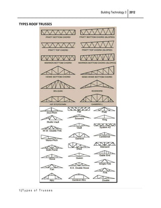
  • 1. Building Technology 3 2012 TYPES ROOF TRUSSES 1|Types of Trusses
  • 2. Building Technology 3 2012 Types • While many different trusses are available for roof construction, they can usually be broken down into one of two basic categories. Flat trusses, known as parallel-chord or girders, are used to construct flat roofs. Pitched, or common, trusses are used to build sloped-roof structures. Hip, gambrel or bowstring designs are popular examples of common trusses. Identification • All types of trusses have the same basic components and structure. The name "truss" describes a triangular design, which may range from a simple individual triangle to a large number of interconnected units. The outside framing members are known as chords, while the smaller connecting members are called webs. A point where the truss rests on a load-bearing wall is known as a bearing point, and a king post is a vertical support that divides the bottom chord on many types of trusses. Function • Roof trusses are used to carry and support the weight of the roof deck and any finish material used to cover the roof. This weight can be quite significant if clay or slate roof tiles are used, or it may be very light when used to support asphalt shingles or rolled roofing. The chords support the roof while the webs brace and stabilize the chords, helping to distribute the load across the entire truss to the bearing walls on either side. Benefits • One of the primary benefits to truss construction is the ability to span much longer areas than with traditional stick framing. Because trusses are designed by engineers, they are also safer and more reliable than alternative materials. Truss roof systems can be erected much more quickly and efficiently than framed roofs, and a variety of different truss designs are available offer versatility to builders and homeowners. Drawbacks • Because of the triangular shape of a truss, homeowners will find that roof trusses can greatly reduce the amount of usable space in the attic. This can cause problems with storage, or may even cut into potential living space. Trusses are also generally more expensive than stick framing in terms of upfront cost, though the associated labor savings may offset this higher material cost. • Common Trusses • A common roof truss is used to build a gable roof. In this system, two members called top chords slope up from the eave line and meet at the roof peak; the roof sheathing is attached to these chords. A bottom chord stretches horizontally between the top chords at the eave line. The 2|Types of Trusses
  • 3. Building Technology 3 2012 points where the bottom chord meets the top chord are where the truss rests on bearing walls and transfers the weight of the roof to the walls. A vertical king post rests on the bottom chord and supports the peak of the truss, and a web system of short members helps to transfer the load from the top chords to the bottom chord. Scissor Trusses • A scissor truss is similar to a common truss, but in this design two bottom chords slope upward from the eave line to the king post. In a common truss, the bottom chord functions as a horizontal ceiling joist for the room below, while in a scissor truss, the slope of the bottom chords form a cathedral ceiling. Other variations on the common truss can be used to form a studio or tray ceiling. Raised Heel Trusses • A raised heel truss offers both structural stability and room for more insulation, which helps to increase a home's energy efficiency. The design raises and separates the top chord from the bottom chord to produce extra space at the eaves. The net effect is an added extension to the top of the exterior wall, allowing for the full depth of insulation to be applied in key areas above the ceiling. Dropped Chord Trusses • Dropped chord trusses are constructed with a secondary chord added below the bottom chord. The additional truss prevents the ceiling from gradually bending upwards, and provides extra space for full-depth insulation within the outer walls. The secondary chord also helps to create an airtight vapor barrier. Dropped chord trusses offer several technical advantages, but also suffer from financial disadvantages due to the added cost of installing taller studs, more blocking and more siding. Scissor Roof Trusses • Scissor trusses have their lower chords pointed upwards so that the lower chord resembles an arrow that is pointing upwards, with the tip of the arrow intersecting below the upper chord. The advantage of this design is that it allows space beneath the roof for constructing a cathedral ceiling. This design also helps eliminate the necessity of a load bearing wall in the center of the structure. The sloped ceiling coupled with the limited space can make it difficult to install insulation when working on this type of trusses. Parallel Chord Trusses • Parallel chord roof trusses, or flat trusses, are constructed with two chords running parallel to each other and supported by reinforcing trusses in between the top and bottom chords. The biggest advantage of this type of design is that it provides space for easy installation of generous amounts of insulation. Among the disadvantages of using this type of design are increased costs due to the additional steel braces and the difficulty of insulating the space between chords. Attic Trusses 3|Types of Trusses
  • 4. Building Technology 3 2012 • Attic trusses are designed to provide an inexpensive way of creating additional storage space in a new home. Attic trusses resemble conventional "common trusses," but leave an empty space in the center to accommodate an extra room. Reinforcing trusses are placed on both sides, and above the room constructed in the center of the trusses. Attic trusses can provide more living or storage space, but will cost more to construct. Bowstring Trusses • Bowstring trusses, or Belfast trusses, are similar to conventional "common trusses" except for the top chord, which is constructed in a parabolic design. Bowstring trusses resemble the arched shape of an archery bow. The curved top chord and the horizontal bottom chord intersect each other at both ends. Bowstring trusses are designed to span large distances, such as those required for the roof of an aircraft hanger or warehouse. Gambrel Trusses • Gambrel trusses are constructed symmetrically with four slopes on the top chord. Two slopes are placed on each side with the lower slopes positioned at a steep angle and the upper slopes relatively flat. Gambrel trusses provide more room below the center of the trusses since the limited framing in the middle of the trusses increases floor space. Extra flat space for windows and skylights is also created by constructing the bottom chords at a steep angle. Types of Steel Trusses Steel trusses are built on exactly the same principles as wooden trusses, and any truss that can be built of wood can also be built of steel, but owing to the different nature of the two materials, the types of trusses best adapted to wooden construction are not the most economical for steel. Steel trusses are generally built of angles, channels, plates and eye bars, and as any of these shapes are better adapted to resisting a tensile stress rather than a compressive stress, economy requires that the form of the truss or arrangement of the members, shall be such that there shall be as few members in compression as practicable, and that the shorter web members shall be in compression and the longer ones in tension. Almost any combination of triangles can be made to support a roof, when built of steel, but some combinations will require a much greater weight of metal, to support the given load than others. Steel roof trusses having a span of less than 100 feet can generally be built more cheaply with riveted connections, or joints, and most of the arched trusses for wide spans, are also riveted together. For some types of trusses, however, the pin connection may be cheaper or more advisable construction. Pin connected trusses may be more conveniently shipped, and where they are supported by brickwalls, may sometimes be more economically erected. 4|Types of Trusses
  • 5. Building Technology 3 2012 Riveted trusses are almost always built of angles for the ties, and of a pair of angles or channels for the struts, the angles often being reinforced by a web plate. In pin-connected trusses eye bars are generally used for the ties, and a pair of channels, latticed or reinforced by plates for the struts. Number Of Struts Or Panels The best form for a steel truss, and the most economical number of braces will depend in a great measure upon the inclination and construction of the roof, as well as upon the span. If purlins are used to support the jack rafters then the distance between the struts may be as great as 12 feet, but if there are no jack rafters and the planking of the roof is nailed directly to the purlins, then the latter should not be placed more than 8 feet apart, and if the roof is covered with corrugated iron secured to the purlins, then the purlins can not be more than 5 feet on centres. Whenever the purlins are more than 4 feet apart, they should come over the end of a strut or brace, to avoid bending moments, consequently the spacing of the purlins will generally determine the number of struts in each half of the truss. For this reason the same form of truss may be required for a span of 40 feet as for a span of 80 feet, but, of course, the members will not be as heavy in the forty-foot truss as in the one with greater span. When the truss rafter is subject to a transverse strain, that is, when it is loaded between the joints, the distance between the joints should not exceed 9 feet and preferably 7 or 8 feet, depending somewhat on the distance the trusses are apart. Fig. 64. Trusses For Pitch Roofs For ordinary conditions and for spans less than 100 feet some one of the types shown by Figs. 64 to 75, will generally meet the requirements of strength and economy. For a narrow shed or shop the shape of truss shown by Fig. 64 is the most economical, the truss proper being that portion enclosed within the points A, B, C. This truss is practically the same as that shown by Fig. 65. 5|Types of Trusses
  • 6. Building Technology 3 2012 For spans of from 24 to 48 feet, and with an inclination not exceeding 6" to the foot, types 66 and 67 are the most suitable. The truss type represented by these two figures has received the name of "Fan truss." The truss shown by Fig. 65 is known as a "simple Fink truss." The truss shown by Fig. 67 differs from that in 66, principally in the inclination of the braces. The braces A, B, in Fig. 67 being inserted to brace the truss from the column to prevent racking under wind pressure. Fig. 67 should be used when the truss is supported by columns, and Fig. 66 when the truss rests on brickwalls. When the roof construction demands three purlins on each side of the truss, one of the forms shown by Figs. 68, 69, 70 or 71 should be used. Fig. 66. - Simple Fink Truss; Span, 20 to 36 ft. Fig. 66. - Simple Fan Truss. Fig. 67. - Fan Truss; Span, 40 to 50 ft. The names given to these trusses are often confounded by different writers; many engineers class the French and Fan trusses with the Fink truss. The term "French" appears to be generally given to those trusses in which the tie-beam is raised in the centre. The truss shown by Fig. 71, appears to have no generally recognized name. One writer refers to it as an "English" truss. This 6|Types of Trusses
  • 7. Building Technology 3 2012 truss is not as economical as the Fink truss, except when the inclination of the rafter is less than one-fourth pitch, on account of the great length of the inner struts. Fig. 68. - Compound Fink Truss. Fig. 69. - Eight-PanelFrench Truss. Although Fig. 71 somewhat resembles the Queen truss, Fig. 12, it will be seen that the diagonals run in the opposite direction, the diagonals in Fig. 71 being in tension, and the verticals in compression, the reverse of the Queen truss. Much of the economy of Fink and Fan trusses lies in the fact that most of the members are in tension and the struts are short. Comparing Figs. 70 and 71, it will be noticed that the inner strut in the former is only 1/3 as long as the strut in the latter. Another advantage of these trusses is that a partial load, as, for instance, a wind or snow load on one side of the truss never causes stresses in excess of those produced by a uniform load of the same intensity over the whole truss. As a general rule, the struts in Fink trusses are placed at right angles to the rafters, as in Figs. 68, 72 and 73, but if there are trussed purlins it is desirable to have vertical members to receive the ends of the purlins. Vertical struts are generally required in hip trusses. Fig. 70. - Fink Truss with Vertical Struts. 7|Types of Trusses
  • 8. Building Technology 3 2012 Fig. 71. English Truss Depth Of Fink And Fan Trusses The depth of these trusses at the centre is usually determined by the roofing material that is to be used. Thus, slate should not be used on a roof in which the rise is not equal to one-thirdof the span; the rise for wood shingles should not be less than one-fourth of the span, and for corrugated iron not less than one-fifth of the span. Fig. 72. - Ten-Panel Fink Truss. Fig. 73. - Twelve-Panel Fink Truss. Considering the construction of the roof and the weight of the trusses, the most economical pitch for a roof is about 1/4 the span, or what is commonly called a quarter pitch, the rise of the rafters being 6" in 12" or 26 degrees and 34 minutes. When the rise is less than 1/6 of the span some other type of truss will generally be required. When the inclination of the roof is determined almost entirely by the question of economy the rise is generally made from 6 to 7 inches in 12 inches. 8|Types of Trusses
  • 9. Building Technology 3 2012 Cambered Trusses With Fink or Fan trusses having an inclination for the rafter not exceeding 30 degrees it is more economical to employ a horizontal chord or tie since it obviates bending of the laterals. Raising the bottom chord, also materially increases the strains in the truss members, hence it increases the cost. A truss whose bottom chord has a rise of two or three feet, as in Fig. 69, presents a better appearance, however, than one with a horizontal chord, and for steep roofs, it will generally be fully as economical to raise the bottom chord because of the shortening of the members. Trusses with raised ties are designated as "Cambered." Fig. 74. - French Truss with Vertical Struts. Span, 80 ft. 33. The diagram shown by Fig. 75 represents 1/2 of one of the steel trusses used in roofing a car barn for the North Jersey Railway Co., atNewark, N. J. There were 13 of these trusses, spaced 19' 2 1/4" on centres, each having a span of 98 1/4' between the centres of the supporting columnsto which the truss is riveted by splice plates engaging the end connection plate and the end web of the column. The dimensions of the principal members of these trusses are indicated in connection with the illustration. These trusses were shipped in four sections which were assembled in a horizontal plane and riveted up complete at the surface of the ground. The bottom chord was stiffened by lashing a rail on each side of it for its entire length and a sling being attached to the apex of the top chord, the truss was lifted and set on top of the columns by an 8" x 8" gin-pole 50 feet high. The roofing consists of corrugated iron supported by 5" I-beam purlins weighing 10 lbs. to the foot, spanning from truss to truss and bolted to the rafters with two bolts at each end; the general spacing of the purlins being 4' 9 3/4". This may be considered as an example of an extremely light roof, the weight of each truss being only about 4,200 lbs., and the entire weight of the truss, purlins, bracing of the lower chord and corrugated roofing being only 8 lbs. for each horizontal foot of surface covered. The truss shown by Fig. 74 was designed for the roof of a drill hall having a span of 80' and with a spacing, centre to centre, of 20'. The roof was to be constructed with 2x8 rafters supported by purlins at points A, B, C, D, E, and F. Sash were to be placed in the rise C D to light the interior of the building. The joint at X was located with reference to the 9|Types of Trusses
  • 10. Building Technology 3 2012 position of the gallery rod; if there had been no gallery it would have been more economical to space the vertical struts uniformly as in Fig. 70. Dimensions of Members in Fig. 75. Rafters.. 1 - 2 = 2 - 5" x 3 1/2" x 7/16" L's. Rafters.. 2 - 3 = 2 - 5" x 3 1/2" x 3/8" L's. Main tie.. 1 - 4 = 2 - 5" x 3 1/2" x 3/8" L's. Main tie.. 4 - 5 = 2 - 3 1/2" x 2 1/2 x 5/16" L's. a, a, a....... = 2 - 2 1/2" x 2" x 1/4" L's. b, b, b....... = 1 - 2 1/2" x 2" x 1/4" L. = 2 - 3" x 2 1/2" x 1/4" L's. = 2 - 3 1/2" x 2 /2" x 5/16" L's. Fig. 75. - Diagram of Compound Fan Truss. 10 | T y p e s o f T r u s s e s
  • 11. Building Technology 3 2012 Fig. 7G. - Warren Triangular Truss. Fig. 77. For roofs having a span of 80 to 100 feet, and a rise of from one-fourth to one-thirdof the span, the Warren triangular truss shown by Fig. 76 is a good type. This truss is best adapted to pin connections. For a steep roof, the type shown by Fig. 77 is about as economical as any. A complete example of this type of truss with the details of the computations is given in Part II., of Berg's "Safe Building." The plus sign adjacent to a member, in all the trusses illustrated, denotes that the member is in compression, while the minus sign denotes tension. In Figs. 76 and 77 the members represented by single lines are in tension. The members above the main rafter as C D, D E, and E F, in Fig. 74, and a and b in Fig. 75 do not form a part of the truss proper but are merely a frame work to support the elevated roof and in drawing the stress diagram, they should be omitted 34. FINK TRUSSES WITH PIN JOINTS. - Fig. 78 shows one-half of a Fink truss designed for pin connections. This truss has a span of 55' 4" between centres of end pins and the distance between the centres of trusses is 6'. The roof is covered with 12" x 20"slate, secured to 1 1/2 x 2 1/4" angle purlins weighing 3 lbs. to the foot and spaced 8 1/2" on centres. The angles span from truss to truss and are bolted to the deck beam with 1/2" bolts. A 1 1/2" by 2 1/4"nailingstrip is fastened to every third purlin for securing matched ceiling placed on the underside of the roof. Complete details of this truss were published in "Architecture and Building" for January 18, 1890. Fig. 79 shows details of the cast-iron struts. This truss, being put together entirely with bolts and pins, could easily be erected with unskilled labor. 35. TRUSSES FOR FLAT ROOFS. - For supporting flat roofs or roofs having a fall not exceeding 1" to the foot, one of the types shown by Figs. 80 to 84 will generally be found economical. The choice of the particular type depending somewhat on the span and whether the truss is supported by columns or by brick or stone walls. For spans up to 50' either of the forms shown by Figs. 11 | T y p e s o f T r u s s e s
  • 12. Building Technology 3 2012 Fig. 78. - Fink Truss with Pin Connections, lower chord between the end joint and the wall, Fig. 80, has no stress from the roof load but is put in to brace the wall, and to stay the truss. In trusses supported by brick walls this type is preferable to that shown by Fig. 81, while the latter is more suitable when the roof is supported by columns. The vertical A, Fig. 81, is in- 80 or 81 will answer all practical requirements. The truss shown by Fig. 80 is intended to be used where the fall of the roof is at right-angles to the truss; this truss can be built, however, with an inclination to the top chord as in Fig. 81. The end brace in Fig. 80 is in tension while in Fig. 81 it is in 12 | T y p e s o f T r u s s e s
  • 13. Building Technology 3 2012 compression. The portion of the inserted to receive the tension or compression from the brace B, and would have no stress from the roof load. The truss shown by Fig. 82, which represents an actual truss is known as a "Double Warren Truss" and is desirable where it is important to make the trusses as shallow as practicable; it can be built with light members and makes a very stiff roof, being especially suitable for roofs supported by steel columns. The strength of this truss under unsymmetrical loads, as, for example, when there is more snow on one side than on the other, would be materially increased by putting a vertical tie in the center as shown by the dotted line; without this member the braces AA, if subject to any stress whatever, would produce a bending in the bottom chord at the center. Fig. 83 represents an actual roof truss with a span of 57' supported by steel columns. The entire load on the truss is transmitted to the columns by the braces B, B, which are in tension. Fig. 84 shows a Warren truss of 96' span over a pier shed, New York City. Fig. 79. Details of Struts in Fig. 78. Fig. 80. - Span, 56 ft. 13 | T y p e s o f T r u s s e s
  • 14. Building Technology 3 2012 Fig. 81. - Span, 30 to 36 ft. Fig. 82.-Span. 50 ft. Fig. 83. - Span. 57 ft. Fig. 84. - Span, 96 ft. The plus and minus signs in these illustrations indicate compression and tension, respectively, under uniform dead load. The plus and minus sign together indicate that the member may be subject to either tension or compression, according to the direction of the wind or to an uneven distribution of snow. In most of these trusses an unsymmetrical load may change the stress in the diagonals neat the centre of the truss. Trusses like those shown by Figs. 80-84 are almost invariably built with riveted connections and with angle or channel shapes for all members. For Horizontal Steel Trusses Intended to Support Floor Loads, the Pratt truss shown by Figs. 85 and 86 is best adapted, the members indicated by double lines being in compression, and those indicated by single lines in tension. When supporting floors subject to moving loads, counter ties should be inserted as indicated by dotted lines. For this truss, pin connections are generally 14 | T y p e s o f T r u s s e s
  • 15. Building Technology 3 2012 employed and are preferable to riveted connections. When properly proportioned this truss is capable of sustaining almost any load. Fig. 85. - Pratt Truss; Span, 60 to 150 ft. Fig. 86. - Suspended Pratt Truss; Span, 40 to 80 ft. The Quadrangular Truss The truss shown by Fig. 83 is known as a quadrangular truss, although the more common shape for this truss is that shown by Fig. 87. This truss may be considered as two trussed rafters, held in place by the tie T at the centre. The portions of the truss which are in compression are indicated by double lines while the single lines represent the tension members. The dotted lines represent counter-braces or ties, which might be brought into action in case of a heavy snow load on one side only or during a severe gale. The piece B has no strain when the truss is subjected only to a vertical load, although it is usually put in to brace the post P, which carries the entire load transmitted to the support. This truss is well adapted to steel construction up to spans of 180 feet. When the span exceeds 100 feet, and the truss rests on a brickwall one end of the truss should be supported on rollers to allow for expansion and contraction in the steel. The proportions of the truss shown in Fig. 87 are those of the roof trusses of the Jersey City-station of the Central Railroad of New Jersey. The trusses in this building have a span of 142 feet 4 inches, centre to centre of bearings, with a depth in the centre of 24 feet 4 inches. The distance between trusses is 32 feet 6 inches. The joints are pinconnected, eye-bars being used for the tension members, and one end of the truss is on rollers. Fig. 88 gives the proportions of similar trusses over the amphitheatre of the Madison Square Garden, New York.* In both of these trusses the posts and braces at the ends are made a part of the truss, although they cannot be represented in the strain diagram, and the post P receives the whole load from the truss at its upper end, the diagonal tie transmitting the entire web stress to the top of the post. The brace B should be so constructed as to resist both tension and compression. This truss, like the other, is pin-connected, with eye-bars for the tension members. The principal dimensions of the truss are given in the drawing. 15 | T y p e s o f T r u s s e s
  • 16. Building Technology 3 2012 Fig. 87. - Typical Quadrangular Truss. Fig. 88. - Truss over Amphitheatre; Madison Square Garden. * Details of these trusses were published in 'Architecture and Building" for April 21, 1890. Fig. 89 shows another exampl eof this type of truss with intermediate supports for the purlins. The truss shown by Fig. 90 also belongs to this type, but differs from the trusses shown by Figs. 87-89, in that the diagonals are all in the same direction. This causes a reversal of the stresses in the web members, as indicated by the plus and minus signs, the three diagonals at each side of the centre being in compression and the adjacent uprights in tension. In the trusses shown by Figs. 87-89, all of the diagonals are in tension and all the verticals in compression. The truss proper, is included within the figure A, B, C, E, D. 16 | T y p e s o f T r u s s e s
  • 17. Building Technology 3 2012 Fig. 89. - Span, 102 ft. Fig. 90. - Quadrangular Truss; Span, 80 ft. It may be noticed that the lower chord of these trusses is segmental in shape, giving a graceful outline, and also the most economical proportions for wide spans. For shorter spans a full semicircle or semi-ellipse may be obtained by giving a greater curve to the lower chord and continuing it by means of braces. Fig. 91 shows how this was accomplished in the roof trusses over the wings of the Manufacturers' and Liberal Arts Building of the World's Columbian Exposition at Chicago. The parts included between the joints A, B, C, D form a quadrangular truss, while the portions X, X are merely braces external to the truss. 17 | T y p e s o f T r u s s e s
  • 18. Building Technology 3 2012 Fig. 91. The trusses supporting the central roof of the Mining Building, represented in Fig. 111, are also of the same type; although in this building the lower chord and braces have the form of a semiellipse. In both of these figures the tension members are represented by single lines. All the members in this truss were made of angles, so as to take up either tension or compression, and the joints were riveted. The stresses in quadrangular trusses due to wind and snow should be determined independently of the dead load, and the members computed for the maximum stress that may be produced by any possible combination of loading. There are numerous examples in this country of quadrangular trusses of from 100 to 180 feet span. The truss shown by Fig. 92, which is a diagram of one of the trusses over the Kansas City Auditorium, may be considered as a cross between the Warren truss and the Quadrangular truss, for if the end panels were omitted the truss would be almost identical in shape to that shown by Fig. 90. This truss has pin connections at the joints. The three diagonals each side of the centre are formed by lattice channels, and all of the ties are formed by eye-bars. The plus sign denotes compression and the minus sign tension. The diagram below the truss drawing shows the manner in which the trusses were braced laterally. All measurements are from centre of pins. A description of this truss and of the building may be found in the "Engineering Record" for July 22, 1899. Arched Trusses For open roofs of wide span arched trusses are generally the most economical, and as a rule give the most pleasing appearance. The economy of an arched truss lies in the fact that the principal compression members follow approximately the line of greatest strain, so that the bracing can be made very light. Thus, if the frame shown in Fig. 93 is so built that the joints come in the line of a parabola with the lower ends secured by a horizontal tie, and all the joints are uniformly loaded, the frame will remain in equilibrium without bracing. In practice perfect equality of loads cannot be maintained, and the 18 | T y p e s o f T r u s s e s
  • 19. Building Technology 3 2012 weight of the tie must also be supported from the upper chord, so that to make a practical truss it is necessary to introduce bracing between the arched rib and the tie, either as shown in Fig. 94 or Fig. 95. Fig. 92. - Elevation of Truss and Plan of TwoTrussesShowing Lateral Bracing. The braces provide for the inequality of the loads, and the tension members take up the thrust in the braces. The effect of the inequality of the loads, however, is usually such that only very slight strains are brought upon the bracing, so that the amount of material required for a truss of this shape is considerably less than in a truss with a straight rafter. That the framework shown in Fig. 93 shall be in equilibrium, the joints must be in the curve of a parabola, but as bracing is always necessary, the upper chord may have the form of the arc of a circle without greatly increasing the strains in the bracing. Fig. 93. Trusses of the types shown in Figs. 94 and 95 have been more extensively used for bridges than for roofs, as they are not so well adapted to the usual conditions of roof construction. For a segmental or parabolic roof, however, this type makes a very economical truss. 19 | T y p e s o f T r u s s e s
  • 20. Building Technology 3 2012 In the truss shown by Fig. 94, the vertical pieces B, C and D are in compression when the load is applied at the top, and the vertical member A has no strain except the weight of the tie-rod. If the loads are applied at the bottom all the members of the truss except the curved rafter will be in tension. Fig. 94. Fig. 95. With the bracing arranged as shown in Fig. 95, the diagonals are always in compression under a vertical load; the centre vertical has no strain except such as comes from the tie-beam and its load. The arrangement of the bracing shown in Fig. 95 is the best for a wooden truss. The arch form in roof trusses is used principally in the types known as: A. Bowstring and Crescent Trusses. B. Segmental Arched Ribs. C. Braced Arches. Bowstring Trusses Although the trusses shown by Figs. 94 and 95 are known as bowstring trusses, the usual type of the bowstring truss is that shown by Fig. 96. In this truss all of the members except the upper chord are in tension, and the strains in the bracing are comparatively slight, thus making it a very economical truss for steel construction. For trusses having a span of 75 feet or less the suspending pieces should be radials, but in trusses of larger spans they may be vertical, as in Fig. 97. 20 | T y p e s o f T r u s s e s
  • 21. Building Technology 3 2012 Fig. 96. Bowstring trusses of the form shown in Fig. 97 have been much used in England and to a considerable extent in this country. The upper chord is usually bent to the arc of a circle, with a rise in the centre of from one-fifth to one-third of the span. The depth of the truss in the centre should be about one-half of the rise. Fig. 97. There are numerous examples of wrought iron bowstring roof trusses of from 120 to 211 feet span, principally in the roofs of train sheds. A truss of the shape shown in Fig. 97, with a span of 212 feet, a total rise of 40 feet 6 inches and a depth in the centre of 23 ft. 6 ins., was constructed with a 15-inch I-beam for the upper chord and a 4-inch round rod, in short lengths, for the lower chord. The diagonals were made of flat bars and the vertical pieces of cross-shaped bars to give stiffness to the truss, although these pieces are subject to a tensile strain. For a straight-pitch roof of moderate span there is no economy in using this type of truss, as the extra cost of the necessary framework above the truss for supporting the purlins will offset the saving in the truss itself. Of late years the bowstring truss has been but little used in this country, engineers and architects seeming to prefer the braced arch instead. 21 | T y p e s o f T r u s s e s
  • 22. Building Technology 3 2012 Fig. 98. The Crescent truss has been described in Section 25, Chapter I (Foundations On Firm Soils. Staking Out The Building). It is seldom used, except for the support of dome roofs, for which examples are given in Chapter V (Building Stones). Segmental Arched Ribs Fig. 98, which is a diagram of one of three arches used in roofing the train shed of the Sullivan Square station of the Boston Elevated Railway, is a good example of this type. This construction is the same in principle as that of the wooden arch shown by Fig. 59; it can hardly be considered as a truss in the ordinary meaning of the word, although it is a perfectly legitimate form of construction. The arches over the Sullivan Square station spring from steel columns and are provided with tension rods which take up the thrust. The arch proper rests on two 4 1/4" pins at each end as indicated in - the diagram, the tie-rods being connected to these pins. The bracing below the pins is riveted to the column and the arch itself is built of angles and plates with riveted connections. Fig. 98A shows the joint at A, where the tie-rods are connected and are held up by a l" suspension rod from the crown of the arch. A more complete description of this truss is given in the "Engineering Record" of June 15, 1901. 22 | T y p e s o f T r u s s e s
  • 23. Building Technology 3 2012 Three-Hinged Braced Arches This truss differs from all the other types of trusses that we have considered in that it consists essentially of two separate parts, each acting as a single piece and depending upon the opposing force of its mate to keep it in position. As usually built, each part is a semi-braced arch, the upper and lower members being so connected by bracing as to form a stiff frame or curved rafter. The first use of the braced arch appears to have been in building railway bridges for French railroads, the earlier forms being rigidly connected at the top. The first suggestion for hinging the ribs at the crown was made by M. Manton, a French engineer, who, in 1861, suggested the type of arched truss shown in Fig. 99. It is evident that the fundamental principle of this truss is the same as that of therooftrusses shown in Figs. 100 to 102. The first applicationof this principle to roof trusses, at least on a large scale, the author believes to have been in the train sheds of a Union Railway station at Frankfort-on-the Main, Germany, which was completed in the year 1888. These trusses have a span of about 184 feet. The large roof of Machinery Hall, of the Paris Exposition of 1889, was supported by this type of truss, the span in this case being 368 feet, exceeding anything hitherto attempted in a roof truss. The use of this truss in the Manufacturers and Liberal Arts Building of the Columbian Exposition made the type familiar to most of the architects of this country, and it has since been extensively used for roofing exposition buildings, armories, train sheds, etc. Fig. 98A. In all of these trusses the arched ribs are supported at the bottom on a turnedsteelpin, and with the exception of the Frankfort truss all abut against a pin at the top, thus giving the name - ThreeHinged Arch. 23 | T y p e s o f T r u s s e s
  • 24. Building Technology 3 2012 Fig. 99. Usually the trusses are surmounted by a lantern, as shown in Figs. 101 and 102, which are bolted or riveted together at the centre. With the shape of ribs generally used there is always a slight outward thrust at the bottom, which must be resisted either by the abutments, as in Fig. 99, or by tie-bars connecting the lower pins. Most of the trusses erected in this country have tie-bars placed just beneath the floor, but the trusses in the Frankfort Depot and Machinery Hall, Paris, had no ties, and Messrs. D. H. Burnham & Co. used three-hinged archesof 160 feet span in the First Regiment Armory, Chicago, which support two floors and a gallery, besides the roof, without ties. Fig. 100. - Half-Truss, Machinery Hall, Paris Exposition, 1889. The special advantages of this type of truss for the class of buildings above mentioned are economy, maximum clear space beneath the truss and provision for expansion and contraction. Much of the economy of the truss lies in the fact that it requires no columns to support it, and, the base of the truss being very near the ground level, it is well proportioned to resist wind 24 | T y p e s o f T r u s s e s
  • 25. Building Technology 3 2012 pressure. A great advantage of this truss is the free movement allowed under temperature changes without strain to the structure, the centre rising or falling freely with a slight rotation of the semi-arches about the pivots. In the case of the trusses of the Paris Exposition it was estimated that a range of temperature of 100° F would produce a change in level of 2 7/8 inches at the centre pivot. Fig. 101. - Half-Truss, Manufacturers' and Liberal Arts Building, Chicago, 1893. The arched ribs are always built of plates and angles with riveted connections, and frequently with a solid plate web at the bottom. The determining of the stresses and detailing of the members and joints will require the service of a competent structural engineer, but the illustrations given will enable the architect to decide 25 | T y p e s o f T r u s s e s
  • 26. Building Technology 3 2012 on the general shape of the truss for the purpose of making preliminary drawings and the computations and detail drawings can be made later. Fig. 102. - From Machinery Hall, Chicago, 1893. 41. The trusses in the Liberal Arts Building and in Machinery Hall at Chicago were spaced about 50 feet apart from centres. In the Liberal Arts truss the inner rib is bent to a curve up to the joint A, and above that it is made up of straight pieces.* Similar trusses are also used over the train sheds of the Pennsylvania Railroad station and the Reading Railroad station in Philadelphia. The trusses of the former building have a span between pins of 300 feet 8 inches, a rise of 108.49 feet, with a depth at the springing of 5 feet 3 inches. The lower pins are 5 1/2 inches in diameter.† The trusses in the Reading Railroad Depot have a span of 260 feet. The roof of the Central Armory, Cleveland, O., Messrs. Lehman & Schmitt, architects, is supported by six three-hinged plate-girder arches, that is, with a solid web instead of bracing. This is the only instance of a solid web in large arches with which the writer is acquainted, and it would appear as though it might be advantageously employed in many instances. The trusses in the Cleveland Armory have a span of 120 feet and a rise of 52 feet 6 inches, centre to centre of pins. The two end arches also support a gallery as well as the roof. Complete details of these trusses are published in the "Engineering Record" of December 26, 1896. 26 | T y p e s o f T r u s s e s
  • 27. Building Technology 3 2012 Fig. 103. Braced Arches Without Hinged Joints For spans of from 80 to 120 feet this type is often built without the pin connections as in Fig. 103. The mechanical principle being essentially the same as in the three-hinged truss. Cantilever Trusses The term "cantilever" was originally used to designate a projecting beam which served as a bracket; in mechanics it is used to denote a beam or girder fixed at one end, either by being built into a wall, or, most commonly, by extending a sufficient distance beyond its support to form an anchorage for the cantilever. Thus, in Fig. 104, we have a beam resting on two supports; the portion B is a cantilever, while the part C forms the anchorage for it. [In applying the term cantilever to trusses it is customary to interpret it as including both the projecting arm and the balancing arm, as both portions form one piece of framework, and the term will. be so used in this work.] 27 | T y p e s o f T r u s s e s
  • 28. Building Technology 3 2012 Fig. 104. Fig. 105. Fig. 106. Fig. 107. Fig. 108. It is obvious that if the entire beam (Fig. 104) were uniformly loaded the post P would carry the greater part of the weight, and also that an additional load at W might produce an upward pull on the post D, in which case the stress on P would exceed the load on the beam. 28 | T y p e s o f T r u s s e s
  • 29. Building Technology 3 2012 Both conditions of loading occur in practice, although it probably most often happens that the outer end of the truss requires anchorage rather than a support. As applied to roof construction some such arrangement as is shown in Fig. 105 is generally required to make this method of support practicable; that is, a wide centre span, with shorter spans or aisles on each side of it. The projecting or inner arm of the cantilever is usually made from one-quarter to one-third of the centre span, and a simple truss, represented by S, is used to support the balance of the roof, the centre truss being supported by the arms of the cantilever. In all such cases, therefore, cantilever trusses must be used in pairs, one on each side of the building, and there must be rooms or passages outside of the principal span to permit of the outer or balancing arm. Such an arrangement is generally found in large halls, armories, exhibition buildings, etc., and it might sometimes be provided in other classes of buildings. Of course, in a large building a simple beam such as is shown in Fig. 105 could not be used, but the principle of construction is the same, whether the cantilever be a simple beam or a large truss. Pig. 109. - Suggestion for Wooden Cantilever Truss. Fig. 106 shows the diagram for a truss to take the place of the beam C B, Fig. 105, the single lines representing the tension members and the double lines compression members, and Fig. 109 shows the complete arrangement of the trusses.* The truss shown in these figures may be extended to almost any extent, and the form of the lower chord may be changed, but the general outline of the truss will be found best adapted for all cases where a wide central roof is to be supported by cantilevers. For bridge trusses or floors the shape shown in Fig. 107 may be used, and for shed and platform roofs open on one side a truss of the shape shown in Fig. 108 is about the only practicable device. In this latter truss the proportions of the arms are such that a slight support is required at W, thereby bringing the lower portion of the rafter into compression. 29 | T y p e s o f T r u s s e s
  • 30. Building Technology 3 2012 It will be seen from Figs. 106-108 that the strains in a cantilever truss are directly the reverse of those in trusses supported at both ends, the upper chord or rafter in the cantilever being in tension, while in all other trusses, except the hinged arch, it is in compression. 44. Advantages And Disadvantages Of The Cantilever Truss The special advantages possessed by the cantilever truss are: a greater clear height in the centre than can be obtained with any other type (excepting the three-hinged arch), a light and graceful appearance, no horizontal thrust, and consequently no tie-rods required. The particular advantage of this truss for very great spans is that it can be erected without scaffolding under the centre, and in bridge work this is considered as its only advantage. Fig. 110. - Cantilever Truss, Agricultural Hall, Norwich, England. It is claimed by prominent engineers that the cantilever is not an economical type of truss, and not as desirable for spans of 150 feet or more as the three-hinged arch. It also does not permit of as readily overcoming expansion and contraction as either the threehinged arch, the bowstring truss or the quadrangular truss. For certain classes of buildings, however, and especially where the central span does not exceed 150 feet, it can perhaps be used with better architectural effect than is possible with other types, and with about the same economy. For roofing platforms, grand stands, etc., where an outer support is not desired, it is the only type of truss available. 30 | T y p e s o f T r u s s e s
  • 31. Building Technology 3 2012 45. Examples Of Cantilever Roof Construction There are few examples of cantilever roof trusses of constructional importance, although there are many examples of cantilever bridge trusses. Fig. no shows the proportions and some of the details of the roof trusses of the Agricultural Hall, Norwich, Eng. By using curved ribs for the compression members the truss is given a very light and graceful appearance, and it would appear to contain a minimum amount of material. Fig. 111. - Cantilever Truss, Mining Building, Chicago, 1893. The portion of the arch between the points A and B was probably put in to preserve the arch effect, as it could have been dispensed with. Fig. III shows the proportions of the cantilever trusses used in the Mining Building at the Columbian Exposition; the double lines represent the compression members (with the exception of the arched chord of the outer span, which is in tension) and the single lines the tension members. The cantilever portion of the truss is included between the points F, B, C, D, and the anchorage truss between the points A, F, D. The curved ribs, E, E, E, do not enter the stress diagram, but merely serve as stay braces and in carrying out the arched effect. In this roof the anchorage arm more than balances the cantilever and its load, and hence exerts a vertical load upon the outer support. The distance between trusses was 64 feet 5 5/16 inches. Mr. E. C. Shankland, the engineer in charge of the constructional work of theExposition buildings, says of this truss: "They are interesting as adding another type to the variety of trusses in the park, although they are not at all economical." The truss as built was noticeably heavy. The lantern truss is a separate quadrangular truss supported by the cantilevers at the points C and P. Provision for expansion and contraction in this roof was made by means of a 5 1/2-inch slotted hole at the joint P, thus permitting a lateral movement of the 3-inch pin of 2 1/2 inches. 31 | T y p e s o f T r u s s e s
  • 32. Building Technology 3 2012 The cantilever trusses have pin-connected joints and the quadrangular truss riveted joints.* Fig. 112. Fig. 112 is a diagram of one of the cantilever trusses supporting the roof of the grand stand at the Monmouth Park (N. J.) racing track, the details of which were published in "Architecture and Building" in February, 1890. This is an instance where the cantilever was the only type of truss that could be used, and the form adopted is both simple and economical. As will be seen from the drawing, the main supporting post extends to the top of the truss, as is usually the case with cantilever trusses, and the truss is riveted to each side of it. The upper and lower chords were made of two angles and a web plate, the upper chords or rafters acting as a tie-beam between the bracing. The bracing consists of angle bars used in pairs and varying from 3 x 2 x inches to 3 x 3 x 5/16 inches, the whole frame being connected by rivets. *The details and stresses in these trusses were published in the "Engineering Record," Vol. XXIX., page 9. Layout Of Trussed Roofs - Bracing Of The Roof And Trusses 46. The general arrangement or layout of the roof construction should be considered when making the preliminary studies, as in buildings with trussed roofs the manner in which the roofs are to be supported affects both the cost and the appearance of the building, and often the internal arrangement. In deciding upon the "layout," the type of truss or trusses to be used, their approximate span and rise should be carefully considered and fixed, as upon these will often depend the shape of the ceiling, the arrangement of the supports and the height and pitch of the roof. If these factors have been wisely determined, the consideration of the strength and details of the construction may be left until the general plans are completed, as within certain limits of span and rise any truss may be made of sufficient strength and rigidity, and the size of the truss members does not, as a rule, affect the rest of the building. 32 | T y p e s o f T r u s s e s
  • 33. Building Technology 3 2012 When designing a trussed roof it should be remembered that short spans and a level tie are in general the most economical, and if the span can be reduced by using posts and without interfering with the internal arrangements it is better to do so. In roofing buildings having large rooms, with permanent walls between, advantage should always be taken of the walls by placing posts over them to support the purlins directly above. The principal points to be fixed inlaying out a trussed roof are: The type or types of trusses to be used, the pitch of the roof, the distance that the trusses shall be placed apart and the spacing of the purlins. As the settlement of these questions will be determined in a great measure by the character and style of the building and the purpose for which it is to be used, it seems best to take them up in connection with different classes of buildings, or forms of construction. ADVANTAGES OF STEEL TRUSSES • 100% non-combustible • Long clear-span capabilities • Limitless roof and ceiling profiles--just like wood trusses • Lightweight • Does not promote the growth or spread of mold • Pre-engineered and pre-fabricated by truss professionals • Reduce or eliminate attic sprinkling systems and other code requirements needed with combustable materials • Compatible with almost any decking/roofing system • Relieves design firms of costly, time consuming roof design work--frees them up for more productive endeavors • Provides point values toward "Green" buildings REFERENCES: http://chestofbooks.com/architecture/Construction-Superintendence/Chapter-II-Types-Of-SteelTrusses.html#ixzz20ySOLRb5 33 | T y p e s o f T r u s s e s
  • 34. Building Technology 3 2012 Types of Roof Trusses | eHow.com http://www.ehow.com/about_5456200_types-rooftrusses.html#ixzz20yQZjvrE 34 | T y p e s o f T r u s s e s