SlideShare a Scribd company logo
1 of 20
Download to read offline
The Babcock & Wilcox Company

Chapter 1
Steam Generation – An Overview

Steam generators, or boilers, use heat to convert
water into steam for a variety of applications. Primary
among these are electric power generation and industrial process heating. Steam is a key resource because
of its wide availability, advantageous properties and
nontoxic nature. Steam flow rates and operating conditions are the principal design considerations for any
steam generator and can vary dramatically: from 1000
lb/h (0.1 kg/s) in one process use to more than 10 million lb/h (1260 kg/s) in large electric power plants; from
about 14.7 psi (0.1013 MPa) and 212F (100C) in some
heating applications to more than 4500 psi (31.03 MPa)
and 1100F (593C) in advanced cycle power plants.
Fuel use and handling add to the complexity and
variety of steam generating systems. The fuels used
in most steam generators are coal, natural gas and oil.
However, nuclear energy also plays a major role in at
least the electric power generation area. Also, an increasing variety of biomass materials and process
byproducts have become heat sources for steam generation. These include peat, wood and wood wastes,
bagasse, straw, coffee grounds, corn husks, coal mine
wastes (culm), and waste heat from steelmaking furnaces. Even renewable energy sources, e.g., solar, are
being used to generate steam. The steam generating
process has also been adapted to incorporate functions
such as chemical recovery from paper pulping processes, volume reduction for municipal solid waste or
trash, and hazardous waste destruction.
Steam generators designed to accomplish these
tasks range from a small package boiler (Fig. 1) to
large, high capacity utility boilers used to generate
1300 MW of electricity (Fig. 2). The former is a factory-assembled, fully-automated, gas-fired boiler,
which can supply saturated steam for a large building, perhaps for a hospital. It arrives at the site with
all controls and equipment assembled. The large fielderected utility boiler will produce more than 10 million lb/h (1260 kg/s) steam at 3860 psi (26.62 MPa)
and 1010F (543C). Such a unit, or its companion
nuclear option (Fig. 3), is part of some of the most complex and demanding engineering systems in operation today. Other examples, illustrating the range of
combustion systems, are shown by the 750 t/d (680
tm/d) mass-fired refuse power boiler in Fig. 4 and the
circulating fluidized-bed combustion boiler in Fig. 5.
The central job of the boiler designer in any of these
Steam 41 / Steam Generation – An Overview

applications is to combine fundamental science, technology, empirical data, and practical experience to
produce a steam generating system that meets the
steam supply requirements in the most economical
package. Other factors in the design process include
fuel characteristics, environmental protection, thermal
efficiency, operations, maintenance and operating
costs, regulatory requirements, and local geographic
and weather conditions, among others. The design
process involves balancing these complex and sometimes competing factors. For example, the reduction
of pollutants such as nitrogen oxides (NOx) may require a larger boiler volume, increasing capital costs
and potentially increasing maintenance costs. Such
a design activity is firmly based upon the physical and
thermal sciences such as solid mechanics, thermodynamics, heat transfer, fluid mechanics and materials
science. However, the real world is so complex and
variable, and so interrelated, that it is only by applying the art of boiler design to combine science and
practice that the most economical and dependable
design can be achieved.
Steam generator design must also strive to address
in advance the many changes occurring in the world
to provide the best possible option. Fuel prices are
expected to escalate while fuel supplies become less
certain, thereby enforcing the need for continued efficiency improvement and fuel flexibility. Increased
environmental protection will drive improvements in
combustion to reduce NOx and in efficiency to reduce
carbon dioxide (CO2) emissions. Demand growth continues in many areas where steam generator load

Fig. 1 Small shop-assembled package boiler.

1-1
The Babcock & Wilcox Company
power plant thermal efficiency. Also, modularization
and further standardization will help reduce fabrication and erection schedules to meet more dynamic
capacity addition needs.

Steam generation fundamentals
Boiling
The process of boiling water to make steam is a familiar phenomenon. Thermodynamically, instead of
increasing the water temperature, the energy used
results in a change of phase from a liquid to a gaseous
state, i.e., water to steam. A steam generating system
should provide a continuous process for this conversion.
The simplest case for such a device is a kettle boiler
where a fixed quantity of water is heated (Fig. 6). The
applied heat raises the water temperature. Eventually, for the given pressure, the boiling (saturation)
temperature is reached and bubbles begin to form. As
heat continues to be applied, the temperature remains
constant, and steam escapes from the water surface.
If the steam is continuously removed from the vessel,
the temperature will remain constant until all of the
water is evaporated. At this point, heat addition would
increase the temperature of the kettle and of any
steam remaining in the vessel. To provide a continuous process, all that is needed is a regulated supply of
water to the vessel to equal the steam being generated and removed.
Technical and economic factors indicate that the most
effective way to produce high pressure steam is to heat
relatively small diameter tubes containing a continuous
flow of water. Regardless of whether the energy source
is nuclear or fossil fuel, two distinct boiling systems are

Fig. 2 1300 MW coal-fired utility steam generator.

may have to cycle up and down more frequently and
at a faster rate.
There are technologies such as pressurized fluidized-bed combustion and integrated gasification combined cycle systems, plus others, which actually integrate the environmental control with the entire steam
generation process to reduce emissions and increase

Fig. 3 900 MW nuclear power system.

1-2

Fig. 4 Babcock & Wilcox 750 ton per day mass-fired refuse power
boiler.

Steam 41 / Steam Generation – An Overview
The Babcock & Wilcox Company
used to accomplish this task: those that include a steam
drum (see Fig. 7a), or fixed steam-water separation point,
and those that do not (see Fig. 7b), termed once-through
steam generators (OTSG).
The most common and simplest to control is the
steam drum system. In this system, the drum serves
as the point of separation of steam from water
throughout its boiler’s load range. Subcooled water
(less than boiling temperature) enters the tube to
which heat is applied. As the water flows through the
tube, it is heated to the boiling point, bubbles are
formed, and wet steam is generated. In most boilers,
a steam-water mixture leaves the tube and enters the
steam drum, where steam is separated from water. The
remaining water is then mixed with the replacement
water and returned to the heated tube.
Without a steam drum, i.e., for an OTSG system,
subcooled water also enters the tube to which heat is
applied, but the flowing water turns into steam somewhere along the flow path (length of tube), dependent
upon water flow rate (boiler load) and heat input rates.
Shown in Fig. 7b, the flow rate and heat input are
closely controlled and coordinated so that all of the
water is evaporated and only steam leaves the tube.
There is no need for the steam drum (fixed steamwater separation point).

Circulation
For both types of boiling systems described above,
water must continuously pass through, or circulate
through, the tubes for the system to generate steam
continuously. For an OTSG, water makes one pass
through the boiler’s tubes before becoming steam to
be sent to the turbine-generator. However, for those
boilers with a fixed steam-water separation point or
steam drum, a molecule of water can make many
passes through a circulation loop before it leaves as
In-Furnace
U-Beams

Fig. 6 Simple kettle boiler.

steam to the turbine-generator. Options for this latter system are shown in Fig. 8.
Two different approaches to circulation are commonly
used: natural or thermal circulation, and forced or
pumped circulation. Natural circulation is illustrated
in Fig. 8a. In the downcomer, unheated tube segment
A-B, no steam is present. Heat addition generates a
steam-water mixture in segment B-C. Because the
steam and steam-water mixture in segment B-C are less
dense than the water segment A-B, gravity will cause
the water to flow downward in segment A-B and will

External
U-Beams
Superheater

Steam Drum

Feedwater
to Drum

Downcomer
Internal
Evaporative
Circuit

Multi-Cyclone
Dust
Collector

Wing Wall
Fuel Bunker

Economizer

Ash
Recycle
System
Air
Heater

Gravimetric
Feeder
Fuel
Chute

Flue
Gas

Refractory
Line
Fluid Bed
Cooler

Secondary Primary
Air Duct to
Steam Coil
Air Duct Air Duct Fluid Bed Cooler Air Heater

Fig. 5 Coal-fired circulating fluidized-bed combustion steam generator.

Steam 41 / Steam Generation – An Overview

Fig. 7 Boiling process in tubular geometries.

1-3
The Babcock & Wilcox Company

Fig. 8 Simple circulation systems.

cause the steam-water mixture (B-C) to move upward
into the steam drum. The rate of water flow or circulation depends upon the difference in average density between the unheated water and the heated steam-water mixture.
The total circulation rate in a natural circulation
system depends primarily upon four factors: 1) the height
of the boiler, 2) the operating pressure, 3) the heat input rate, and 4) the free flow areas of the components.
Taller boilers result in a larger total pressure difference
between the heated and unheated legs and therefore can
produce larger total flow rates. Higher operating pressures provide higher density steam and higher density
steam-water mixtures. This reduces the total weight difference between the heated and unheated segments and
tends to reduce flow rate. Higher heat input typically
increases the amount of steam in the heated segments
and reduces the average density of the steam-water
mixture, increasing total flow rate. An increase in the
cross-sectional (free flow) areas for the water or steamwater mixtures may increase the circulation rate. For
each unit of steam produced, the amount of water entering the tube can vary from 3 to 25 units.
Forced or pumped circulation is illustrated in Fig.
8b. A mechanical pump is added to the simple flow loop
and the pressure difference created by the pump controls the water flow rate.
The steam-water separation in the drum requires
careful consideration. In small, low pressure boilers,
steam-water separation can be easily accomplished
with a large drum approximately half full of water.
Natural gravity steam-water separation (similar to a
kettle) can be sufficient. However, in today’s high ca1-4

pacity, high pressure units, mechanical steam-water
separators are needed to economically provide moisture-free steam from the drum. With such devices installed in the drum, the vessel diameter and cost can
be significantly reduced.
At very high pressures, a point is reached where
water no longer exhibits boiling behavior. Above this
critical pressure [3200.11 psi (22.1 MPa)], the water
temperature continuously increases with heat addition. Steam generators can be designed to operate at
pressures above this critical pressure. Drums and
steam-water separation are no longer required and
the steam generator operates effectively on the oncethrough principle.
There are a large number of design methods used to
evaluate the expected flow rate for a specific steam
generator design and set of operating conditions. In
addition, there are several criteria which establish the
minimum required flow rate and maximum allowable
steam content or quality in individual tubes, as well as
the maximum allowable flow rates for the steam drum.

System arrangement and key components
Most applications of steam generators involve the
production of electricity or the supply of process steam.
In some cases, a combination of the two applications,
called cogeneration, is used. In each application, the
steam generator is a major part of a larger system that
has many subsystems and components. Fig. 9 shows a
modern coal-fired power generating facility; Fig. 10
identifies the major subsystems. Key subsystems include fuel receiving and preparation, steam generator
Steam 41 / Steam Generation – An Overview
The Babcock & Wilcox Company
and combustion, environmental protection, turbinegenerator, and heat rejection including cooling tower.
First, follow the fuel and products of combustion
(flue gas) through the system. The fuel handling system stores the fuel supply (coal in this example), prepares the fuel for combustion and transports it to the
steam generator. The associated air system supplies
air to the burners through a forced draft fan. The
steam generator subsystem, which includes the air
heater, burns the fuel-air mixture, recovers the heat,
and generates the controlled high pressure and high
temperature steam. The flue gas leaves the steam
generator subsystem and selective catalytic reduction
(SCR) system if supplied, then passes through particulate collection and sulfur dioxide (SO2) scrubbing systems where pollutants are collected and the ash and solid
scrubber residue are removed. The remaining flue gas
is then sent to the stack through an induced draft fan.
Next, follow the steam-water path. The steam generator (boiler) evaporates water and supplies high
temperature, high pressure steam, under carefully
controlled conditions, to a turbine-generator set that
produces the electricity. The steam may also be reheated in the steam generator, after passing through
part of a multi-stage turbine system, by running the
exhaust steam back to the boiler convection pass
(reheater not shown). Ultimately, the steam is passed
from the turbine to the condenser where the remaining waste heat is rejected. Before the water from the
condenser is returned to the boiler, it passes through
several pumps and heat exchangers (feedwater heaters) to increase its pressure and temperature. The heat
absorbed by the condenser is eventually rejected to the
atmosphere by one or more cooling towers. These cool-

Electricity

Fig. 9 Coal-fired utility power plant.

ing towers are perhaps the most visible component in
the power system (Fig. 9). The natural draft cooling
tower shown is basically a hollow cylindrical structure
which circulates air and moisture to absorb the heat
rejected by the condenser. Such cooling towers exist
at most modern power plant sites, both nuclear- and
fossil fuel-fired.
For an industrial power system, many of the same
features are needed. However, the turbine-generator
and heat rejection portions are replaced by the process application, such as radiant space heaters or heat
exchangers.
In a nuclear power system (Fig. 11), the fossil fuelfired steam generator is replaced by a nuclear reactor
vessel and, typically, two or more steam generators. The
coal handling system is replaced by a nuclear reactor
fuel bundle handling and storage facility, and the large
scale air pollution control equipment is not needed.

Steam

Stack

Boiler

Water
from
Heaters

SCR

Substation
Transformer

Particulate
Collector
Air

Cooling
Tower

Makeup
Pumps

Air
Heater
Combustion Air

TurbineGenerator

Fuel

Condenser

Primary
Air Fan

Induced
Draft
Fan

Forced
Draft Fan

Water
to
Boiler

Pumps
Condensate
Pump

Low Pressure
Heaters

SO2
Scrubber

Feed
Pump

High Pressure
Heaters

(Not Shown: Reheater, Ash and Reagent Handling and Sludge Disposal)

Coal
Pulverization

Coal
Supply

Fig. 10 Coal-fired utility power plant schematic.

Steam 41 / Steam Generation – An Overview

1-5
The Babcock & Wilcox Company

Fig. 11 Nuclear power plant schematic.

Fossil steam generator classifications
Modern steam generating systems can be classified
by various criteria. These include end use, firing method,
operating pressure, fuel, and circulation method.
Utility steam generators are used primarily to generate electricity in large central power stations. They
are designed to optimize overall thermodynamic efficiency at the highest possible availability. New units
are typically characterized by large, main steam flow
rates with superheated steam outlet pressures from
1800 to 3860 psi (12.41 to 26.62 MPa) with steam temperatures at or above 1050F (566C). A key characteristic of newer units is the use of a reheater section to
increase overall cycle efficiency.
Industrial steam generators generally supply steam
to processes or manufacturing activities and are designed with particular attention to: 1) process controlled (usually lower) pressures, 2) high reliability
with minimum maintenance, 3) use of one or more
locally inexpensive fuels, especially process
byproducts or wastes, and 4) low initial capital and
minimum operating costs. On a capacity basis, the
larger users of such industrial units are the pulp and
paper industry, municipal solid waste reduction industry, food processing industry, petroleum/petrochemical industry, independent power producers and
cogenerators, and some large manufacturing operations. Operating pressures range from 150 to 1800 psi
(1.04 to 12.41 MPa) with saturated or superheated
steam conditions.
Impact of energy source
The primary fuel selected has perhaps the most significant impact on the steam generator system configuration and design. In the case of nuclear energy,
a truly unique system for containing the fuel and the
nuclear reaction products has been developed with an
1-6

intense focus on safety and protecting the public from
radiation exposure. Acceptable materials performance
in the radiative environment and the long term thermal-hydraulic and mechanical performance are central to system design. When fossil, biomass, or
byproduct fuels are burned, widely differing provisions must be made for fuel handling and preparation, fuel combustion, heat recovery, fouling of heat
transfer surfaces, corrosion of materials, and emissions
control. For example, in a natural gas-fired unit
(Fig.12), there is minimal need for fuel storage and
handling. Only a small furnace is needed for combustion, and closely spaced heat transfer surfaces may be
used because of lack of ash deposits (fouling). The corrosion allowance is relatively small and the emissions
control function is primarily for NOx formed during the
combustion process. The result is a relatively small,
compact and economical design.
If a solid fuel such as coal (which has a significant
level of noncombustible ash) is used, the overall system is much more complex. This system could include
extensive fuel handling and preparation facilities, a
much larger furnace, and more widely spaced heat
transfer surfaces. Additional components could be special cleaning equipment to reduce the impact of fouling
and erosion, air preheating to dry the fuel and enhance
combustion, more extensive environmental equipment,
and equipment to collect and remove solid wastes.
The impact of fuel alone on a utility boiler design is
clearly indicated in Fig. 12, where both steam generators produce the same steam flow rate. Further adding to the size and cost difference, but not shown, are
the facts that the coal-fired boiler will be wider (dimension not shown) and will require more flue gas
cleanup equipment to meet emissions requirements.
The particular challenge when burning different solid
fuels is indicated in Fig. 13, where provision is made for
burning both pulverized (finely ground) coal using the
burners and for wood chips and bark which are burned
on the moving grate (stoker) at the bottom of the unit.

Impact of steam conditions
The steam temperature and pressure for different
boiler applications can have a significant impact on
design. Fig. 14 identifies several typical boiler types,
as well as the relative amount of heat input needed,
for water heating, evaporation (boiling), superheating, and reheating, if required. The relative amount
of energy needed for evaporation is dramatically reduced as operating pressure is increased. As a result, the
relative amount of physical heat transfer surface (tubes)
dedicated to each function can be dramatically different.

Fossil fuel systems
Fossil fuel steam generator components
Modern steam generators are a complex configuration of thermal-hydraulic (steam and water) sections
which preheat and evaporate water, and superheat
steam. These surfaces are arranged so that: 1) the fuel
can be burned completely and efficiently while minimizing emissions, 2) the steam is generated at the
required flow rate, pressure and temperature, and 3)
Steam 41 / Steam Generation – An Overview
The Babcock & Wilcox Company

Fig. 12 Comparison of gas- and coal-fired steam generators.

the maximum amount of energy is recovered. A relatively simple coal-fired utility boiler is illustrated in
Fig. 15. The major components in the steam generating and heat recovery system include:
1.
2.
3.
4.
5.
6.
7.
8.

furnace and convection pass,
steam superheaters (primary and secondary),
steam reheater,
boiler or steam generating bank (industrial units
only),
economizer,
steam drum,
attemperator and steam temperature control system, and
air heater.

These components are supported by a number of subsystems and pieces of equipment such as coal pulverizers, combustion system, flues, ducts, fans, gas-side
cleaning equipment and ash removal equipment.
The furnace is a large enclosed open space for fuel
combustion and for cooling of the flue gas before it
enters the convection pass. Excessive gas temperatures leaving the furnace and entering the tube
bundles could cause particle accumulation on the tubes
or excessive tube metal temperatures. The specific
geometry and dimensions of the furnace are highly
influenced by the fuel and type of combustion equipment. In this case, finely ground or pulverized coal is
blown into the furnace where it burns in suspension.
The products of combustion then rise through the
upper furnace. The superheater, reheater and economizer surfaces are typically located in the flue gas
horizontal and vertical downflow sections of the boiler
enclosure, called the convection pass.
In modern steam generators, the furnace and convection pass walls are composed of steam- or watercooled carbon steel or low alloy tubes to maintain wall
Steam 41 / Steam Generation – An Overview

metal temperatures within acceptable limits. These
tubes are connected at the top and bottom by headers, or manifolds. These headers distribute or collect
the water, steam or steam-water mixture. The furnace
wall tubes in most modern units also serve as key
steam generating components or surfaces. The tubes
are welded together with steel bars to provide membrane wall panels which are gas-tight, continuous and
rigid. The tubes are usually prefabricated into shippable membrane panels with openings for burners,
observation doors, sootblowers (boiler gas-side surface
cleaning equipment) and gas injection ports.
Superheaters and reheaters are specially designed
in-line tube bundles that increase the temperature of
saturated steam. In general terms, they are simple
single-phase heat exchangers with steam flowing inside the tubes and the flue gas passing outside, generally in crossflow. These critical components are
manufactured from steel alloy material because of
their high operating temperature. They are typically
configured to help control steam outlet temperatures,
keep metal temperatures within acceptable limits, and
control steam flow pressure loss.
The main difference between superheaters and
reheaters is the steam pressure. In a typical drum
boiler, the superheater outlet pressure might be 2700
psi (18.62 MPa) while the reheater outlet might be
only 580 psi (4.0 MPa). The physical design and location of the surfaces depend upon the desired outlet
temperatures, heat absorption, fuel ash characteristics and cleaning equipment. These surfaces can be
either horizontal or vertical as shown. The superheater and sometimes reheater are often divided into
multiple sections to help control steam temperature
and optimize heat recovery.
The heat transfer surface in the furnace may not
be sufficient to generate enough saturated steam for
1-7
The Babcock & Wilcox Company

Fig. 13 Large industrial boiler with multiple fuel capability.

the particular end use. If this is the case, an additional
bank of heat exchanger tubes called the boiler bank
or steam generating bank is added. (See Fig. 13.) This
is needed on many smaller, low pressure industrial
boilers, but is not often needed in high pressure utility boilers. This boiler bank is typically composed of
the steam drum on top, a second drum on the bottom,
and a series of bent connecting tubes. The steam drum
internals and tube sizes are arranged so that subcooled
water travels down the tubes (farthest from the furnace) into the lower drum. The water is then distributed to the other tubes where it is partially converted
to steam and returned to the steam drum. The lower
drum is often called the mud drum because this is
where sediments found in the boiler water tend to
settle out and collect.
The economizer is a counterflow heat exchanger for
recovering energy from the flue gas beyond the superheater and, if used, the reheater. It increases the
temperature of the water entering the steam drum.
The tube bundle is typically an arrangement of parallel horizontal serpentine tubes with the water flowing inside but in the opposite direction (counterflow)
to the flue gas. Tube spacing is as tight as possible to
promote heat transfer while still permitting adequate
tube surface cleaning and limiting flue gas-side pressure loss. By design, steam is usually not generated
inside these tubes.
The steam drum is a large cylindrical vessel at the
top of the boiler, in which saturated steam is separated
from the steam-water mixture leaving the boiler tubes.
Drums can be quite large with diameters of 3 to 6 ft
1-8

(0.9 to 1.8 m) and lengths approaching 100 ft (30.5
m). They are fabricated from thick steel plates rolled
into cylinders with hemispherical heads. They house
the steam-water separation equipment, purify the
steam, mix the replacement or feedwater and chemicals, and provide limited water storage to accommodate
small changes in unit load. Major connections to the
steam drum are provided to receive the steam-water mixture from the boiler tubes, remove saturated steam, add
replacement or makeup water, and return the near saturated water back to the inlet of the boiler tubes.
The steam temperature control system can be complex and include combinations of recirculating some of
the flue gas to the bottom or top of the furnace, providing special gas flow passages at the back end of the
steam generator, adjusting the combustion system, and
adding water or low temperature steam to the high
temperature steam flow (attemperation). The component most frequently used for the latter is called a spray
attemperator. In large utility units, attemperators with
direct injection of water or low temperature steam are
used for dynamic control because of their rapid response. They are specially designed to resist thermal
shock and are frequently located at the inlet of the superheater or between superheater sections to better
control the superheater outlet metal temperatures.
Positioning of individual superheater sections can also
help maintain proper outlet steam temperatures.
The air heater is not a portion of the steam-water
circuitry, but serves a key role in the steam generator
system heat transfer and efficiency. In many cases,
especially in high pressure boilers, the temperature
of the flue gas leaving the economizer is still quite
high. The air heater recovers much of this energy and
adds it to the combustion air to reduce fuel use. Designs include tubular, flat plate, and regenerative heat
exchangers, among others.

Steam-water flow system
The steam-water components are arranged for the
most economical system to provide a continuous supply of steam. The circulation system (excluding reheater) for a natural circulation, subcritical pressure,
drum type steam generator is shown in Fig. 16. Feed-

Fig. 14 Steam generator energy absorption by function.

Steam 41 / Steam Generation – An Overview
The Babcock & Wilcox Company
water enters the bottom header (A) of the economizer
and passes upward in the opposite direction to the flue
gas. It is collected in an outlet header (B), which may
also be located in the flue gas stream. The water then
flows through a number of pipes which connect the
economizer outlet header to the steam drum. It is
sometimes appropriate to run these tubes vertically (BC) through the convection pass to economizer outlet
headers located at the top of the boiler. These tubes
can then serve as water-cooled supports for the horizontal superheater and reheater when these banks
span too great a distance for end support. The feedwater is injected into the steam drum (D) where it
mixes with the water discharged from the steam-water separators before entering connections to the
downcomer pipes (D-E) which exit the steam drum.
The water travels around the furnace water wall
circuits to generate steam. The water flows through
the downcomer pipes (D-E) to the bottom of the furnace where supply tubes (E-F) route the circulating
water to the individual lower furnace panel wall headers (F). The water rises through the furnace walls to
individual outlet headers (G), absorbing energy to
become a steam-water mixture. The mixture leaves the
furnace wall outlet headers by means of riser tubes
(G-D), to be discharged into the drum and steam-water separators. The separation equipment returns essentially steam-free water to the downcomer inlet connections. The residual moisture in the steam that
leaves the primary steam separation devices is removed in secondary steam separators, and dry steam
is discharged to the superheater through a number
of drum outlet connections (H-I and H-J).
The steam circuitry serves dual functions: cooling
the convection pass enclosure, and generating the
required superheated steam conditions. Steam from
the drum passes through multiple connections to a

Fig. 15 Coal-fired utility boiler.

Steam 41 / Steam Generation – An Overview

Fig. 16 Coal-fired boiler steam-water circulation system.

header (I) supplying the roof tubes and, separately,
to headers (J) supplying the membrane panels in the
pendant convection pass (so named because the superheater/reheater vertical tubes are hanging from
supports above). The steam flows through these membrane panels to outlet headers (K). Steam from these
headers and the roof tube outlet headers (L) then provides the cooling for the horizontal convection pass
enclosure (L-M) (so named because the superheater/
reheater/economizer tubes are horizontal in this flue
gas downpass). Steam flows downward through these
panels and is collected in outlet headers (M) just upstream of the economizer bank.
Steam flow then rises through the primary superheater and discharges through the outlet header (N)
and connecting piping equipped with a spray
attemperator (O). It then enters the secondary superheater inlet header (P), flowing through the superheater sections to an outlet header (Q). A discharge
pipe (R) terminates outside of the boiler enclosure
where the main steam lines route the steam flow to
the control valves and turbine.

Combustion system and auxiliaries
Most of the non-steam generating components and
auxiliaries used in coal-fired steam generators are part
of the fuel preparation and combustion systems. These
include:
1. fuel preparation: feeders and coal pulverizers,
2. combustion system: burners, flame scanners, lighters, controls, windbox,
3. air-gas handling: fans, flues and ducts, dampers,
control and measurement systems, silencers, and
4. other components and auxiliaries: sootblowers
(heat transfer surface cleaning equipment), ash
collection and handling equipment, control and
monitoring equipment.
1-9
The Babcock & Wilcox Company
Because of their intimate relationship with the steam
generation process, many of these components are
supplied with the boiler. If not, careful specification
and interaction with the steam generator manufacturer are critical.
The combustion system has a dramatic impact on
overall furnace design. Wall mounted burners are
shown in Figs. 15 and 17. These are typical for large
coal-, oil-, or gas-fired units today. However, a variety of other systems are also used and are continuing
to be developed to handle the variety of fuel characteristics and unit sizes. Other combustion systems include stokers (Figs. 4 and 13), Cyclone furnaces, and
fluidized-bed combustion units (Fig. 5). All have their
strengths and weaknesses for particular applications.
Key elements of these systems involve the need to
control the formation and emission of pollutants, provide complete efficient combustion, and handle inert
material found in the fuel. The fuel characteristics
play a central role in how these functions are met and
how the equipment is sized and designed.

Air-gas flow system
Many of these auxiliaries are identified in Fig. 17
along with the air-gas flow path in the large coal-fired
utility boiler. Air is supplied by the forced draft fan
(A) to the air heater (B) where it is heated to recover
energy and enhance combustion. Most of the hot air
(typically 70 to 80%), called secondary air, passes directly to the windboxes (C) where it is distributed to
individual burners. The remaining 20 to 30%, called
primary air, passes to the booster (or primary air) fan
and then to the coal pulverizers (D) where the coal is
dried and ground. The hot primary air then pneumatically conveys the pulverized coal to the burners (E)
where it is mixed with the secondary air for combustion. The coal and air are rapidly mixed and burned
in the furnace (F) and the flue gas then passes up
through the furnace, being cooled primarily by radiation until it reaches the furnace exit (G). The gas then
progressively passes through the secondary superheater, reheater, primary superheater and economizer before leaving the steam generator enclosure (H).
The gas passes through the air heater (B) and then
through any pollution control equipment and induced
draft fan (I) before being exhausted to the atmosphere.
Emissions control
A key element of fossil fuel-fired steam generator
system design is environmental protection. A broad
range of government regulations sets limits on primary
gaseous, liquid and solid waste emissions from the
steam generating process. For coal-, oil-, and gas-fired
units, the primary air pollutant emissions include
sulfur dioxide (SO2), nitrogen oxides (NOx) and airborne particulate or flyash. Water discharges include
trace chemicals used to control corrosion and fouling as
well as waste heat rejected from the condenser. Solid
waste primarily involves the residual ash from the fuel
and any spent sorbent from the pollution control systems.
The gaseous and solid waste from the fuel and combustion process can be minimized by fuel selection,
1-10

Fig. 17 Coal-fired boiler air/gas flow path.

control of the combustion process, and equipment located downstream of the steam generator. SO2 emissions may be reduced by using fuels which contain low
levels of sulfur, by fluidized-bed combustors, or by
using a post-combustion scrubber system. Combustion
NOx emissions are typically controlled by using equipment such as special low NOx burners or fluidized-bed
combustors. Where it is required to significantly reduce NOx emissions (to levels lower than is practically
achieved by combustion techniques alone), back-end
or post-combustion techniques, such as selective catalytic reduction (SCR) or selective noncatalytic reduction (SNCR) technologies, are employed. Flyash or airborne particulate is collected by either a fabric filter
(baghouse) or electrostatic precipitator (ESP) with removal efficiencies above 99%. The particulate collection equipment and SO 2 scrubbers produce solid
byproduct streams which must be safely landfilled or
used for some industrial applications.
The water discharges are minimized by installing
recirculating cooling systems. An example of this is
cooling towers that reject the waste heat from the
power cycle to the air, instead of to a water source.
These are used on virtually all new fossil and nuclear
power plants. Chemical discharges are minimized by
specially designed zero discharge systems. A set of
emissions rates before and after control for a typical
500 MW power plant is shown in Table 1.

Nuclear steam generating systems
Overview
Nuclear steam generating systems include a series
of highly specialized heat exchangers, pressure vessels, pumps and components which use the heat generated by nuclear fission reactions to efficiently and

Steam 41 / Steam Generation – An Overview
The Babcock & Wilcox Company
Table 1
Typical 500 MW Subcritical Coal-Fired Steam Generator Emissions and Byproducts*
Power System Characteristics
• 500 MW net
• 196 t/h (49.4 kg/s) bituminous coal
− 2.5% sulfur
− 16% ash
− 12,360 Btu/lb (28,749 kJ/kg)
• 65% capacity factor
Emission
SOx as SO2
NOx as NO2
CO2
Flyash to air**
Thermal discharge to water sources
Ash to landfill**
Scrubber sludge: gypsum plus water

Typical Control Equipment

Discharge Rate  t/h (tm /h)
Uncontrolled
Controlled

Wet limestone scrubber
9.3
(8.4)
Low NOx burners and SCR
2.9
(2.6)
Not applicable
485
(440)
Electrostatic precipitator or baghouse
22.9
(20.8)
Natural draft cooling tower
2.8 x 10⁹ Btu/h (821 MWt )
Controlled landfill
9.1
(8.3)
Controlled landfill or wallboard quality gypsum
0
(0)

0.3
0.1

0.05
∼0
32
27.7

(0.3)
(0.1)

(0.04)
(0)
(29)
(25)

* See Chapter 32, Table 1, for a modern 615 MW supercritical coal-fired steam generator.
** As flyash emissions to the air decline, ash to landfill increases.

safely generate steam. The system is based upon the
energy released when atoms within certain materials,
such as uranium, break apart or fission. Fission occurs when a fissionable atom nucleus captures a free
subatomic particle – a neutron. This upsets the internal forces which hold the atom nucleus together. The
nucleus splits apart producing new atoms as well as
an average of two to three neutrons, gamma radiation and energy.
The nuclear steam supply system (NSSS) is designed to serve a number of functions: 1) house the
nuclear fuel, 2) stimulate the controlled fission of the
fuel, 3) control the nuclear reaction rate to produce
the required amount of thermal energy, 4) collect the
heat and generate steam, 5) safely contain the reaction products, and 6) provide backup systems to prevent release of radioactive material to the environment. Various systems have been developed to accomplish these functions. The main power producing system in commercial operation today is the pressurized
water reactor (PWR).
A key difference between the nuclear and chemical energy driven systems is the quantity of fuel. The
energy released per unit mass of nuclear fuel is many
orders of magnitude greater than that for chemical
based fuels. For example, 1 lb (0.454 kg) of 3% enriched uranium fuel produces about the same amount
of thermal energy in a commercial nuclear system as
100,000 lb (45,360 kg) of coal in a fossil-fired steam
system. While a 500 MW power plant must handle approximately one million tons of coal per year, the
nuclear plant will handle only 10 tons of fuel. The fossil
fuel plant must be designed for a continuous fuel supply process, while most nuclear plants use a batch fuel
process, where about one third of the fuel is replaced
during periodic outages. However, once the steam is
generated, the balance of the power producing system (turbine, condenser, cooling system, etc.) is similar to that used in the fossil fuel plant.

Steam 41 / Steam Generation – An Overview

Nuclear steam system components
A typical nuclear steam system from The Babcock
& Wilcox Company (B&W) is shown in Fig. 3 and a
simplified schematic is shown in Fig. 18. This nuclear
system consists of two coolant loops. The primary loop
cools the reactor, transports heat to two or more steam
generators (only one shown), and returns coolant to
the reactor by four or more primary coolant pumps
(only one shown). The coolant is high purity, subcooled,
single-phase water flowing at very high rates [350,000
to 450,000 GPM (22,100 to 28,400 l/s)] at around 2200
psi (15.17 MPa) and an average temperature of approximately 580F (304C). The primary loop also contains a
pressurizer to maintain the loop pressure at design operating levels.
The secondary loop includes the steam generation
and interface with the balance of the power plant.
High purity water from the last feedwater heater
passes through the steam generator and is converted
into steam. From the steam generator outlet, the saturated or superheated steam flows out of the containment building to the high pressure turbine. The operating pressure is typically around 1000 psi (6.9
MPa). The balance of the secondary loop resembles
fossil fuel-fired systems. (See Figs. 10 and 11.)
The center of the NSSS is the reactor vessel and reactor core (Fig. 19). The fuel consists of compressed pellets [for example, 0.37 in. (9.4 mm) diameter by 0.7 in.
(18 mm) long] of 2.5 to 5% enriched uranium oxide.
These pellets are placed in zircaloy tubes which are
sealed at both ends to protect the fuel and to contain
the nuclear reaction products. The tubes are assembled
into bundles with spacer and closure devices. These
bundles are then assembled into the nuclear fuel core.
The reactor enclosure (Fig. 19) is a low alloy steel
pressure vessel lined with stainless steel for corrosion
protection. The rest of the reactor includes flow distribution devices, control rods, core support structures,

1-11
The Babcock & Wilcox Company
steam generator upper shell is mixed with feedwater
and is returned to the bottom of the tube bundle.
The pressurizer is a simple cylindrical pressure vessel which contains both water and steam at equilibrium. Electrical heaters and spray systems maintain
the pressure in the pressurizer vessel and the primary
loop within set limits. The primary loop circulating
pumps maintain high flow rates to the reactor core to
control its temperature and transfer heat to the steam
generators.
A number of support systems are also provided.
These include reactor coolant charging systems,
makeup water addition, spent fuel storage cooling, and
decay heat removal systems for when the reactor is
shut down. Other specialized systems protect the reactor system in the case of a loss of coolant event. The
key function of these systems is to keep the fuel bundle
temperature within safe limits if the primary coolant
flow is interrupted.

Fig. 18 Nuclear steam system schematic.

thermal shielding and moderator. The moderator in
this case is water which serves a dual purpose. It reduces the velocity of the neutrons thereby making the
nuclear reactions more likely. It also serves as the coolant to maintain the core materials within acceptable
temperature limits and transports thermal energy to
the steam generators. The control rods contain neutron
absorbing material and are moved into and out of the
nuclear core to control the energy output.
The steam generators can be of two types, oncethrough (Fig. 20) and recirculating (Fig. 21). In both
types, the pressure vessel is a large heat exchanger
designed to generate steam for the secondary loop from
heat contained in the primary coolant. The primary
coolant enters a plenum and passes through several
thousand small diameter [approximately 0.625 in.
(15.9 mm)] Inconel® tubes. The steam generator is a
large, carbon steel pressure vessel. Specially designed
tubesheets, support plates, shrouds, and baffles provide effective heat transfer, avoid thermal expansion
problems, and avoid flow-induced vibration.
In the once-through steam generator (OTSG), Fig.
20, the secondary loop water flows from the bottom to
the top of the shell side of the tube bundle and is continuously converted from water to superheated steam.
The superheated steam then passes to the high pressure turbine.
In the recirculating steam generator (RSG), Fig. 21,
water moves from the bottom to the top of the shell side
of the tube bundle being converted partially into steam.
The steam-water mixture passes into the upper shell
where steam-water separators supply saturated dry
steam to the steam generator outlet. The steam is sent
to the high pressure turbine. The water leaving the
1-12

Nuclear steam system classifications
A variety of reactor systems have been developed
to recover thermal energy from nuclear fuel and to
generate steam for power generation. These are usually identified by their coolant and moderator types.
The principal systems for power generation include:
1. Pressurized water reactor (PWR) This is the system discussed above, using water as both reactor
coolant and moderator, and enriched uranium
oxide as the fuel.
2. Boiling water reactor (BWR) The steam generator is eliminated and steam is generated directly
in the reactor core. A steam-water mixture cools
and moderates the reactor core. Enriched uranium
oxide fuel is used.

Fig. 19 Reactor vessel and internals.

Steam 41 / Steam Generation – An Overview
The Babcock & Wilcox Company
3. CANDU (PHWR) Heavy water (deuterium) is
used as the moderator and primary loop coolant.
The reactor configuration is unique but the steam
generator is similar to the recirculating steam generator for the PWR. Natural (not enriched) uranium oxide is used as the fuel.
4. Gas-cooled reactors These are a variety of gascooled reactors which are typically moderated by
graphite and cooled by helium or carbon dioxide.
5. Breeder reactors These are advanced reactor systems
using sodium as the reactor coolant with no moderator. These systems are specially designed to produce
more fissionable nuclear fuel than they use.

Engineered safety systems
Safety is a major concern in the design, construction and operation of nuclear power generating facilities. The focus of these efforts is to minimize the likelihood of a release of radioactive materials to the environment. Three approaches are used to accomplish
this goal. First, the nuclear power industry has developed one of the most extensive and rigorous quality
control programs for the design, construction and
maintenance of nuclear facilities. Second, reactor systems are designed with multiple barriers to prevent
radioactive material release. These include high temperature ceramic fuel pellets, sealed fuel rods, reactor
vessel and primary coolant system, and the contain-

Fig. 21 Recirculating steam generator.

ment building including both the carbon steel reactor
containment vessel and the reinforced concrete shield
building. The third approach includes a series of engineered safety systems to address loss of coolant conditions and maintain the integrity of the multiple
barriers. These systems include:
1. emergency reactor trip systems including rapid insertion of control rods and the addition of soluble
neutron poisons in the primary coolant to shut
down the nuclear reaction,
2. high and low pressure emergency core cooling systems to keep the reactor core temperature within
acceptable limits and remove heat from the fuel
in the event of a major loss of primary coolant or
a small pipe break,
3. a heat removal system for the cooling water and
containment building, and
4. spray and filtering systems to collect and remove
radioactivity from the containment building.

Fig. 20 Once-through steam generator.

Steam 41 / Steam Generation – An Overview

Because of the high power densities and decay heat
generation, the reactor integrity depends upon the
continuous cooling of the nuclear fuel rods. Multiple
independent components and backup power supplies
are provided for all critical systems.
1-13
The Babcock & Wilcox Company

Steam system design
Steam generator interfaces
The steam generator system’s primary function is
to convert chemical or nuclear energy bound in the
fuel to heat and produce high temperature, high pressure steam. The variety of fuel sources, the high temperature nature of these processes, and the large
number of subsystem interfaces contribute to the challenging nature of the design process. The initial steps
in evaluating the steam generating system include establishing key interfaces with other plant systems and
with the power cycle. These are typically set by the
end user or consulting engineer after an in-depth
evaluation indicates: 1) the need for the expanded
power supply or steam source, 2) the most economical
fuel selection and type of steam producing system, 3)
the plant location, and 4) the desired power cycle or
process steam conditions. The key requirements fall
into six major areas:
1. Steam minimum, nominal, and maximum flow
rates; pressure and temperature; need for one or
more steam reheat stages; auxiliary equipment
steam usage; and future requirements.
2. Source of the steam flow makeup or replacement water supply, water chemistry and inlet temperature.
3. The type and range of fuels considered, including
worst case conditions, and the chemical analyses
(proximate and ultimate analyses) for each fuel
or mixture of fuels.
4. Elevation above sea level, overall climate history and
forecast, earthquake potential and space limitations.
5. Emissions control requirements and applicable
government regulations and standards.
6. The types of auxiliary equipment; overall plant
and boiler efficiency; access needs; evaluation
penalties, e.g., power usage; planned operating
modes including expected load cycling requirements, e.g., peaking, intermediate or base load;
and likely future plant use.
When these interfaces are established, boiler design
and evaluation may begin.

Systematic approach
There are a variety of evaluation approaches that
can be used to meet the specific steam generator performance requirements. These include the multiple
iterations commonly found in thermal design where
real world complexities and nonlinear, noncontinuous
interactions prevent a straightforward solution. The
process begins by understanding the particular application and system to define conditions such as steam
flow requirements, fuel source, operating dynamics,
and emissions limits, among others. From these, the
designer proceeds to assess the steam generator options, interfaces, and equipment needs to achieve performance. Using a coal-fired boiler as an example, a
systematic approach would include the following:
1. Specify the steam supply requirements to define
the overall inputs of fuel, air and water, and the
steam output conditions.
1-14

2. Evaluate the heat balances and heat absorption
by type of steam generator surface.
3. Perform combustion calculations to define heat input and gas flow requirements.
4. Configure the combustion system to complete the
combustion process while minimizing emissions
(fuel preparation, combustion and air handling).
5. Configure the furnace and other heat transfer surfaces to satisfy temperature, material, and performance tradeoffs while meeting the system control
needs.
6. Size other water-side and steam-side components.
7. Specify the back-end tradeoffs on the final heat
recovery devices such as water heaters (economizers) and air heaters.
8. Check the steam generating system performance
to ensure that the design criteria are met.
9. Verify overall unit performance.
10. Repeat steps 2 through 9 until the desired steam
mass flow and temperature are achieved over the
specified range of load conditions.
11. Use American Society of Mechanical Engineers
(ASME) Code rules to design pressure parts to
meet the anticipated operating conditions and complete detailed mechanical design.
12. Design and integrate environmental protection
equipment to achieve prescribed emissions levels.
13. Incorporate auxiliaries as needed, such as tube
surface cleaning equipment, fans, instrumentation and controls, to complete the design and assure safe and continuous operation.
The life cycle and daily operation of the steam generator (and the plant in which it will operate) are
important elements to be considered from the beginning of the design and throughout the design process.
Today, some steam generators will be required to operate efficiently and reliably for up to 60 years or
more. During this time, many components will wear
out because of the aggressive environment, so routine
inspection of pressure parts is needed to assure continued reliability. Unit operating procedures, such as
the permitted severity and magnitude of transients,
may be monitored to prevent reduced unit life. Operating practices including water treatment, cycling operation procedures, and preventive maintenance programs, among others, can significantly affect steam
generator availability and reliability. Key unit components may be upgraded to improve performance. In
each case, decisions made during the design phase and
subsequent operation can substantially enhance the
life and performance of the unit.

System design example
Now that the basic fossil fuel and nuclear steam
generating systems have been described, it is appropriate to explore the general design and engineering
process. While each of the many systems requires specialized evaluations, they share many common elements. To illustrate how the design process works, a
small industrial B&W PFI gas-fired boiler has been
selected for discussion. (See Figs. 22 and 23.)
Basically, the customer has one overriding need:
when the valve is turned on, steam is expected to be
Steam 41 / Steam Generation – An Overview
The Babcock & Wilcox Company
supplied at the desired pressure, temperature and flow
rate. In this example, the customer specifies 400,000
lb/h (50.4 kg/s) of superheated steam at 600 psi (4.14
MPa) and 850F (454C). The customer has agreed to
supply high purity feedwater at 280F (138C) and to
supply natural gas as a fuel source. As with all steam
generating systems, there are a number of additional
constraints and requirements as discussed in Steam
generator interfaces, but the major job of the steam
generator or boiler is to supply steam.
Combustion of the natural gas produces a stream
of combustion products or flue gas at perhaps 3600F
(1982C). To maximize the steam generator thermal
efficiency, it is important to cool these gases as much
as possible while generating the steam. The minimum
flue gas outlet temperature is established based upon
technical and economic factors (discussed below). For
now, a 310F (154C) outlet temperature to the exhaust
stack is selected. The approximate steam and flue gas
temperature curves are shown in Fig. 24 and define
the heat transfer process. The heat transfer surface
for the furnace, boiler bank, superheater and air
heater is approximately 69,000 ft2 (6410 m2).
From a design perspective, the PFI boiler can be
viewed as either a steam heater or gas cooler. The latter approach is most often selected for design. The
design fuel heat input is calculated by dividing the
steam heat output by the target steam generator thermal efficiency. Based upon the resulting fuel flow, combustion calculations define the air flow requirements
and combustion products gas weight. The heat transfer surface is then configured in the most economical
way to cool the flue gas to the temperature necessary
for the target steam generator efficiency. Before proceeding to follow the gas through the cooling process, the
amount of heat recovery for each of the different boiler
surfaces (superheater and boiler) must be established.
Fig. 25 illustrates the water heating process from
an inlet temperature of 280F (138C) to the superheater

Fig. 22 Small PFI industrial boiler.

Steam 41 / Steam Generation – An Overview

Fig. 23 Small industrial boiler – sectional view.

steam outlet temperature of 850F (454C). This curve
indicates that about 20% of the heat absorbed is used
to raise the water from its inlet temperature to the
saturation temperature of 490F (254C). 60% of the
energy is then used to evaporate the water to produce
saturated steam. The remaining 20% of the heat input is used to superheat or raise the steam temperature to the desired outlet temperature of 850F (454C).
The fuel and the combustion process selected set the
geometry of the furnace. In this case, simple circular
burners are used. The objective of the burners is to
mix the fuel and air rapidly to produce a stable flame
and complete combustion while minimizing the formation of NOx emissions. Burners are available in several standardized sizes. The specific size and number
are selected from past experience to provide the desired heat input rate while permitting the necessary
level of load range control. The windbox, which distributes the air to individual burners, is designed to
provide a uniform air flow at low enough velocities to
permit the burners to function properly.
The furnace volume is then set to allow complete
fuel combustion. The distances between burners and
between the burners and the floor, roof, and side walls
are determined from the known characteristics of the
particular burner flame. Adequate clearances are
specified to prevent flame impingement on the furnace
surfaces, which could overheat the tubes and cause
tube failures.
Once the furnace dimensions are set, this volume is
enclosed in a water-cooled membrane panel surface.
This construction provides a gas-tight, all steel enclosure which minimizes energy loss, generates some
steam and minimizes furnace maintenance. As shown
in Fig. 23, the roof and floor tubes are inclined slightly
to enhance water flow and prevent steam from collecting on the tube surface. Trapped steam could result in
overheating of the tubes. Heat transfer from the flame
to the furnace enclosure surfaces occurs primarily by
thermal radiation. As a result, the heat input rates per
1-15
The Babcock & Wilcox Company

Fig. 24 Industrial boiler – temperature versus heat transfer surface.

unit area of surface are very high and relatively independent of the tubewall temperatures. Boiling water
provides an effective means to cool the tubes and keep
the tube metal temperatures within acceptable limits
as long as the boiling conditions are maintained.
Fig. 26 shows the effect of the furnace on gas temperature. The gas temperature is reduced from 3600
at point A to 2400F at point B (1982 to 1316C), while
boiling takes place in the water walls (points 1 to 2). A
large amount of heat transfer takes place on a small
amount of surface. From the furnace, the gases pass
through the furnace screen tubes shown in Fig. 23.
The temperature drops a small amount [50F (28C)]
from points B to C in Fig. 26, but more importantly,
the superheater surface is partially shielded from the
furnace thermal radiation. The furnace screen tubes
are connected to the drum and contain boiling water.
Next, the gas passes through the superheater where
the gas temperature drops from 2350 at point C to
1750F at point D (1288 to 954C). Saturated steam
from the drum is passed through the superheater tubing to raise its temperature from 490F (254C) saturation temperature to the 850F (454C) desired outlet temperature (points 5 to 4).
The location of the superheater and its configuration are critical in order to keep the steam outlet temperature constant under all load conditions. This involves radiation heat transfer from the furnace with
convection heat transfer from the gas passing across
the surface. In addition, where dirty gases such as
combustion products from coal are used, the spacing
of the superheater tubes is also adjusted to accommodate the accumulation of fouling ash deposits and the
use of cleaning equipment.
After the superheater, almost half of the energy in
the gas stream has been recovered with only a small
amount of heat transfer surface [approximately 6400
ft2 (595 m2)]. This is possible because of the large temperature difference between the gas and the boiling
1-16

water or steam. The gas temperature has now been dramatically reduced, requiring much larger heat transfer
surfaces to recover incremental amounts of energy.
The balance of the steam is generated by passing
the gas through the boiler bank. (See Figs. 22 and 23.)
This bank is composed of a large number of watercontaining tubes that connect the steam drum to a
lower (mud) drum. The temperature of the boiling
water is effectively constant (points 5 to 6 in Fig. 26),
while the gas temperature drops by almost 1000F
(556C) to an outlet temperature of 760F (404C), between points D and E. The tubes are spaced as closely
as possible to increase the gas flow heat transfer rate.
If a particulate-laden gas stream were present, the
spacing would be set to limit erosion of the tubes, reduce the heat transfer degradation due to ash deposits, and permit removal of the ash. Spacing is also
controlled by the allowable pressure drop across the
bank. In addition, a baffle can be used in the boiler
bank bundle to force the gas to travel at higher velocity through the bundle, increase the heat transfer rate,
and thereby reduce the bundle size and cost. To recover this additional percentage of the supplied energy, the boiler bank contains more than 32,000 ft2
(3000 m2) of surface, or approximately nine times more
surface per unit of energy than in the high temperature furnace and superheater. At this point in the
process, the temperature difference between the saturated water and gas is only 270F (150C), between
points 6 and E in Fig. 26.
Economics and technical limits dictate the type and
arrangement of additional heat transfer surfaces. An
economizer or water-cooled heat exchanger could be
used to heat the makeup or feedwater and cool the gas.
The lowest gas exit temperature possible is the inlet
temperature of the feedwater [280F (138C)]. However,
the economizer would have to be infinitely large to
accomplish this goal. Even if the exit gas temperature
is 310F (154C), the temperature difference at this
point in the heat exchanger would only be 30F (17C),
still making the heat exchanger relatively large. Instead of incorporating an economizer, an air preheater
could be used to recover the remaining gas energy and
preheat the combustion air. This would reduce the

Fig. 25 Steam-water temperature profile.

Steam 41 / Steam Generation – An Overview
The Babcock & Wilcox Company
natural gas needed to heat the steam generator. Air
heaters can be very compact. Also, air preheating can
enhance the combustion of many difficult to burn fuels such as coal. All of the parameters are reviewed to
select the most economical solution that meets the technical requirements.
In this case, the decision has been made to use an
air heater and not an economizer. The air heater is
designed to take 80F (27C) ambient air (point 9) and
increase the temperature to 570F (299C), at point 8.
This hot air is then fed to the burners. At the same
time, the gas temperature is dropped from 760F (404C)
to the desired 310F (154C) outlet temperature (points
E to F). If a much lower gas outlet temperature than
310F (154C) is used, the heat exchanger surfaces may
become uneconomically large, although this is a case
by case decision. In addition, for fuels such as oil or
coal which can produce acid constituents in the gas
stream (such as sulfur oxides), lower exit gas temperatures may result in condensation of these constituents onto the heat transfer surfaces, and excessive
corrosion damage. The gas is then exhausted through
the stack to the atmosphere.
Finally, the feedwater temperature increases from
280F (138C) to saturation temperature of 490F
(254C). In the absence of an economizer, the
feedwater is supplied directly to the drum where it is
mixed with the water flowing through the boiler bank
tubes and furnace. The flow rate of this circulating
water in industrial units is approximately 25 times
higher than the feedwater flow rate. Therefore, when
the feedwater is mixed in the drum, it quickly approaches the saturation temperature without appreciably lowering the temperature of the recirculating
water in the boiler tubes.
Reviewing the water portion of the system, the feedwater is supplied to the drum where it mixes with the
recirculating water after the steam is extracted and
sent to the superheater. The drum internals are spe-

Fig. 26 Gas and steam temperature schematic.

Steam 41 / Steam Generation – An Overview

cially designed so that the now slightly subcooled
water flows down through a portion of the boiler bank
tubes to the lower or mud drum. This water is then
distributed to the remainder of the boiler bank tubes
(also called risers) and the furnace enclosure tubes
where it is partially converted to steam (approximately
4% steam by weight). The steam-water mixture is
then returned to the steam drum. Here, the steamwater mixture is passed through separators where the
steam is separated from the water. The steam is then
sent to the superheater, and from there to its end use.
The remaining water is mixed with the feedwater and
is again distributed to the downcomer tubes.

Other steam producing systems
A variety of additional systems also produce steam
for power and process applications. These systems
usually take advantage of low cost or free fuels, a combination of power cycles and processes, and recovery
of waste heat in order to reduce overall costs. Examples of these include:
1. Gas turbine combined cycle (CC) Advanced gas
turbines with heat recovery steam generators as
part of a bottoming cycle to use waste heat recovery and increase thermal efficiency.
2. Integrated gasification combined cycle (IGCC) Adds
a coal gasifier to the CC to reduce fuel costs and
minimize airborne emissions.
3. Pressurized fluidized-bed combustion (PFBC)
Includes higher pressure combustion with gas
cleaning and expansion of the combustion products through a gas turbine.
4. Blast furnace hood heat recovery Generates steam
using the waste heat from a blast furnace.
5. Solar steam generator Uses concentrators to collect
and concentrate solar radiation and generate steam.

Common technical elements
The design of steam generating systems involves
the combination of scientific and technical fundamentals, empirical data, practical experience and designer
insight. While technology has advanced significantly,
it is still not possible to base the design of modern systems on fundamentals alone. Instead, the fundamentals provide the basis for combining field data and
empirical methods.
Even given the wide variety of shapes, sizes and
applications (see Fig. 27), steam generator design involves the application of a common set of technologies.
The functional performance of the steam generator is
established by combining thermodynamics, heat
transfer, fluid mechanics, chemistry, and combustion
science or nuclear science with practical knowledge of
the fouling of heat transfer surfaces and empirical
knowledge of the behavior of boiling water. The design and supply of the hardware are aided by structural design and advanced materials properties research combined with expertise in manufacturing
technologies and erection skills to produce a quality,
reliable product to meet the highly demanding system
requirements.
1-17
The Babcock & Wilcox Company

Fig. 27 This energy complex in the northern U.S. includes four coal-fired steam systems, ranging from 80 to 330 MW, installed over a 25-year period.

The ASME Boiler and Pressure Vessel Code is the
firm basis from which steam generator pressure parts
can be safely designed. Once built, the operation and
maintenance of the steam generator are critical to
ensure a long life and reliable service. Water chemistry and chemical cleaning are increasingly recognized
as central elements in any ongoing operating program. The impact of fuel and any residual flyash is
important in evaluating the corrosion and fouling of
heat transfer surfaces. The use of modern techniques
to periodically inspect the integrity of the steam generator tubes leads to the ability to extend steam generator life and improve overall performance. These are
accomplished by the application of engineered component modification to better meet the changing needs
of the steam generating system. Finally, the control
systems which monitor and operate many subsystems

to optimize unit performance are important to maintain system reliability and efficiency.
All of these functions – functional performance,
mechanical design, manufacture, construction, operation, maintenance, and life extension – must be fully
combined to provide the best steam generating system. Long term success depends upon a complete life
cycle approach to the steam generating system. Steam
generator system operators routinely require their
equipment to operate continuously and reliably for
more than 60 years in increasingly demanding conditions. Therefore, it is important to consider later
boiler life, including component replacement, in the
initial phases of boiler specification. Changes in design to reduce initial capital cost must be weighed
against their possible impact on future operation.

Bibliography
Aschner, F.S., Planning Fundamentals of Thermal Power
Plants, John Wiley & Sons, New York, New York, 1978.
Axtman, W.H., and American Boiler Manufacturers Association staff, “The American Boiler Industry: A Century
of Innovation,” American Boiler Manufacturers Association (ABMA), Arlington, Virginia, 1988.
“Boilers and auxiliary equipment,” Power, Vol. 132, No.
6, pp B-l to B-138, Platts/McGraw-Hill, New York, New
York, June, 1988.
1-18

Clapp, R.M., Ed., Modern Power Station Practice: Boilers and Ancillary Plant, Third Ed., Pergamon Press,
Oxford, England, United Kingdom, April 1, 1993.
Collier, J.G., and Hewitt, G.F., Introduction to Nuclear
Power, Taylor and Francis Publishers, Washington, D.C.,
June 1, 2000.
Elliot, T.C., Chen, K., Swanekamp, R.C., Ed., Standard
Handbook of Powerplant Engineering, McGraw-Hill Company, New York, New York, 1997.
Steam 41 / Steam Generation – An Overview
The Babcock & Wilcox Company
El-Wakil, M.M., Powerplant Technology, McGraw-Hill
Primis Custom Publishing, New York, New York, 1984.
Foster, A.R., and Wright, R.L., Basic Nuclear Engineering, Pearson Allyn and Bacon, Boston, Massachusetts,
January, 1983.
Fraas, A.P., Heat Exchanger Design, Second Ed.,
Interscience, New York, New York, March, 1989.
Gunn, D., and Horton, R., Industrial Boilers, Longman
Scientific and Technical, Longman Science & Technology,
London, England, United Kingdom, April, 1989.
Hambling, P., Modern Power Station Practice: Turbines,
Generators and Associated Plant, Third Ed., Pergamon
Press, Oxford, England, United Kingdom, April 1, 1993.

Jackson, A.W., “The How and Why of Boiler Design,” Engineers Society of Western Pennsylvania Power Symposium, Pittsburgh, Pennsylvania, February 15, 1967.
Kakaç, S., Ed., Boilers, Evaporators and Condensers,
Interscience, April 15, 1991. See Chapter 6, “Fossil FuelFired Boilers: Fundamentals and Elements,” by J.B. Kitto
and M.J. Albrecht.
Li, K.W., and Priddy, A.P., Power Plant System Design,
Wiley Text Books, New York, New York, February, 1985.
Shields, C.D., Boilers: Types, Characteristics, and Functions, McGraw-Hill Company, New York, New York, 1961.
Wiener, M., “The Latest Developments in Natural Circulation Boiler Design,” Proceedings of the American Power
Conference, Vol. 39, pp. 336-348, 1977.

Inconel is a trademark of the Special Metals Corporation group of
companies.

Steam 41 / Steam Generation – An Overview

1-19
The Babcock & Wilcox Company

Mix
Bottle

Final
Superheater

Final
Reheater

Steam
Separator

Platen
Superheater

Water
Collection
Tank

Intermediate
Superheater

Primary Superheater

Primary Reheater
Economizer
Spiral Transition
Headers

Catalyst

NOx Ports
Furnace
Ammonia
Injection
Grid

Low NOx
Burners

SCR

B&W
Roll Wheel™
Pulverizers
Air Heater

Flue Gas
Outlet

Forced Draft
Fan

Circulation
Pump

Steam Coil
Air Heater

Primary Air
Fan

750 MW once-through spiral wound universal pressure (SWUP™) coal-fired utility boiler.

1-20

Steam 41 / Steam Generation – An Overview

More Related Content

What's hot

OVERVIEW OF SUPERCRITICAL THERMAL POWERPLANT , DPSTS
OVERVIEW OF SUPERCRITICAL THERMAL POWERPLANT , DPSTSOVERVIEW OF SUPERCRITICAL THERMAL POWERPLANT , DPSTS
OVERVIEW OF SUPERCRITICAL THERMAL POWERPLANT , DPSTSharshavardhan sivadi
 
Supercritical steam generators
Supercritical steam generatorsSupercritical steam generators
Supercritical steam generatorsAshutosh Katti
 
ganesh ppts on supercritical thenology
ganesh ppts on supercritical thenologyganesh ppts on supercritical thenology
ganesh ppts on supercritical thenologynirgudebhau111
 
Supercritical Power Plants
Supercritical Power PlantsSupercritical Power Plants
Supercritical Power PlantsErwan Yulianto
 
Seminar report on supercritical thenology
Seminar report on supercritical thenologySeminar report on supercritical thenology
Seminar report on supercritical thenologynirgudebhau111
 
Project Abstract- Waste Heat Recovery from IC Enginer Exhaust
Project Abstract- Waste Heat Recovery from IC Enginer ExhaustProject Abstract- Waste Heat Recovery from IC Enginer Exhaust
Project Abstract- Waste Heat Recovery from IC Enginer ExhaustAniruddha Bv
 
SUPER-CRITICAL THERMAL POWER PLANT by Tatyaso Kadam
SUPER-CRITICAL THERMAL POWER PLANT by Tatyaso KadamSUPER-CRITICAL THERMAL POWER PLANT by Tatyaso Kadam
SUPER-CRITICAL THERMAL POWER PLANT by Tatyaso Kadamtatyasokadam88
 
Super Critical Technology-Fundamental Concepts about Super Critical Technolog...
Super Critical Technology-Fundamental Concepts about Super Critical Technolog...Super Critical Technology-Fundamental Concepts about Super Critical Technolog...
Super Critical Technology-Fundamental Concepts about Super Critical Technolog...Raghab Gorain
 
Ntpc (national thermal power corporation) sipat boiler haxxo24 i~i
Ntpc (national thermal power corporation) sipat boiler haxxo24 i~iNtpc (national thermal power corporation) sipat boiler haxxo24 i~i
Ntpc (national thermal power corporation) sipat boiler haxxo24 i~ihaxxo24
 
Thermal Power plant familarisation & its Auxillaries
Thermal Power plant familarisation & its AuxillariesThermal Power plant familarisation & its Auxillaries
Thermal Power plant familarisation & its AuxillariesVaibhav Paydelwar
 
Waste heat recovery system on board ships
Waste heat recovery system on board shipsWaste heat recovery system on board ships
Waste heat recovery system on board shipsfahrenheit
 
To Improve Thermal Efficiency of 27mw Coal Fired Power Plant
To Improve Thermal Efficiency of 27mw Coal Fired Power PlantTo Improve Thermal Efficiency of 27mw Coal Fired Power Plant
To Improve Thermal Efficiency of 27mw Coal Fired Power PlantIJMER
 
Recovery of Engine Waste Heat for Reutilization in Air Conditioning System in...
Recovery of Engine Waste Heat for Reutilization in Air Conditioning System in...Recovery of Engine Waste Heat for Reutilization in Air Conditioning System in...
Recovery of Engine Waste Heat for Reutilization in Air Conditioning System in...Joel John
 
International Refereed Journal of Engineering and Science (IRJES)
International Refereed Journal of Engineering and Science (IRJES)International Refereed Journal of Engineering and Science (IRJES)
International Refereed Journal of Engineering and Science (IRJES)irjes
 
Unit 4 cogeneration
Unit 4 cogenerationUnit 4 cogeneration
Unit 4 cogenerationprakash0712
 
ENER-G Heat pump technology CPD
ENER-G Heat pump technology CPD ENER-G Heat pump technology CPD
ENER-G Heat pump technology CPD energ1
 
Heat rate audit in thermal power plant
Heat rate audit in thermal power plantHeat rate audit in thermal power plant
Heat rate audit in thermal power plantSHIVAJI CHOUDHURY
 

What's hot (20)

OVERVIEW OF SUPERCRITICAL THERMAL POWERPLANT , DPSTS
OVERVIEW OF SUPERCRITICAL THERMAL POWERPLANT , DPSTSOVERVIEW OF SUPERCRITICAL THERMAL POWERPLANT , DPSTS
OVERVIEW OF SUPERCRITICAL THERMAL POWERPLANT , DPSTS
 
Supercritical steam generators
Supercritical steam generatorsSupercritical steam generators
Supercritical steam generators
 
ganesh ppts on supercritical thenology
ganesh ppts on supercritical thenologyganesh ppts on supercritical thenology
ganesh ppts on supercritical thenology
 
Recupretor
RecupretorRecupretor
Recupretor
 
Supercritical Power Plants
Supercritical Power PlantsSupercritical Power Plants
Supercritical Power Plants
 
Seminar report on supercritical thenology
Seminar report on supercritical thenologySeminar report on supercritical thenology
Seminar report on supercritical thenology
 
Project Abstract- Waste Heat Recovery from IC Enginer Exhaust
Project Abstract- Waste Heat Recovery from IC Enginer ExhaustProject Abstract- Waste Heat Recovery from IC Enginer Exhaust
Project Abstract- Waste Heat Recovery from IC Enginer Exhaust
 
SUPER-CRITICAL THERMAL POWER PLANT by Tatyaso Kadam
SUPER-CRITICAL THERMAL POWER PLANT by Tatyaso KadamSUPER-CRITICAL THERMAL POWER PLANT by Tatyaso Kadam
SUPER-CRITICAL THERMAL POWER PLANT by Tatyaso Kadam
 
Super Critical Technology-Fundamental Concepts about Super Critical Technolog...
Super Critical Technology-Fundamental Concepts about Super Critical Technolog...Super Critical Technology-Fundamental Concepts about Super Critical Technolog...
Super Critical Technology-Fundamental Concepts about Super Critical Technolog...
 
Ntpc (national thermal power corporation) sipat boiler haxxo24 i~i
Ntpc (national thermal power corporation) sipat boiler haxxo24 i~iNtpc (national thermal power corporation) sipat boiler haxxo24 i~i
Ntpc (national thermal power corporation) sipat boiler haxxo24 i~i
 
Thermal Power plant familarisation & its Auxillaries
Thermal Power plant familarisation & its AuxillariesThermal Power plant familarisation & its Auxillaries
Thermal Power plant familarisation & its Auxillaries
 
Waste heat recovery system on board ships
Waste heat recovery system on board shipsWaste heat recovery system on board ships
Waste heat recovery system on board ships
 
To Improve Thermal Efficiency of 27mw Coal Fired Power Plant
To Improve Thermal Efficiency of 27mw Coal Fired Power PlantTo Improve Thermal Efficiency of 27mw Coal Fired Power Plant
To Improve Thermal Efficiency of 27mw Coal Fired Power Plant
 
Recovery of Engine Waste Heat for Reutilization in Air Conditioning System in...
Recovery of Engine Waste Heat for Reutilization in Air Conditioning System in...Recovery of Engine Waste Heat for Reutilization in Air Conditioning System in...
Recovery of Engine Waste Heat for Reutilization in Air Conditioning System in...
 
International Refereed Journal of Engineering and Science (IRJES)
International Refereed Journal of Engineering and Science (IRJES)International Refereed Journal of Engineering and Science (IRJES)
International Refereed Journal of Engineering and Science (IRJES)
 
Unit 4 cogeneration
Unit 4 cogenerationUnit 4 cogeneration
Unit 4 cogeneration
 
ENER-G Heat pump technology CPD
ENER-G Heat pump technology CPD ENER-G Heat pump technology CPD
ENER-G Heat pump technology CPD
 
Adavance Power Plants
Adavance Power PlantsAdavance Power Plants
Adavance Power Plants
 
Heat rate audit in thermal power plant
Heat rate audit in thermal power plantHeat rate audit in thermal power plant
Heat rate audit in thermal power plant
 
Heat pumps
Heat pumpsHeat pumps
Heat pumps
 

Viewers also liked

Analise emissões veiculares
Analise emissões veicularesAnalise emissões veiculares
Analise emissões veicularesAnai Gaia
 
Grafico de entalpia fumos
Grafico de entalpia fumosGrafico de entalpia fumos
Grafico de entalpia fumosAnai Gaia
 
3 pocos e tubos
3 pocos e tubos3 pocos e tubos
3 pocos e tubosAnai Gaia
 
Norma 8130 instalação aquec gás
Norma 8130 instalação aquec gásNorma 8130 instalação aquec gás
Norma 8130 instalação aquec gásAnai Gaia
 
Cogeração gas natural
Cogeração gas naturalCogeração gas natural
Cogeração gas naturalAnai Gaia
 
Spectrum portable sb1000 analys
Spectrum portable sb1000 analysSpectrum portable sb1000 analys
Spectrum portable sb1000 analysAnai Gaia
 
Analises de gases escapamento
Analises de gases escapamentoAnalises de gases escapamento
Analises de gases escapamentoAnai Gaia
 
SEO: Getting Personal
SEO: Getting PersonalSEO: Getting Personal
SEO: Getting PersonalKirsty Hulse
 

Viewers also liked (10)

Analise emissões veiculares
Analise emissões veicularesAnalise emissões veiculares
Analise emissões veiculares
 
Grafico de entalpia fumos
Grafico de entalpia fumosGrafico de entalpia fumos
Grafico de entalpia fumos
 
3 pocos e tubos
3 pocos e tubos3 pocos e tubos
3 pocos e tubos
 
Norma 8130 instalação aquec gás
Norma 8130 instalação aquec gásNorma 8130 instalação aquec gás
Norma 8130 instalação aquec gás
 
Chap 43
Chap 43Chap 43
Chap 43
 
Cogeração gas natural
Cogeração gas naturalCogeração gas natural
Cogeração gas natural
 
Spectrum portable sb1000 analys
Spectrum portable sb1000 analysSpectrum portable sb1000 analys
Spectrum portable sb1000 analys
 
Analises de gases escapamento
Analises de gases escapamentoAnalises de gases escapamento
Analises de gases escapamento
 
Manual de servicio camiones volvo
Manual de servicio camiones volvo Manual de servicio camiones volvo
Manual de servicio camiones volvo
 
SEO: Getting Personal
SEO: Getting PersonalSEO: Getting Personal
SEO: Getting Personal
 

Similar to Chap 01

Report on Boilers at NTPC Ramagunadam
Report on  Boilers at NTPC RamagunadamReport on  Boilers at NTPC Ramagunadam
Report on Boilers at NTPC RamagunadamAbhinay Angari
 
Boiler efficiency & safety
Boiler efficiency & safetyBoiler efficiency & safety
Boiler efficiency & safetyRakeshBhowmick1
 
NTPC ,sipat voccational training
NTPC ,sipat voccational trainingNTPC ,sipat voccational training
NTPC ,sipat voccational trainingbhumit1
 
Thermal power plant
Thermal power plantThermal power plant
Thermal power plantViren Patel
 
lec 6 Steam genr ME430 fall 22.pptx
lec 6 Steam genr ME430 fall 22.pptxlec 6 Steam genr ME430 fall 22.pptx
lec 6 Steam genr ME430 fall 22.pptxHaider627604
 
Thermalpwrplant 110924082908-phpapp02
Thermalpwrplant 110924082908-phpapp02Thermalpwrplant 110924082908-phpapp02
Thermalpwrplant 110924082908-phpapp02arvind singh rathore
 
SUMMER INTERNSHIP(INDUSTRAIL REPORT) ON THERMAL POWER PLANT
SUMMER INTERNSHIP(INDUSTRAIL REPORT) ON THERMAL POWER PLANT SUMMER INTERNSHIP(INDUSTRAIL REPORT) ON THERMAL POWER PLANT
SUMMER INTERNSHIP(INDUSTRAIL REPORT) ON THERMAL POWER PLANT Amit Gupta
 
a). EconomiserAn economiser is a mechanical device which is used a.pdf
a). EconomiserAn economiser is a mechanical device which is used a.pdfa). EconomiserAn economiser is a mechanical device which is used a.pdf
a). EconomiserAn economiser is a mechanical device which is used a.pdfrajat630669
 
Welcome to International Journal of Engineering Research and Development (IJERD)
Welcome to International Journal of Engineering Research and Development (IJERD)Welcome to International Journal of Engineering Research and Development (IJERD)
Welcome to International Journal of Engineering Research and Development (IJERD)IJERD Editor
 
Thermal Energy PPT
Thermal Energy PPTThermal Energy PPT
Thermal Energy PPTDARK95
 
Boiler doc 01 intro
Boiler doc 01   introBoiler doc 01   intro
Boiler doc 01 introMars Tsani
 
Thermal power plant
Thermal power plantThermal power plant
Thermal power plantRabi Kumar
 
Industrial training at NTPC Shaktinagar
Industrial training at NTPC ShaktinagarIndustrial training at NTPC Shaktinagar
Industrial training at NTPC ShaktinagarRishikesh .
 

Similar to Chap 01 (20)

Article - 2012 PTQ Q1
Article - 2012 PTQ Q1Article - 2012 PTQ Q1
Article - 2012 PTQ Q1
 
Report on Boilers at NTPC Ramagunadam
Report on  Boilers at NTPC RamagunadamReport on  Boilers at NTPC Ramagunadam
Report on Boilers at NTPC Ramagunadam
 
Boiler efficiency & safety
Boiler efficiency & safetyBoiler efficiency & safety
Boiler efficiency & safety
 
GRP X - Activity.pdf
GRP X - Activity.pdfGRP X - Activity.pdf
GRP X - Activity.pdf
 
Bandel training
Bandel trainingBandel training
Bandel training
 
NTPC ,sipat voccational training
NTPC ,sipat voccational trainingNTPC ,sipat voccational training
NTPC ,sipat voccational training
 
Thermal power plant
Thermal power plantThermal power plant
Thermal power plant
 
Thermal power plant
Thermal power plantThermal power plant
Thermal power plant
 
lec 6 Steam genr ME430 fall 22.pptx
lec 6 Steam genr ME430 fall 22.pptxlec 6 Steam genr ME430 fall 22.pptx
lec 6 Steam genr ME430 fall 22.pptx
 
Thermalpwrplant 110924082908-phpapp02
Thermalpwrplant 110924082908-phpapp02Thermalpwrplant 110924082908-phpapp02
Thermalpwrplant 110924082908-phpapp02
 
SUMMER INTERNSHIP(INDUSTRAIL REPORT) ON THERMAL POWER PLANT
SUMMER INTERNSHIP(INDUSTRAIL REPORT) ON THERMAL POWER PLANT SUMMER INTERNSHIP(INDUSTRAIL REPORT) ON THERMAL POWER PLANT
SUMMER INTERNSHIP(INDUSTRAIL REPORT) ON THERMAL POWER PLANT
 
a). EconomiserAn economiser is a mechanical device which is used a.pdf
a). EconomiserAn economiser is a mechanical device which is used a.pdfa). EconomiserAn economiser is a mechanical device which is used a.pdf
a). EconomiserAn economiser is a mechanical device which is used a.pdf
 
Welcome to International Journal of Engineering Research and Development (IJERD)
Welcome to International Journal of Engineering Research and Development (IJERD)Welcome to International Journal of Engineering Research and Development (IJERD)
Welcome to International Journal of Engineering Research and Development (IJERD)
 
Thermal Energy PPT
Thermal Energy PPTThermal Energy PPT
Thermal Energy PPT
 
Spirax sarco the-steam-and-condensate-loop-block-1-14
Spirax sarco the-steam-and-condensate-loop-block-1-14Spirax sarco the-steam-and-condensate-loop-block-1-14
Spirax sarco the-steam-and-condensate-loop-block-1-14
 
Boiler doc 01 intro
Boiler doc 01   introBoiler doc 01   intro
Boiler doc 01 intro
 
Thermal power plant
Thermal power plantThermal power plant
Thermal power plant
 
Attachment.doc
Attachment.docAttachment.doc
Attachment.doc
 
Chapter 10 lecture
Chapter 10 lectureChapter 10 lecture
Chapter 10 lecture
 
Industrial training at NTPC Shaktinagar
Industrial training at NTPC ShaktinagarIndustrial training at NTPC Shaktinagar
Industrial training at NTPC Shaktinagar
 

Recently uploaded

Story boards and shot lists for my a level piece
Story boards and shot lists for my a level pieceStory boards and shot lists for my a level piece
Story boards and shot lists for my a level piececharlottematthew16
 
Ensuring Technical Readiness For Copilot in Microsoft 365
Ensuring Technical Readiness For Copilot in Microsoft 365Ensuring Technical Readiness For Copilot in Microsoft 365
Ensuring Technical Readiness For Copilot in Microsoft 3652toLead Limited
 
Advanced Test Driven-Development @ php[tek] 2024
Advanced Test Driven-Development @ php[tek] 2024Advanced Test Driven-Development @ php[tek] 2024
Advanced Test Driven-Development @ php[tek] 2024Scott Keck-Warren
 
"Debugging python applications inside k8s environment", Andrii Soldatenko
"Debugging python applications inside k8s environment", Andrii Soldatenko"Debugging python applications inside k8s environment", Andrii Soldatenko
"Debugging python applications inside k8s environment", Andrii SoldatenkoFwdays
 
Leverage Zilliz Serverless - Up to 50X Saving for Your Vector Storage Cost
Leverage Zilliz Serverless - Up to 50X Saving for Your Vector Storage CostLeverage Zilliz Serverless - Up to 50X Saving for Your Vector Storage Cost
Leverage Zilliz Serverless - Up to 50X Saving for Your Vector Storage CostZilliz
 
Artificial intelligence in cctv survelliance.pptx
Artificial intelligence in cctv survelliance.pptxArtificial intelligence in cctv survelliance.pptx
Artificial intelligence in cctv survelliance.pptxhariprasad279825
 
"LLMs for Python Engineers: Advanced Data Analysis and Semantic Kernel",Oleks...
"LLMs for Python Engineers: Advanced Data Analysis and Semantic Kernel",Oleks..."LLMs for Python Engineers: Advanced Data Analysis and Semantic Kernel",Oleks...
"LLMs for Python Engineers: Advanced Data Analysis and Semantic Kernel",Oleks...Fwdays
 
How to write a Business Continuity Plan
How to write a Business Continuity PlanHow to write a Business Continuity Plan
How to write a Business Continuity PlanDatabarracks
 
Gen AI in Business - Global Trends Report 2024.pdf
Gen AI in Business - Global Trends Report 2024.pdfGen AI in Business - Global Trends Report 2024.pdf
Gen AI in Business - Global Trends Report 2024.pdfAddepto
 
Nell’iperspazio con Rocket: il Framework Web di Rust!
Nell’iperspazio con Rocket: il Framework Web di Rust!Nell’iperspazio con Rocket: il Framework Web di Rust!
Nell’iperspazio con Rocket: il Framework Web di Rust!Commit University
 
Human Factors of XR: Using Human Factors to Design XR Systems
Human Factors of XR: Using Human Factors to Design XR SystemsHuman Factors of XR: Using Human Factors to Design XR Systems
Human Factors of XR: Using Human Factors to Design XR SystemsMark Billinghurst
 
Powerpoint exploring the locations used in television show Time Clash
Powerpoint exploring the locations used in television show Time ClashPowerpoint exploring the locations used in television show Time Clash
Powerpoint exploring the locations used in television show Time Clashcharlottematthew16
 
Search Engine Optimization SEO PDF for 2024.pdf
Search Engine Optimization SEO PDF for 2024.pdfSearch Engine Optimization SEO PDF for 2024.pdf
Search Engine Optimization SEO PDF for 2024.pdfRankYa
 
Vertex AI Gemini Prompt Engineering Tips
Vertex AI Gemini Prompt Engineering TipsVertex AI Gemini Prompt Engineering Tips
Vertex AI Gemini Prompt Engineering TipsMiki Katsuragi
 
Anypoint Exchange: It’s Not Just a Repo!
Anypoint Exchange: It’s Not Just a Repo!Anypoint Exchange: It’s Not Just a Repo!
Anypoint Exchange: It’s Not Just a Repo!Manik S Magar
 
Advanced Computer Architecture – An Introduction
Advanced Computer Architecture – An IntroductionAdvanced Computer Architecture – An Introduction
Advanced Computer Architecture – An IntroductionDilum Bandara
 
What's New in Teams Calling, Meetings and Devices March 2024
What's New in Teams Calling, Meetings and Devices March 2024What's New in Teams Calling, Meetings and Devices March 2024
What's New in Teams Calling, Meetings and Devices March 2024Stephanie Beckett
 
Are Multi-Cloud and Serverless Good or Bad?
Are Multi-Cloud and Serverless Good or Bad?Are Multi-Cloud and Serverless Good or Bad?
Are Multi-Cloud and Serverless Good or Bad?Mattias Andersson
 
Unleash Your Potential - Namagunga Girls Coding Club
Unleash Your Potential - Namagunga Girls Coding ClubUnleash Your Potential - Namagunga Girls Coding Club
Unleash Your Potential - Namagunga Girls Coding ClubKalema Edgar
 
Take control of your SAP testing with UiPath Test Suite
Take control of your SAP testing with UiPath Test SuiteTake control of your SAP testing with UiPath Test Suite
Take control of your SAP testing with UiPath Test SuiteDianaGray10
 

Recently uploaded (20)

Story boards and shot lists for my a level piece
Story boards and shot lists for my a level pieceStory boards and shot lists for my a level piece
Story boards and shot lists for my a level piece
 
Ensuring Technical Readiness For Copilot in Microsoft 365
Ensuring Technical Readiness For Copilot in Microsoft 365Ensuring Technical Readiness For Copilot in Microsoft 365
Ensuring Technical Readiness For Copilot in Microsoft 365
 
Advanced Test Driven-Development @ php[tek] 2024
Advanced Test Driven-Development @ php[tek] 2024Advanced Test Driven-Development @ php[tek] 2024
Advanced Test Driven-Development @ php[tek] 2024
 
"Debugging python applications inside k8s environment", Andrii Soldatenko
"Debugging python applications inside k8s environment", Andrii Soldatenko"Debugging python applications inside k8s environment", Andrii Soldatenko
"Debugging python applications inside k8s environment", Andrii Soldatenko
 
Leverage Zilliz Serverless - Up to 50X Saving for Your Vector Storage Cost
Leverage Zilliz Serverless - Up to 50X Saving for Your Vector Storage CostLeverage Zilliz Serverless - Up to 50X Saving for Your Vector Storage Cost
Leverage Zilliz Serverless - Up to 50X Saving for Your Vector Storage Cost
 
Artificial intelligence in cctv survelliance.pptx
Artificial intelligence in cctv survelliance.pptxArtificial intelligence in cctv survelliance.pptx
Artificial intelligence in cctv survelliance.pptx
 
"LLMs for Python Engineers: Advanced Data Analysis and Semantic Kernel",Oleks...
"LLMs for Python Engineers: Advanced Data Analysis and Semantic Kernel",Oleks..."LLMs for Python Engineers: Advanced Data Analysis and Semantic Kernel",Oleks...
"LLMs for Python Engineers: Advanced Data Analysis and Semantic Kernel",Oleks...
 
How to write a Business Continuity Plan
How to write a Business Continuity PlanHow to write a Business Continuity Plan
How to write a Business Continuity Plan
 
Gen AI in Business - Global Trends Report 2024.pdf
Gen AI in Business - Global Trends Report 2024.pdfGen AI in Business - Global Trends Report 2024.pdf
Gen AI in Business - Global Trends Report 2024.pdf
 
Nell’iperspazio con Rocket: il Framework Web di Rust!
Nell’iperspazio con Rocket: il Framework Web di Rust!Nell’iperspazio con Rocket: il Framework Web di Rust!
Nell’iperspazio con Rocket: il Framework Web di Rust!
 
Human Factors of XR: Using Human Factors to Design XR Systems
Human Factors of XR: Using Human Factors to Design XR SystemsHuman Factors of XR: Using Human Factors to Design XR Systems
Human Factors of XR: Using Human Factors to Design XR Systems
 
Powerpoint exploring the locations used in television show Time Clash
Powerpoint exploring the locations used in television show Time ClashPowerpoint exploring the locations used in television show Time Clash
Powerpoint exploring the locations used in television show Time Clash
 
Search Engine Optimization SEO PDF for 2024.pdf
Search Engine Optimization SEO PDF for 2024.pdfSearch Engine Optimization SEO PDF for 2024.pdf
Search Engine Optimization SEO PDF for 2024.pdf
 
Vertex AI Gemini Prompt Engineering Tips
Vertex AI Gemini Prompt Engineering TipsVertex AI Gemini Prompt Engineering Tips
Vertex AI Gemini Prompt Engineering Tips
 
Anypoint Exchange: It’s Not Just a Repo!
Anypoint Exchange: It’s Not Just a Repo!Anypoint Exchange: It’s Not Just a Repo!
Anypoint Exchange: It’s Not Just a Repo!
 
Advanced Computer Architecture – An Introduction
Advanced Computer Architecture – An IntroductionAdvanced Computer Architecture – An Introduction
Advanced Computer Architecture – An Introduction
 
What's New in Teams Calling, Meetings and Devices March 2024
What's New in Teams Calling, Meetings and Devices March 2024What's New in Teams Calling, Meetings and Devices March 2024
What's New in Teams Calling, Meetings and Devices March 2024
 
Are Multi-Cloud and Serverless Good or Bad?
Are Multi-Cloud and Serverless Good or Bad?Are Multi-Cloud and Serverless Good or Bad?
Are Multi-Cloud and Serverless Good or Bad?
 
Unleash Your Potential - Namagunga Girls Coding Club
Unleash Your Potential - Namagunga Girls Coding ClubUnleash Your Potential - Namagunga Girls Coding Club
Unleash Your Potential - Namagunga Girls Coding Club
 
Take control of your SAP testing with UiPath Test Suite
Take control of your SAP testing with UiPath Test SuiteTake control of your SAP testing with UiPath Test Suite
Take control of your SAP testing with UiPath Test Suite
 

Chap 01

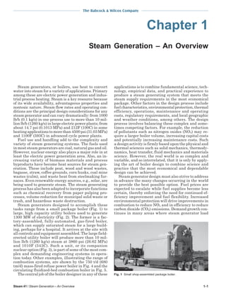
  • 1. The Babcock & Wilcox Company Chapter 1 Steam Generation – An Overview Steam generators, or boilers, use heat to convert water into steam for a variety of applications. Primary among these are electric power generation and industrial process heating. Steam is a key resource because of its wide availability, advantageous properties and nontoxic nature. Steam flow rates and operating conditions are the principal design considerations for any steam generator and can vary dramatically: from 1000 lb/h (0.1 kg/s) in one process use to more than 10 million lb/h (1260 kg/s) in large electric power plants; from about 14.7 psi (0.1013 MPa) and 212F (100C) in some heating applications to more than 4500 psi (31.03 MPa) and 1100F (593C) in advanced cycle power plants. Fuel use and handling add to the complexity and variety of steam generating systems. The fuels used in most steam generators are coal, natural gas and oil. However, nuclear energy also plays a major role in at least the electric power generation area. Also, an increasing variety of biomass materials and process byproducts have become heat sources for steam generation. These include peat, wood and wood wastes, bagasse, straw, coffee grounds, corn husks, coal mine wastes (culm), and waste heat from steelmaking furnaces. Even renewable energy sources, e.g., solar, are being used to generate steam. The steam generating process has also been adapted to incorporate functions such as chemical recovery from paper pulping processes, volume reduction for municipal solid waste or trash, and hazardous waste destruction. Steam generators designed to accomplish these tasks range from a small package boiler (Fig. 1) to large, high capacity utility boilers used to generate 1300 MW of electricity (Fig. 2). The former is a factory-assembled, fully-automated, gas-fired boiler, which can supply saturated steam for a large building, perhaps for a hospital. It arrives at the site with all controls and equipment assembled. The large fielderected utility boiler will produce more than 10 million lb/h (1260 kg/s) steam at 3860 psi (26.62 MPa) and 1010F (543C). Such a unit, or its companion nuclear option (Fig. 3), is part of some of the most complex and demanding engineering systems in operation today. Other examples, illustrating the range of combustion systems, are shown by the 750 t/d (680 tm/d) mass-fired refuse power boiler in Fig. 4 and the circulating fluidized-bed combustion boiler in Fig. 5. The central job of the boiler designer in any of these Steam 41 / Steam Generation – An Overview applications is to combine fundamental science, technology, empirical data, and practical experience to produce a steam generating system that meets the steam supply requirements in the most economical package. Other factors in the design process include fuel characteristics, environmental protection, thermal efficiency, operations, maintenance and operating costs, regulatory requirements, and local geographic and weather conditions, among others. The design process involves balancing these complex and sometimes competing factors. For example, the reduction of pollutants such as nitrogen oxides (NOx) may require a larger boiler volume, increasing capital costs and potentially increasing maintenance costs. Such a design activity is firmly based upon the physical and thermal sciences such as solid mechanics, thermodynamics, heat transfer, fluid mechanics and materials science. However, the real world is so complex and variable, and so interrelated, that it is only by applying the art of boiler design to combine science and practice that the most economical and dependable design can be achieved. Steam generator design must also strive to address in advance the many changes occurring in the world to provide the best possible option. Fuel prices are expected to escalate while fuel supplies become less certain, thereby enforcing the need for continued efficiency improvement and fuel flexibility. Increased environmental protection will drive improvements in combustion to reduce NOx and in efficiency to reduce carbon dioxide (CO2) emissions. Demand growth continues in many areas where steam generator load Fig. 1 Small shop-assembled package boiler. 1-1
  • 2. The Babcock & Wilcox Company power plant thermal efficiency. Also, modularization and further standardization will help reduce fabrication and erection schedules to meet more dynamic capacity addition needs. Steam generation fundamentals Boiling The process of boiling water to make steam is a familiar phenomenon. Thermodynamically, instead of increasing the water temperature, the energy used results in a change of phase from a liquid to a gaseous state, i.e., water to steam. A steam generating system should provide a continuous process for this conversion. The simplest case for such a device is a kettle boiler where a fixed quantity of water is heated (Fig. 6). The applied heat raises the water temperature. Eventually, for the given pressure, the boiling (saturation) temperature is reached and bubbles begin to form. As heat continues to be applied, the temperature remains constant, and steam escapes from the water surface. If the steam is continuously removed from the vessel, the temperature will remain constant until all of the water is evaporated. At this point, heat addition would increase the temperature of the kettle and of any steam remaining in the vessel. To provide a continuous process, all that is needed is a regulated supply of water to the vessel to equal the steam being generated and removed. Technical and economic factors indicate that the most effective way to produce high pressure steam is to heat relatively small diameter tubes containing a continuous flow of water. Regardless of whether the energy source is nuclear or fossil fuel, two distinct boiling systems are Fig. 2 1300 MW coal-fired utility steam generator. may have to cycle up and down more frequently and at a faster rate. There are technologies such as pressurized fluidized-bed combustion and integrated gasification combined cycle systems, plus others, which actually integrate the environmental control with the entire steam generation process to reduce emissions and increase Fig. 3 900 MW nuclear power system. 1-2 Fig. 4 Babcock & Wilcox 750 ton per day mass-fired refuse power boiler. Steam 41 / Steam Generation – An Overview
  • 3. The Babcock & Wilcox Company used to accomplish this task: those that include a steam drum (see Fig. 7a), or fixed steam-water separation point, and those that do not (see Fig. 7b), termed once-through steam generators (OTSG). The most common and simplest to control is the steam drum system. In this system, the drum serves as the point of separation of steam from water throughout its boiler’s load range. Subcooled water (less than boiling temperature) enters the tube to which heat is applied. As the water flows through the tube, it is heated to the boiling point, bubbles are formed, and wet steam is generated. In most boilers, a steam-water mixture leaves the tube and enters the steam drum, where steam is separated from water. The remaining water is then mixed with the replacement water and returned to the heated tube. Without a steam drum, i.e., for an OTSG system, subcooled water also enters the tube to which heat is applied, but the flowing water turns into steam somewhere along the flow path (length of tube), dependent upon water flow rate (boiler load) and heat input rates. Shown in Fig. 7b, the flow rate and heat input are closely controlled and coordinated so that all of the water is evaporated and only steam leaves the tube. There is no need for the steam drum (fixed steamwater separation point). Circulation For both types of boiling systems described above, water must continuously pass through, or circulate through, the tubes for the system to generate steam continuously. For an OTSG, water makes one pass through the boiler’s tubes before becoming steam to be sent to the turbine-generator. However, for those boilers with a fixed steam-water separation point or steam drum, a molecule of water can make many passes through a circulation loop before it leaves as In-Furnace U-Beams Fig. 6 Simple kettle boiler. steam to the turbine-generator. Options for this latter system are shown in Fig. 8. Two different approaches to circulation are commonly used: natural or thermal circulation, and forced or pumped circulation. Natural circulation is illustrated in Fig. 8a. In the downcomer, unheated tube segment A-B, no steam is present. Heat addition generates a steam-water mixture in segment B-C. Because the steam and steam-water mixture in segment B-C are less dense than the water segment A-B, gravity will cause the water to flow downward in segment A-B and will External U-Beams Superheater Steam Drum Feedwater to Drum Downcomer Internal Evaporative Circuit Multi-Cyclone Dust Collector Wing Wall Fuel Bunker Economizer Ash Recycle System Air Heater Gravimetric Feeder Fuel Chute Flue Gas Refractory Line Fluid Bed Cooler Secondary Primary Air Duct to Steam Coil Air Duct Air Duct Fluid Bed Cooler Air Heater Fig. 5 Coal-fired circulating fluidized-bed combustion steam generator. Steam 41 / Steam Generation – An Overview Fig. 7 Boiling process in tubular geometries. 1-3
  • 4. The Babcock & Wilcox Company Fig. 8 Simple circulation systems. cause the steam-water mixture (B-C) to move upward into the steam drum. The rate of water flow or circulation depends upon the difference in average density between the unheated water and the heated steam-water mixture. The total circulation rate in a natural circulation system depends primarily upon four factors: 1) the height of the boiler, 2) the operating pressure, 3) the heat input rate, and 4) the free flow areas of the components. Taller boilers result in a larger total pressure difference between the heated and unheated legs and therefore can produce larger total flow rates. Higher operating pressures provide higher density steam and higher density steam-water mixtures. This reduces the total weight difference between the heated and unheated segments and tends to reduce flow rate. Higher heat input typically increases the amount of steam in the heated segments and reduces the average density of the steam-water mixture, increasing total flow rate. An increase in the cross-sectional (free flow) areas for the water or steamwater mixtures may increase the circulation rate. For each unit of steam produced, the amount of water entering the tube can vary from 3 to 25 units. Forced or pumped circulation is illustrated in Fig. 8b. A mechanical pump is added to the simple flow loop and the pressure difference created by the pump controls the water flow rate. The steam-water separation in the drum requires careful consideration. In small, low pressure boilers, steam-water separation can be easily accomplished with a large drum approximately half full of water. Natural gravity steam-water separation (similar to a kettle) can be sufficient. However, in today’s high ca1-4 pacity, high pressure units, mechanical steam-water separators are needed to economically provide moisture-free steam from the drum. With such devices installed in the drum, the vessel diameter and cost can be significantly reduced. At very high pressures, a point is reached where water no longer exhibits boiling behavior. Above this critical pressure [3200.11 psi (22.1 MPa)], the water temperature continuously increases with heat addition. Steam generators can be designed to operate at pressures above this critical pressure. Drums and steam-water separation are no longer required and the steam generator operates effectively on the oncethrough principle. There are a large number of design methods used to evaluate the expected flow rate for a specific steam generator design and set of operating conditions. In addition, there are several criteria which establish the minimum required flow rate and maximum allowable steam content or quality in individual tubes, as well as the maximum allowable flow rates for the steam drum. System arrangement and key components Most applications of steam generators involve the production of electricity or the supply of process steam. In some cases, a combination of the two applications, called cogeneration, is used. In each application, the steam generator is a major part of a larger system that has many subsystems and components. Fig. 9 shows a modern coal-fired power generating facility; Fig. 10 identifies the major subsystems. Key subsystems include fuel receiving and preparation, steam generator Steam 41 / Steam Generation – An Overview
  • 5. The Babcock & Wilcox Company and combustion, environmental protection, turbinegenerator, and heat rejection including cooling tower. First, follow the fuel and products of combustion (flue gas) through the system. The fuel handling system stores the fuel supply (coal in this example), prepares the fuel for combustion and transports it to the steam generator. The associated air system supplies air to the burners through a forced draft fan. The steam generator subsystem, which includes the air heater, burns the fuel-air mixture, recovers the heat, and generates the controlled high pressure and high temperature steam. The flue gas leaves the steam generator subsystem and selective catalytic reduction (SCR) system if supplied, then passes through particulate collection and sulfur dioxide (SO2) scrubbing systems where pollutants are collected and the ash and solid scrubber residue are removed. The remaining flue gas is then sent to the stack through an induced draft fan. Next, follow the steam-water path. The steam generator (boiler) evaporates water and supplies high temperature, high pressure steam, under carefully controlled conditions, to a turbine-generator set that produces the electricity. The steam may also be reheated in the steam generator, after passing through part of a multi-stage turbine system, by running the exhaust steam back to the boiler convection pass (reheater not shown). Ultimately, the steam is passed from the turbine to the condenser where the remaining waste heat is rejected. Before the water from the condenser is returned to the boiler, it passes through several pumps and heat exchangers (feedwater heaters) to increase its pressure and temperature. The heat absorbed by the condenser is eventually rejected to the atmosphere by one or more cooling towers. These cool- Electricity Fig. 9 Coal-fired utility power plant. ing towers are perhaps the most visible component in the power system (Fig. 9). The natural draft cooling tower shown is basically a hollow cylindrical structure which circulates air and moisture to absorb the heat rejected by the condenser. Such cooling towers exist at most modern power plant sites, both nuclear- and fossil fuel-fired. For an industrial power system, many of the same features are needed. However, the turbine-generator and heat rejection portions are replaced by the process application, such as radiant space heaters or heat exchangers. In a nuclear power system (Fig. 11), the fossil fuelfired steam generator is replaced by a nuclear reactor vessel and, typically, two or more steam generators. The coal handling system is replaced by a nuclear reactor fuel bundle handling and storage facility, and the large scale air pollution control equipment is not needed. Steam Stack Boiler Water from Heaters SCR Substation Transformer Particulate Collector Air Cooling Tower Makeup Pumps Air Heater Combustion Air TurbineGenerator Fuel Condenser Primary Air Fan Induced Draft Fan Forced Draft Fan Water to Boiler Pumps Condensate Pump Low Pressure Heaters SO2 Scrubber Feed Pump High Pressure Heaters (Not Shown: Reheater, Ash and Reagent Handling and Sludge Disposal) Coal Pulverization Coal Supply Fig. 10 Coal-fired utility power plant schematic. Steam 41 / Steam Generation – An Overview 1-5
  • 6. The Babcock & Wilcox Company Fig. 11 Nuclear power plant schematic. Fossil steam generator classifications Modern steam generating systems can be classified by various criteria. These include end use, firing method, operating pressure, fuel, and circulation method. Utility steam generators are used primarily to generate electricity in large central power stations. They are designed to optimize overall thermodynamic efficiency at the highest possible availability. New units are typically characterized by large, main steam flow rates with superheated steam outlet pressures from 1800 to 3860 psi (12.41 to 26.62 MPa) with steam temperatures at or above 1050F (566C). A key characteristic of newer units is the use of a reheater section to increase overall cycle efficiency. Industrial steam generators generally supply steam to processes or manufacturing activities and are designed with particular attention to: 1) process controlled (usually lower) pressures, 2) high reliability with minimum maintenance, 3) use of one or more locally inexpensive fuels, especially process byproducts or wastes, and 4) low initial capital and minimum operating costs. On a capacity basis, the larger users of such industrial units are the pulp and paper industry, municipal solid waste reduction industry, food processing industry, petroleum/petrochemical industry, independent power producers and cogenerators, and some large manufacturing operations. Operating pressures range from 150 to 1800 psi (1.04 to 12.41 MPa) with saturated or superheated steam conditions. Impact of energy source The primary fuel selected has perhaps the most significant impact on the steam generator system configuration and design. In the case of nuclear energy, a truly unique system for containing the fuel and the nuclear reaction products has been developed with an 1-6 intense focus on safety and protecting the public from radiation exposure. Acceptable materials performance in the radiative environment and the long term thermal-hydraulic and mechanical performance are central to system design. When fossil, biomass, or byproduct fuels are burned, widely differing provisions must be made for fuel handling and preparation, fuel combustion, heat recovery, fouling of heat transfer surfaces, corrosion of materials, and emissions control. For example, in a natural gas-fired unit (Fig.12), there is minimal need for fuel storage and handling. Only a small furnace is needed for combustion, and closely spaced heat transfer surfaces may be used because of lack of ash deposits (fouling). The corrosion allowance is relatively small and the emissions control function is primarily for NOx formed during the combustion process. The result is a relatively small, compact and economical design. If a solid fuel such as coal (which has a significant level of noncombustible ash) is used, the overall system is much more complex. This system could include extensive fuel handling and preparation facilities, a much larger furnace, and more widely spaced heat transfer surfaces. Additional components could be special cleaning equipment to reduce the impact of fouling and erosion, air preheating to dry the fuel and enhance combustion, more extensive environmental equipment, and equipment to collect and remove solid wastes. The impact of fuel alone on a utility boiler design is clearly indicated in Fig. 12, where both steam generators produce the same steam flow rate. Further adding to the size and cost difference, but not shown, are the facts that the coal-fired boiler will be wider (dimension not shown) and will require more flue gas cleanup equipment to meet emissions requirements. The particular challenge when burning different solid fuels is indicated in Fig. 13, where provision is made for burning both pulverized (finely ground) coal using the burners and for wood chips and bark which are burned on the moving grate (stoker) at the bottom of the unit. Impact of steam conditions The steam temperature and pressure for different boiler applications can have a significant impact on design. Fig. 14 identifies several typical boiler types, as well as the relative amount of heat input needed, for water heating, evaporation (boiling), superheating, and reheating, if required. The relative amount of energy needed for evaporation is dramatically reduced as operating pressure is increased. As a result, the relative amount of physical heat transfer surface (tubes) dedicated to each function can be dramatically different. Fossil fuel systems Fossil fuel steam generator components Modern steam generators are a complex configuration of thermal-hydraulic (steam and water) sections which preheat and evaporate water, and superheat steam. These surfaces are arranged so that: 1) the fuel can be burned completely and efficiently while minimizing emissions, 2) the steam is generated at the required flow rate, pressure and temperature, and 3) Steam 41 / Steam Generation – An Overview
  • 7. The Babcock & Wilcox Company Fig. 12 Comparison of gas- and coal-fired steam generators. the maximum amount of energy is recovered. A relatively simple coal-fired utility boiler is illustrated in Fig. 15. The major components in the steam generating and heat recovery system include: 1. 2. 3. 4. 5. 6. 7. 8. furnace and convection pass, steam superheaters (primary and secondary), steam reheater, boiler or steam generating bank (industrial units only), economizer, steam drum, attemperator and steam temperature control system, and air heater. These components are supported by a number of subsystems and pieces of equipment such as coal pulverizers, combustion system, flues, ducts, fans, gas-side cleaning equipment and ash removal equipment. The furnace is a large enclosed open space for fuel combustion and for cooling of the flue gas before it enters the convection pass. Excessive gas temperatures leaving the furnace and entering the tube bundles could cause particle accumulation on the tubes or excessive tube metal temperatures. The specific geometry and dimensions of the furnace are highly influenced by the fuel and type of combustion equipment. In this case, finely ground or pulverized coal is blown into the furnace where it burns in suspension. The products of combustion then rise through the upper furnace. The superheater, reheater and economizer surfaces are typically located in the flue gas horizontal and vertical downflow sections of the boiler enclosure, called the convection pass. In modern steam generators, the furnace and convection pass walls are composed of steam- or watercooled carbon steel or low alloy tubes to maintain wall Steam 41 / Steam Generation – An Overview metal temperatures within acceptable limits. These tubes are connected at the top and bottom by headers, or manifolds. These headers distribute or collect the water, steam or steam-water mixture. The furnace wall tubes in most modern units also serve as key steam generating components or surfaces. The tubes are welded together with steel bars to provide membrane wall panels which are gas-tight, continuous and rigid. The tubes are usually prefabricated into shippable membrane panels with openings for burners, observation doors, sootblowers (boiler gas-side surface cleaning equipment) and gas injection ports. Superheaters and reheaters are specially designed in-line tube bundles that increase the temperature of saturated steam. In general terms, they are simple single-phase heat exchangers with steam flowing inside the tubes and the flue gas passing outside, generally in crossflow. These critical components are manufactured from steel alloy material because of their high operating temperature. They are typically configured to help control steam outlet temperatures, keep metal temperatures within acceptable limits, and control steam flow pressure loss. The main difference between superheaters and reheaters is the steam pressure. In a typical drum boiler, the superheater outlet pressure might be 2700 psi (18.62 MPa) while the reheater outlet might be only 580 psi (4.0 MPa). The physical design and location of the surfaces depend upon the desired outlet temperatures, heat absorption, fuel ash characteristics and cleaning equipment. These surfaces can be either horizontal or vertical as shown. The superheater and sometimes reheater are often divided into multiple sections to help control steam temperature and optimize heat recovery. The heat transfer surface in the furnace may not be sufficient to generate enough saturated steam for 1-7
  • 8. The Babcock & Wilcox Company Fig. 13 Large industrial boiler with multiple fuel capability. the particular end use. If this is the case, an additional bank of heat exchanger tubes called the boiler bank or steam generating bank is added. (See Fig. 13.) This is needed on many smaller, low pressure industrial boilers, but is not often needed in high pressure utility boilers. This boiler bank is typically composed of the steam drum on top, a second drum on the bottom, and a series of bent connecting tubes. The steam drum internals and tube sizes are arranged so that subcooled water travels down the tubes (farthest from the furnace) into the lower drum. The water is then distributed to the other tubes where it is partially converted to steam and returned to the steam drum. The lower drum is often called the mud drum because this is where sediments found in the boiler water tend to settle out and collect. The economizer is a counterflow heat exchanger for recovering energy from the flue gas beyond the superheater and, if used, the reheater. It increases the temperature of the water entering the steam drum. The tube bundle is typically an arrangement of parallel horizontal serpentine tubes with the water flowing inside but in the opposite direction (counterflow) to the flue gas. Tube spacing is as tight as possible to promote heat transfer while still permitting adequate tube surface cleaning and limiting flue gas-side pressure loss. By design, steam is usually not generated inside these tubes. The steam drum is a large cylindrical vessel at the top of the boiler, in which saturated steam is separated from the steam-water mixture leaving the boiler tubes. Drums can be quite large with diameters of 3 to 6 ft 1-8 (0.9 to 1.8 m) and lengths approaching 100 ft (30.5 m). They are fabricated from thick steel plates rolled into cylinders with hemispherical heads. They house the steam-water separation equipment, purify the steam, mix the replacement or feedwater and chemicals, and provide limited water storage to accommodate small changes in unit load. Major connections to the steam drum are provided to receive the steam-water mixture from the boiler tubes, remove saturated steam, add replacement or makeup water, and return the near saturated water back to the inlet of the boiler tubes. The steam temperature control system can be complex and include combinations of recirculating some of the flue gas to the bottom or top of the furnace, providing special gas flow passages at the back end of the steam generator, adjusting the combustion system, and adding water or low temperature steam to the high temperature steam flow (attemperation). The component most frequently used for the latter is called a spray attemperator. In large utility units, attemperators with direct injection of water or low temperature steam are used for dynamic control because of their rapid response. They are specially designed to resist thermal shock and are frequently located at the inlet of the superheater or between superheater sections to better control the superheater outlet metal temperatures. Positioning of individual superheater sections can also help maintain proper outlet steam temperatures. The air heater is not a portion of the steam-water circuitry, but serves a key role in the steam generator system heat transfer and efficiency. In many cases, especially in high pressure boilers, the temperature of the flue gas leaving the economizer is still quite high. The air heater recovers much of this energy and adds it to the combustion air to reduce fuel use. Designs include tubular, flat plate, and regenerative heat exchangers, among others. Steam-water flow system The steam-water components are arranged for the most economical system to provide a continuous supply of steam. The circulation system (excluding reheater) for a natural circulation, subcritical pressure, drum type steam generator is shown in Fig. 16. Feed- Fig. 14 Steam generator energy absorption by function. Steam 41 / Steam Generation – An Overview
  • 9. The Babcock & Wilcox Company water enters the bottom header (A) of the economizer and passes upward in the opposite direction to the flue gas. It is collected in an outlet header (B), which may also be located in the flue gas stream. The water then flows through a number of pipes which connect the economizer outlet header to the steam drum. It is sometimes appropriate to run these tubes vertically (BC) through the convection pass to economizer outlet headers located at the top of the boiler. These tubes can then serve as water-cooled supports for the horizontal superheater and reheater when these banks span too great a distance for end support. The feedwater is injected into the steam drum (D) where it mixes with the water discharged from the steam-water separators before entering connections to the downcomer pipes (D-E) which exit the steam drum. The water travels around the furnace water wall circuits to generate steam. The water flows through the downcomer pipes (D-E) to the bottom of the furnace where supply tubes (E-F) route the circulating water to the individual lower furnace panel wall headers (F). The water rises through the furnace walls to individual outlet headers (G), absorbing energy to become a steam-water mixture. The mixture leaves the furnace wall outlet headers by means of riser tubes (G-D), to be discharged into the drum and steam-water separators. The separation equipment returns essentially steam-free water to the downcomer inlet connections. The residual moisture in the steam that leaves the primary steam separation devices is removed in secondary steam separators, and dry steam is discharged to the superheater through a number of drum outlet connections (H-I and H-J). The steam circuitry serves dual functions: cooling the convection pass enclosure, and generating the required superheated steam conditions. Steam from the drum passes through multiple connections to a Fig. 15 Coal-fired utility boiler. Steam 41 / Steam Generation – An Overview Fig. 16 Coal-fired boiler steam-water circulation system. header (I) supplying the roof tubes and, separately, to headers (J) supplying the membrane panels in the pendant convection pass (so named because the superheater/reheater vertical tubes are hanging from supports above). The steam flows through these membrane panels to outlet headers (K). Steam from these headers and the roof tube outlet headers (L) then provides the cooling for the horizontal convection pass enclosure (L-M) (so named because the superheater/ reheater/economizer tubes are horizontal in this flue gas downpass). Steam flows downward through these panels and is collected in outlet headers (M) just upstream of the economizer bank. Steam flow then rises through the primary superheater and discharges through the outlet header (N) and connecting piping equipped with a spray attemperator (O). It then enters the secondary superheater inlet header (P), flowing through the superheater sections to an outlet header (Q). A discharge pipe (R) terminates outside of the boiler enclosure where the main steam lines route the steam flow to the control valves and turbine. Combustion system and auxiliaries Most of the non-steam generating components and auxiliaries used in coal-fired steam generators are part of the fuel preparation and combustion systems. These include: 1. fuel preparation: feeders and coal pulverizers, 2. combustion system: burners, flame scanners, lighters, controls, windbox, 3. air-gas handling: fans, flues and ducts, dampers, control and measurement systems, silencers, and 4. other components and auxiliaries: sootblowers (heat transfer surface cleaning equipment), ash collection and handling equipment, control and monitoring equipment. 1-9
  • 10. The Babcock & Wilcox Company Because of their intimate relationship with the steam generation process, many of these components are supplied with the boiler. If not, careful specification and interaction with the steam generator manufacturer are critical. The combustion system has a dramatic impact on overall furnace design. Wall mounted burners are shown in Figs. 15 and 17. These are typical for large coal-, oil-, or gas-fired units today. However, a variety of other systems are also used and are continuing to be developed to handle the variety of fuel characteristics and unit sizes. Other combustion systems include stokers (Figs. 4 and 13), Cyclone furnaces, and fluidized-bed combustion units (Fig. 5). All have their strengths and weaknesses for particular applications. Key elements of these systems involve the need to control the formation and emission of pollutants, provide complete efficient combustion, and handle inert material found in the fuel. The fuel characteristics play a central role in how these functions are met and how the equipment is sized and designed. Air-gas flow system Many of these auxiliaries are identified in Fig. 17 along with the air-gas flow path in the large coal-fired utility boiler. Air is supplied by the forced draft fan (A) to the air heater (B) where it is heated to recover energy and enhance combustion. Most of the hot air (typically 70 to 80%), called secondary air, passes directly to the windboxes (C) where it is distributed to individual burners. The remaining 20 to 30%, called primary air, passes to the booster (or primary air) fan and then to the coal pulverizers (D) where the coal is dried and ground. The hot primary air then pneumatically conveys the pulverized coal to the burners (E) where it is mixed with the secondary air for combustion. The coal and air are rapidly mixed and burned in the furnace (F) and the flue gas then passes up through the furnace, being cooled primarily by radiation until it reaches the furnace exit (G). The gas then progressively passes through the secondary superheater, reheater, primary superheater and economizer before leaving the steam generator enclosure (H). The gas passes through the air heater (B) and then through any pollution control equipment and induced draft fan (I) before being exhausted to the atmosphere. Emissions control A key element of fossil fuel-fired steam generator system design is environmental protection. A broad range of government regulations sets limits on primary gaseous, liquid and solid waste emissions from the steam generating process. For coal-, oil-, and gas-fired units, the primary air pollutant emissions include sulfur dioxide (SO2), nitrogen oxides (NOx) and airborne particulate or flyash. Water discharges include trace chemicals used to control corrosion and fouling as well as waste heat rejected from the condenser. Solid waste primarily involves the residual ash from the fuel and any spent sorbent from the pollution control systems. The gaseous and solid waste from the fuel and combustion process can be minimized by fuel selection, 1-10 Fig. 17 Coal-fired boiler air/gas flow path. control of the combustion process, and equipment located downstream of the steam generator. SO2 emissions may be reduced by using fuels which contain low levels of sulfur, by fluidized-bed combustors, or by using a post-combustion scrubber system. Combustion NOx emissions are typically controlled by using equipment such as special low NOx burners or fluidized-bed combustors. Where it is required to significantly reduce NOx emissions (to levels lower than is practically achieved by combustion techniques alone), back-end or post-combustion techniques, such as selective catalytic reduction (SCR) or selective noncatalytic reduction (SNCR) technologies, are employed. Flyash or airborne particulate is collected by either a fabric filter (baghouse) or electrostatic precipitator (ESP) with removal efficiencies above 99%. The particulate collection equipment and SO 2 scrubbers produce solid byproduct streams which must be safely landfilled or used for some industrial applications. The water discharges are minimized by installing recirculating cooling systems. An example of this is cooling towers that reject the waste heat from the power cycle to the air, instead of to a water source. These are used on virtually all new fossil and nuclear power plants. Chemical discharges are minimized by specially designed zero discharge systems. A set of emissions rates before and after control for a typical 500 MW power plant is shown in Table 1. Nuclear steam generating systems Overview Nuclear steam generating systems include a series of highly specialized heat exchangers, pressure vessels, pumps and components which use the heat generated by nuclear fission reactions to efficiently and Steam 41 / Steam Generation – An Overview
  • 11. The Babcock & Wilcox Company Table 1 Typical 500 MW Subcritical Coal-Fired Steam Generator Emissions and Byproducts* Power System Characteristics • 500 MW net • 196 t/h (49.4 kg/s) bituminous coal − 2.5% sulfur − 16% ash − 12,360 Btu/lb (28,749 kJ/kg) • 65% capacity factor Emission SOx as SO2 NOx as NO2 CO2 Flyash to air** Thermal discharge to water sources Ash to landfill** Scrubber sludge: gypsum plus water Typical Control Equipment Discharge Rate  t/h (tm /h) Uncontrolled Controlled Wet limestone scrubber 9.3 (8.4) Low NOx burners and SCR 2.9 (2.6) Not applicable 485 (440) Electrostatic precipitator or baghouse 22.9 (20.8) Natural draft cooling tower 2.8 x 10⁹ Btu/h (821 MWt ) Controlled landfill 9.1 (8.3) Controlled landfill or wallboard quality gypsum 0 (0) 0.3 0.1  0.05 ∼0 32 27.7 (0.3) (0.1)  (0.04) (0) (29) (25) * See Chapter 32, Table 1, for a modern 615 MW supercritical coal-fired steam generator. ** As flyash emissions to the air decline, ash to landfill increases. safely generate steam. The system is based upon the energy released when atoms within certain materials, such as uranium, break apart or fission. Fission occurs when a fissionable atom nucleus captures a free subatomic particle – a neutron. This upsets the internal forces which hold the atom nucleus together. The nucleus splits apart producing new atoms as well as an average of two to three neutrons, gamma radiation and energy. The nuclear steam supply system (NSSS) is designed to serve a number of functions: 1) house the nuclear fuel, 2) stimulate the controlled fission of the fuel, 3) control the nuclear reaction rate to produce the required amount of thermal energy, 4) collect the heat and generate steam, 5) safely contain the reaction products, and 6) provide backup systems to prevent release of radioactive material to the environment. Various systems have been developed to accomplish these functions. The main power producing system in commercial operation today is the pressurized water reactor (PWR). A key difference between the nuclear and chemical energy driven systems is the quantity of fuel. The energy released per unit mass of nuclear fuel is many orders of magnitude greater than that for chemical based fuels. For example, 1 lb (0.454 kg) of 3% enriched uranium fuel produces about the same amount of thermal energy in a commercial nuclear system as 100,000 lb (45,360 kg) of coal in a fossil-fired steam system. While a 500 MW power plant must handle approximately one million tons of coal per year, the nuclear plant will handle only 10 tons of fuel. The fossil fuel plant must be designed for a continuous fuel supply process, while most nuclear plants use a batch fuel process, where about one third of the fuel is replaced during periodic outages. However, once the steam is generated, the balance of the power producing system (turbine, condenser, cooling system, etc.) is similar to that used in the fossil fuel plant. Steam 41 / Steam Generation – An Overview Nuclear steam system components A typical nuclear steam system from The Babcock & Wilcox Company (B&W) is shown in Fig. 3 and a simplified schematic is shown in Fig. 18. This nuclear system consists of two coolant loops. The primary loop cools the reactor, transports heat to two or more steam generators (only one shown), and returns coolant to the reactor by four or more primary coolant pumps (only one shown). The coolant is high purity, subcooled, single-phase water flowing at very high rates [350,000 to 450,000 GPM (22,100 to 28,400 l/s)] at around 2200 psi (15.17 MPa) and an average temperature of approximately 580F (304C). The primary loop also contains a pressurizer to maintain the loop pressure at design operating levels. The secondary loop includes the steam generation and interface with the balance of the power plant. High purity water from the last feedwater heater passes through the steam generator and is converted into steam. From the steam generator outlet, the saturated or superheated steam flows out of the containment building to the high pressure turbine. The operating pressure is typically around 1000 psi (6.9 MPa). The balance of the secondary loop resembles fossil fuel-fired systems. (See Figs. 10 and 11.) The center of the NSSS is the reactor vessel and reactor core (Fig. 19). The fuel consists of compressed pellets [for example, 0.37 in. (9.4 mm) diameter by 0.7 in. (18 mm) long] of 2.5 to 5% enriched uranium oxide. These pellets are placed in zircaloy tubes which are sealed at both ends to protect the fuel and to contain the nuclear reaction products. The tubes are assembled into bundles with spacer and closure devices. These bundles are then assembled into the nuclear fuel core. The reactor enclosure (Fig. 19) is a low alloy steel pressure vessel lined with stainless steel for corrosion protection. The rest of the reactor includes flow distribution devices, control rods, core support structures, 1-11
  • 12. The Babcock & Wilcox Company steam generator upper shell is mixed with feedwater and is returned to the bottom of the tube bundle. The pressurizer is a simple cylindrical pressure vessel which contains both water and steam at equilibrium. Electrical heaters and spray systems maintain the pressure in the pressurizer vessel and the primary loop within set limits. The primary loop circulating pumps maintain high flow rates to the reactor core to control its temperature and transfer heat to the steam generators. A number of support systems are also provided. These include reactor coolant charging systems, makeup water addition, spent fuel storage cooling, and decay heat removal systems for when the reactor is shut down. Other specialized systems protect the reactor system in the case of a loss of coolant event. The key function of these systems is to keep the fuel bundle temperature within safe limits if the primary coolant flow is interrupted. Fig. 18 Nuclear steam system schematic. thermal shielding and moderator. The moderator in this case is water which serves a dual purpose. It reduces the velocity of the neutrons thereby making the nuclear reactions more likely. It also serves as the coolant to maintain the core materials within acceptable temperature limits and transports thermal energy to the steam generators. The control rods contain neutron absorbing material and are moved into and out of the nuclear core to control the energy output. The steam generators can be of two types, oncethrough (Fig. 20) and recirculating (Fig. 21). In both types, the pressure vessel is a large heat exchanger designed to generate steam for the secondary loop from heat contained in the primary coolant. The primary coolant enters a plenum and passes through several thousand small diameter [approximately 0.625 in. (15.9 mm)] Inconel® tubes. The steam generator is a large, carbon steel pressure vessel. Specially designed tubesheets, support plates, shrouds, and baffles provide effective heat transfer, avoid thermal expansion problems, and avoid flow-induced vibration. In the once-through steam generator (OTSG), Fig. 20, the secondary loop water flows from the bottom to the top of the shell side of the tube bundle and is continuously converted from water to superheated steam. The superheated steam then passes to the high pressure turbine. In the recirculating steam generator (RSG), Fig. 21, water moves from the bottom to the top of the shell side of the tube bundle being converted partially into steam. The steam-water mixture passes into the upper shell where steam-water separators supply saturated dry steam to the steam generator outlet. The steam is sent to the high pressure turbine. The water leaving the 1-12 Nuclear steam system classifications A variety of reactor systems have been developed to recover thermal energy from nuclear fuel and to generate steam for power generation. These are usually identified by their coolant and moderator types. The principal systems for power generation include: 1. Pressurized water reactor (PWR) This is the system discussed above, using water as both reactor coolant and moderator, and enriched uranium oxide as the fuel. 2. Boiling water reactor (BWR) The steam generator is eliminated and steam is generated directly in the reactor core. A steam-water mixture cools and moderates the reactor core. Enriched uranium oxide fuel is used. Fig. 19 Reactor vessel and internals. Steam 41 / Steam Generation – An Overview
  • 13. The Babcock & Wilcox Company 3. CANDU (PHWR) Heavy water (deuterium) is used as the moderator and primary loop coolant. The reactor configuration is unique but the steam generator is similar to the recirculating steam generator for the PWR. Natural (not enriched) uranium oxide is used as the fuel. 4. Gas-cooled reactors These are a variety of gascooled reactors which are typically moderated by graphite and cooled by helium or carbon dioxide. 5. Breeder reactors These are advanced reactor systems using sodium as the reactor coolant with no moderator. These systems are specially designed to produce more fissionable nuclear fuel than they use. Engineered safety systems Safety is a major concern in the design, construction and operation of nuclear power generating facilities. The focus of these efforts is to minimize the likelihood of a release of radioactive materials to the environment. Three approaches are used to accomplish this goal. First, the nuclear power industry has developed one of the most extensive and rigorous quality control programs for the design, construction and maintenance of nuclear facilities. Second, reactor systems are designed with multiple barriers to prevent radioactive material release. These include high temperature ceramic fuel pellets, sealed fuel rods, reactor vessel and primary coolant system, and the contain- Fig. 21 Recirculating steam generator. ment building including both the carbon steel reactor containment vessel and the reinforced concrete shield building. The third approach includes a series of engineered safety systems to address loss of coolant conditions and maintain the integrity of the multiple barriers. These systems include: 1. emergency reactor trip systems including rapid insertion of control rods and the addition of soluble neutron poisons in the primary coolant to shut down the nuclear reaction, 2. high and low pressure emergency core cooling systems to keep the reactor core temperature within acceptable limits and remove heat from the fuel in the event of a major loss of primary coolant or a small pipe break, 3. a heat removal system for the cooling water and containment building, and 4. spray and filtering systems to collect and remove radioactivity from the containment building. Fig. 20 Once-through steam generator. Steam 41 / Steam Generation – An Overview Because of the high power densities and decay heat generation, the reactor integrity depends upon the continuous cooling of the nuclear fuel rods. Multiple independent components and backup power supplies are provided for all critical systems. 1-13
  • 14. The Babcock & Wilcox Company Steam system design Steam generator interfaces The steam generator system’s primary function is to convert chemical or nuclear energy bound in the fuel to heat and produce high temperature, high pressure steam. The variety of fuel sources, the high temperature nature of these processes, and the large number of subsystem interfaces contribute to the challenging nature of the design process. The initial steps in evaluating the steam generating system include establishing key interfaces with other plant systems and with the power cycle. These are typically set by the end user or consulting engineer after an in-depth evaluation indicates: 1) the need for the expanded power supply or steam source, 2) the most economical fuel selection and type of steam producing system, 3) the plant location, and 4) the desired power cycle or process steam conditions. The key requirements fall into six major areas: 1. Steam minimum, nominal, and maximum flow rates; pressure and temperature; need for one or more steam reheat stages; auxiliary equipment steam usage; and future requirements. 2. Source of the steam flow makeup or replacement water supply, water chemistry and inlet temperature. 3. The type and range of fuels considered, including worst case conditions, and the chemical analyses (proximate and ultimate analyses) for each fuel or mixture of fuels. 4. Elevation above sea level, overall climate history and forecast, earthquake potential and space limitations. 5. Emissions control requirements and applicable government regulations and standards. 6. The types of auxiliary equipment; overall plant and boiler efficiency; access needs; evaluation penalties, e.g., power usage; planned operating modes including expected load cycling requirements, e.g., peaking, intermediate or base load; and likely future plant use. When these interfaces are established, boiler design and evaluation may begin. Systematic approach There are a variety of evaluation approaches that can be used to meet the specific steam generator performance requirements. These include the multiple iterations commonly found in thermal design where real world complexities and nonlinear, noncontinuous interactions prevent a straightforward solution. The process begins by understanding the particular application and system to define conditions such as steam flow requirements, fuel source, operating dynamics, and emissions limits, among others. From these, the designer proceeds to assess the steam generator options, interfaces, and equipment needs to achieve performance. Using a coal-fired boiler as an example, a systematic approach would include the following: 1. Specify the steam supply requirements to define the overall inputs of fuel, air and water, and the steam output conditions. 1-14 2. Evaluate the heat balances and heat absorption by type of steam generator surface. 3. Perform combustion calculations to define heat input and gas flow requirements. 4. Configure the combustion system to complete the combustion process while minimizing emissions (fuel preparation, combustion and air handling). 5. Configure the furnace and other heat transfer surfaces to satisfy temperature, material, and performance tradeoffs while meeting the system control needs. 6. Size other water-side and steam-side components. 7. Specify the back-end tradeoffs on the final heat recovery devices such as water heaters (economizers) and air heaters. 8. Check the steam generating system performance to ensure that the design criteria are met. 9. Verify overall unit performance. 10. Repeat steps 2 through 9 until the desired steam mass flow and temperature are achieved over the specified range of load conditions. 11. Use American Society of Mechanical Engineers (ASME) Code rules to design pressure parts to meet the anticipated operating conditions and complete detailed mechanical design. 12. Design and integrate environmental protection equipment to achieve prescribed emissions levels. 13. Incorporate auxiliaries as needed, such as tube surface cleaning equipment, fans, instrumentation and controls, to complete the design and assure safe and continuous operation. The life cycle and daily operation of the steam generator (and the plant in which it will operate) are important elements to be considered from the beginning of the design and throughout the design process. Today, some steam generators will be required to operate efficiently and reliably for up to 60 years or more. During this time, many components will wear out because of the aggressive environment, so routine inspection of pressure parts is needed to assure continued reliability. Unit operating procedures, such as the permitted severity and magnitude of transients, may be monitored to prevent reduced unit life. Operating practices including water treatment, cycling operation procedures, and preventive maintenance programs, among others, can significantly affect steam generator availability and reliability. Key unit components may be upgraded to improve performance. In each case, decisions made during the design phase and subsequent operation can substantially enhance the life and performance of the unit. System design example Now that the basic fossil fuel and nuclear steam generating systems have been described, it is appropriate to explore the general design and engineering process. While each of the many systems requires specialized evaluations, they share many common elements. To illustrate how the design process works, a small industrial B&W PFI gas-fired boiler has been selected for discussion. (See Figs. 22 and 23.) Basically, the customer has one overriding need: when the valve is turned on, steam is expected to be Steam 41 / Steam Generation – An Overview
  • 15. The Babcock & Wilcox Company supplied at the desired pressure, temperature and flow rate. In this example, the customer specifies 400,000 lb/h (50.4 kg/s) of superheated steam at 600 psi (4.14 MPa) and 850F (454C). The customer has agreed to supply high purity feedwater at 280F (138C) and to supply natural gas as a fuel source. As with all steam generating systems, there are a number of additional constraints and requirements as discussed in Steam generator interfaces, but the major job of the steam generator or boiler is to supply steam. Combustion of the natural gas produces a stream of combustion products or flue gas at perhaps 3600F (1982C). To maximize the steam generator thermal efficiency, it is important to cool these gases as much as possible while generating the steam. The minimum flue gas outlet temperature is established based upon technical and economic factors (discussed below). For now, a 310F (154C) outlet temperature to the exhaust stack is selected. The approximate steam and flue gas temperature curves are shown in Fig. 24 and define the heat transfer process. The heat transfer surface for the furnace, boiler bank, superheater and air heater is approximately 69,000 ft2 (6410 m2). From a design perspective, the PFI boiler can be viewed as either a steam heater or gas cooler. The latter approach is most often selected for design. The design fuel heat input is calculated by dividing the steam heat output by the target steam generator thermal efficiency. Based upon the resulting fuel flow, combustion calculations define the air flow requirements and combustion products gas weight. The heat transfer surface is then configured in the most economical way to cool the flue gas to the temperature necessary for the target steam generator efficiency. Before proceeding to follow the gas through the cooling process, the amount of heat recovery for each of the different boiler surfaces (superheater and boiler) must be established. Fig. 25 illustrates the water heating process from an inlet temperature of 280F (138C) to the superheater Fig. 22 Small PFI industrial boiler. Steam 41 / Steam Generation – An Overview Fig. 23 Small industrial boiler – sectional view. steam outlet temperature of 850F (454C). This curve indicates that about 20% of the heat absorbed is used to raise the water from its inlet temperature to the saturation temperature of 490F (254C). 60% of the energy is then used to evaporate the water to produce saturated steam. The remaining 20% of the heat input is used to superheat or raise the steam temperature to the desired outlet temperature of 850F (454C). The fuel and the combustion process selected set the geometry of the furnace. In this case, simple circular burners are used. The objective of the burners is to mix the fuel and air rapidly to produce a stable flame and complete combustion while minimizing the formation of NOx emissions. Burners are available in several standardized sizes. The specific size and number are selected from past experience to provide the desired heat input rate while permitting the necessary level of load range control. The windbox, which distributes the air to individual burners, is designed to provide a uniform air flow at low enough velocities to permit the burners to function properly. The furnace volume is then set to allow complete fuel combustion. The distances between burners and between the burners and the floor, roof, and side walls are determined from the known characteristics of the particular burner flame. Adequate clearances are specified to prevent flame impingement on the furnace surfaces, which could overheat the tubes and cause tube failures. Once the furnace dimensions are set, this volume is enclosed in a water-cooled membrane panel surface. This construction provides a gas-tight, all steel enclosure which minimizes energy loss, generates some steam and minimizes furnace maintenance. As shown in Fig. 23, the roof and floor tubes are inclined slightly to enhance water flow and prevent steam from collecting on the tube surface. Trapped steam could result in overheating of the tubes. Heat transfer from the flame to the furnace enclosure surfaces occurs primarily by thermal radiation. As a result, the heat input rates per 1-15
  • 16. The Babcock & Wilcox Company Fig. 24 Industrial boiler – temperature versus heat transfer surface. unit area of surface are very high and relatively independent of the tubewall temperatures. Boiling water provides an effective means to cool the tubes and keep the tube metal temperatures within acceptable limits as long as the boiling conditions are maintained. Fig. 26 shows the effect of the furnace on gas temperature. The gas temperature is reduced from 3600 at point A to 2400F at point B (1982 to 1316C), while boiling takes place in the water walls (points 1 to 2). A large amount of heat transfer takes place on a small amount of surface. From the furnace, the gases pass through the furnace screen tubes shown in Fig. 23. The temperature drops a small amount [50F (28C)] from points B to C in Fig. 26, but more importantly, the superheater surface is partially shielded from the furnace thermal radiation. The furnace screen tubes are connected to the drum and contain boiling water. Next, the gas passes through the superheater where the gas temperature drops from 2350 at point C to 1750F at point D (1288 to 954C). Saturated steam from the drum is passed through the superheater tubing to raise its temperature from 490F (254C) saturation temperature to the 850F (454C) desired outlet temperature (points 5 to 4). The location of the superheater and its configuration are critical in order to keep the steam outlet temperature constant under all load conditions. This involves radiation heat transfer from the furnace with convection heat transfer from the gas passing across the surface. In addition, where dirty gases such as combustion products from coal are used, the spacing of the superheater tubes is also adjusted to accommodate the accumulation of fouling ash deposits and the use of cleaning equipment. After the superheater, almost half of the energy in the gas stream has been recovered with only a small amount of heat transfer surface [approximately 6400 ft2 (595 m2)]. This is possible because of the large temperature difference between the gas and the boiling 1-16 water or steam. The gas temperature has now been dramatically reduced, requiring much larger heat transfer surfaces to recover incremental amounts of energy. The balance of the steam is generated by passing the gas through the boiler bank. (See Figs. 22 and 23.) This bank is composed of a large number of watercontaining tubes that connect the steam drum to a lower (mud) drum. The temperature of the boiling water is effectively constant (points 5 to 6 in Fig. 26), while the gas temperature drops by almost 1000F (556C) to an outlet temperature of 760F (404C), between points D and E. The tubes are spaced as closely as possible to increase the gas flow heat transfer rate. If a particulate-laden gas stream were present, the spacing would be set to limit erosion of the tubes, reduce the heat transfer degradation due to ash deposits, and permit removal of the ash. Spacing is also controlled by the allowable pressure drop across the bank. In addition, a baffle can be used in the boiler bank bundle to force the gas to travel at higher velocity through the bundle, increase the heat transfer rate, and thereby reduce the bundle size and cost. To recover this additional percentage of the supplied energy, the boiler bank contains more than 32,000 ft2 (3000 m2) of surface, or approximately nine times more surface per unit of energy than in the high temperature furnace and superheater. At this point in the process, the temperature difference between the saturated water and gas is only 270F (150C), between points 6 and E in Fig. 26. Economics and technical limits dictate the type and arrangement of additional heat transfer surfaces. An economizer or water-cooled heat exchanger could be used to heat the makeup or feedwater and cool the gas. The lowest gas exit temperature possible is the inlet temperature of the feedwater [280F (138C)]. However, the economizer would have to be infinitely large to accomplish this goal. Even if the exit gas temperature is 310F (154C), the temperature difference at this point in the heat exchanger would only be 30F (17C), still making the heat exchanger relatively large. Instead of incorporating an economizer, an air preheater could be used to recover the remaining gas energy and preheat the combustion air. This would reduce the Fig. 25 Steam-water temperature profile. Steam 41 / Steam Generation – An Overview
  • 17. The Babcock & Wilcox Company natural gas needed to heat the steam generator. Air heaters can be very compact. Also, air preheating can enhance the combustion of many difficult to burn fuels such as coal. All of the parameters are reviewed to select the most economical solution that meets the technical requirements. In this case, the decision has been made to use an air heater and not an economizer. The air heater is designed to take 80F (27C) ambient air (point 9) and increase the temperature to 570F (299C), at point 8. This hot air is then fed to the burners. At the same time, the gas temperature is dropped from 760F (404C) to the desired 310F (154C) outlet temperature (points E to F). If a much lower gas outlet temperature than 310F (154C) is used, the heat exchanger surfaces may become uneconomically large, although this is a case by case decision. In addition, for fuels such as oil or coal which can produce acid constituents in the gas stream (such as sulfur oxides), lower exit gas temperatures may result in condensation of these constituents onto the heat transfer surfaces, and excessive corrosion damage. The gas is then exhausted through the stack to the atmosphere. Finally, the feedwater temperature increases from 280F (138C) to saturation temperature of 490F (254C). In the absence of an economizer, the feedwater is supplied directly to the drum where it is mixed with the water flowing through the boiler bank tubes and furnace. The flow rate of this circulating water in industrial units is approximately 25 times higher than the feedwater flow rate. Therefore, when the feedwater is mixed in the drum, it quickly approaches the saturation temperature without appreciably lowering the temperature of the recirculating water in the boiler tubes. Reviewing the water portion of the system, the feedwater is supplied to the drum where it mixes with the recirculating water after the steam is extracted and sent to the superheater. The drum internals are spe- Fig. 26 Gas and steam temperature schematic. Steam 41 / Steam Generation – An Overview cially designed so that the now slightly subcooled water flows down through a portion of the boiler bank tubes to the lower or mud drum. This water is then distributed to the remainder of the boiler bank tubes (also called risers) and the furnace enclosure tubes where it is partially converted to steam (approximately 4% steam by weight). The steam-water mixture is then returned to the steam drum. Here, the steamwater mixture is passed through separators where the steam is separated from the water. The steam is then sent to the superheater, and from there to its end use. The remaining water is mixed with the feedwater and is again distributed to the downcomer tubes. Other steam producing systems A variety of additional systems also produce steam for power and process applications. These systems usually take advantage of low cost or free fuels, a combination of power cycles and processes, and recovery of waste heat in order to reduce overall costs. Examples of these include: 1. Gas turbine combined cycle (CC) Advanced gas turbines with heat recovery steam generators as part of a bottoming cycle to use waste heat recovery and increase thermal efficiency. 2. Integrated gasification combined cycle (IGCC) Adds a coal gasifier to the CC to reduce fuel costs and minimize airborne emissions. 3. Pressurized fluidized-bed combustion (PFBC) Includes higher pressure combustion with gas cleaning and expansion of the combustion products through a gas turbine. 4. Blast furnace hood heat recovery Generates steam using the waste heat from a blast furnace. 5. Solar steam generator Uses concentrators to collect and concentrate solar radiation and generate steam. Common technical elements The design of steam generating systems involves the combination of scientific and technical fundamentals, empirical data, practical experience and designer insight. While technology has advanced significantly, it is still not possible to base the design of modern systems on fundamentals alone. Instead, the fundamentals provide the basis for combining field data and empirical methods. Even given the wide variety of shapes, sizes and applications (see Fig. 27), steam generator design involves the application of a common set of technologies. The functional performance of the steam generator is established by combining thermodynamics, heat transfer, fluid mechanics, chemistry, and combustion science or nuclear science with practical knowledge of the fouling of heat transfer surfaces and empirical knowledge of the behavior of boiling water. The design and supply of the hardware are aided by structural design and advanced materials properties research combined with expertise in manufacturing technologies and erection skills to produce a quality, reliable product to meet the highly demanding system requirements. 1-17
  • 18. The Babcock & Wilcox Company Fig. 27 This energy complex in the northern U.S. includes four coal-fired steam systems, ranging from 80 to 330 MW, installed over a 25-year period. The ASME Boiler and Pressure Vessel Code is the firm basis from which steam generator pressure parts can be safely designed. Once built, the operation and maintenance of the steam generator are critical to ensure a long life and reliable service. Water chemistry and chemical cleaning are increasingly recognized as central elements in any ongoing operating program. The impact of fuel and any residual flyash is important in evaluating the corrosion and fouling of heat transfer surfaces. The use of modern techniques to periodically inspect the integrity of the steam generator tubes leads to the ability to extend steam generator life and improve overall performance. These are accomplished by the application of engineered component modification to better meet the changing needs of the steam generating system. Finally, the control systems which monitor and operate many subsystems to optimize unit performance are important to maintain system reliability and efficiency. All of these functions – functional performance, mechanical design, manufacture, construction, operation, maintenance, and life extension – must be fully combined to provide the best steam generating system. Long term success depends upon a complete life cycle approach to the steam generating system. Steam generator system operators routinely require their equipment to operate continuously and reliably for more than 60 years in increasingly demanding conditions. Therefore, it is important to consider later boiler life, including component replacement, in the initial phases of boiler specification. Changes in design to reduce initial capital cost must be weighed against their possible impact on future operation. Bibliography Aschner, F.S., Planning Fundamentals of Thermal Power Plants, John Wiley & Sons, New York, New York, 1978. Axtman, W.H., and American Boiler Manufacturers Association staff, “The American Boiler Industry: A Century of Innovation,” American Boiler Manufacturers Association (ABMA), Arlington, Virginia, 1988. “Boilers and auxiliary equipment,” Power, Vol. 132, No. 6, pp B-l to B-138, Platts/McGraw-Hill, New York, New York, June, 1988. 1-18 Clapp, R.M., Ed., Modern Power Station Practice: Boilers and Ancillary Plant, Third Ed., Pergamon Press, Oxford, England, United Kingdom, April 1, 1993. Collier, J.G., and Hewitt, G.F., Introduction to Nuclear Power, Taylor and Francis Publishers, Washington, D.C., June 1, 2000. Elliot, T.C., Chen, K., Swanekamp, R.C., Ed., Standard Handbook of Powerplant Engineering, McGraw-Hill Company, New York, New York, 1997. Steam 41 / Steam Generation – An Overview
  • 19. The Babcock & Wilcox Company El-Wakil, M.M., Powerplant Technology, McGraw-Hill Primis Custom Publishing, New York, New York, 1984. Foster, A.R., and Wright, R.L., Basic Nuclear Engineering, Pearson Allyn and Bacon, Boston, Massachusetts, January, 1983. Fraas, A.P., Heat Exchanger Design, Second Ed., Interscience, New York, New York, March, 1989. Gunn, D., and Horton, R., Industrial Boilers, Longman Scientific and Technical, Longman Science & Technology, London, England, United Kingdom, April, 1989. Hambling, P., Modern Power Station Practice: Turbines, Generators and Associated Plant, Third Ed., Pergamon Press, Oxford, England, United Kingdom, April 1, 1993. Jackson, A.W., “The How and Why of Boiler Design,” Engineers Society of Western Pennsylvania Power Symposium, Pittsburgh, Pennsylvania, February 15, 1967. Kakaç, S., Ed., Boilers, Evaporators and Condensers, Interscience, April 15, 1991. See Chapter 6, “Fossil FuelFired Boilers: Fundamentals and Elements,” by J.B. Kitto and M.J. Albrecht. Li, K.W., and Priddy, A.P., Power Plant System Design, Wiley Text Books, New York, New York, February, 1985. Shields, C.D., Boilers: Types, Characteristics, and Functions, McGraw-Hill Company, New York, New York, 1961. Wiener, M., “The Latest Developments in Natural Circulation Boiler Design,” Proceedings of the American Power Conference, Vol. 39, pp. 336-348, 1977. Inconel is a trademark of the Special Metals Corporation group of companies. Steam 41 / Steam Generation – An Overview 1-19
  • 20. The Babcock & Wilcox Company Mix Bottle Final Superheater Final Reheater Steam Separator Platen Superheater Water Collection Tank Intermediate Superheater Primary Superheater Primary Reheater Economizer Spiral Transition Headers Catalyst NOx Ports Furnace Ammonia Injection Grid Low NOx Burners SCR B&W Roll Wheel™ Pulverizers Air Heater Flue Gas Outlet Forced Draft Fan Circulation Pump Steam Coil Air Heater Primary Air Fan 750 MW once-through spiral wound universal pressure (SWUP™) coal-fired utility boiler. 1-20 Steam 41 / Steam Generation – An Overview