Automated pH Sensor Cleaning and Calibration
•
0 gostou•832 visualizações

EasyClean400 is versatile in its application. It offers multiple control possibilities and can be programmed extensively. Furthermore, a version for applications in explosion hazardous areas is available. The integration into a distributed control system (DCS) can be easily realized in a conventional way or via a Profibus® PA.

Recomendados
Recomendados
Mais conteúdo relacionado
Mais procurados
Mais procurados (20)
Semelhante a Automated pH Sensor Cleaning and Calibration
Semelhante a Automated pH Sensor Cleaning and Calibration (20)
Mais de Alliance Technical Sales, Inc.
Mais de Alliance Technical Sales, Inc. (20)
Último
Último (20)
Automated pH Sensor Cleaning and Calibration
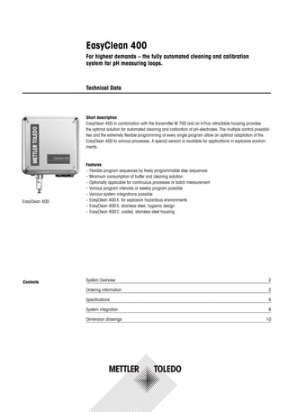
- 1. EasyClean 400 For highest demands – the fully automated cleaning and calibration system for pH measuring loops. Technical Data Contents EasyClean 400 System Overview 2 Ordering information 3 Specifications 4 System integration 8 Dimension drawings 10 Short description EasyClean 400 in combination with the transmitter M 700 and an InTrac retractable housing provides the optimal solution for automated cleaning and calibration of pH-electrodes. The multiple control possibili- ties and the extremely flexible programming of every single program allow an optimal adaptation of the EasyClean 400 to various processes. A special version is available for applications in explosive environ- ments. Features – Flexible program sequences by freely programmable step sequences – Minimum consumption of buffer and cleaning solution – Optionally applicable for continuous processes or batch measurement – Various program intervals or weekly program possible – Various system integrations possible – EasyClean 400X: for explosion hazardous environments – EasyClean 400S: stainless steel, hygienic design – EasyClean 400C: coated, stainless steel housing
- 2. EasyClean 400 automation system The complete automation system always consists of the following components: – EasyClean 400 – Transmitter M 700 with the appropriate module EC 700 – Housing with pneumatic indicators – pH sensor with cable 2 EasyClean 400 System Overview EasyClean 400 The module EC 700 includes the pH measuring module and controls the EC 400. For detailed information about the transmitter M 700, the appropriate InTrac retractable housing, and the respective pH sensor, please refer to the appropriate data sheet. When using a non-glass ISFET pH sensor, an additional pH 2700 module is required. The EasyClean 400 includes the following components: – Basic unit with controller, connections and valves – Media connection, 5 m – Media adapter, 3.5 liter reservoirs (3), assembled with 3 pumps (2 for buffer solution, 1 for cleaning solution) – Connection kit for housing – All connection cables Media adapter with dosing pumps for buffer solution and cleaning agent (3,5 l) Media connetion 5 m (10 m optional) Power in Interconnection cable Pressured air Pressurized water InTrac-Housing and pH-Electrode Transmitter M 700(X)EasyClean 400(X) Distributed control system (DCS)
- 3. 3 Ordering information EasyClean 400 EasyClean 400 Standard devices Type Order no. EasyClean 400, coated EC 400 C 52 403 596 EasyClean 400, coated, Ex EC 400 XC 52 403 597 EasyClean 400, stainless steel EC 400 S 52 403 598 EasyClean 400, stainless steel, Ex EC 400 XS 52 403 599 Transmitter M 700 Modules Type Order no. Module pH and EC 400 EC 700 52 121 259 Module pH and EC 400, Ex EC 700 X 52 121 260 EasyClean 400 Configurator In addition to the 4 standard devices, there is a possibility to configure a device for cases where a 10 m media connection is required or if only 2 pumps are needed. Basic unit* including: Media adapter slot 1: Pump and empty bottle 3.5 l Media adapter slot 2: Pump and empty bottle 3.5 l Accessories Order no. Emergency shut-off switch 52 402 317 Additional external valve Aux 2 52 403 751 Post mounting kit EC 400 52 403 747 Post mounting kit media adapter to EC 400 52 403 750 Spare parts Order no. Media connection 5 m 52 403 724 Media connection 5 m, Ex 52 403 725 Media connection 10 m 52 403 726 Media connection 10 m, Ex 52 403 727 Interface for InTrac 52 403 728 Interface for InTrac, Ex 52 403 729 Pump 52 403 730 Pump, Ex 52 403 731 Media adapter 52 403 732 Media adapter, Ex 52 403 733 Basic unit* Explosion protection N without X ATEX for Ex Zone Housing C stainless steel, coated S stainless steel, polished Media connection 3 5 m hose 4 10 m hose Media adapter slot 3 2 with pumps and empty bottle 3.5 l 0 blank (without pumps and bottle) E C 4 0 0 1 2 3 4 5 6 7 8 9 10
- 4. 4 Specifications EasyClean 400 Pressured air Air quality according to ISO 8573-1 – Particles class class 5 – Water content ... for temperatures ≥15 °C (59 °F): class 4 ... for temperatures 5 ... 15 °C (41…59 °F): class 3 – Oil content class 3 Accept. pressure range 41) ... 10 bar (145 psig) Pressure monitoring Internal automatic monitoring, alarm notification Connection thread 1/4" female Note: For pressured air during operation – as well as for heated outdoor applications applies: temperature range + 5...+ 55 °C (41…131 °F) – for Ex applications + 5 ... + 50 °C (41…122 °F) Flushing water filtered 100 µm Accept. Pressure range 2 ... 6 bar (29…87 psig) temperature range 5 ... 65 °C (41…149 °F) Pressure monitoring Internal automatic monitoring, alarm notification Connection thread 1/4" female / thread 3/4" male Media adapter three plug-in connections for dosing pump Protection class IP 65 Mounting wall or post mounting (optional) Dosing pump for buffer solution or cleaner Bottle 3.5 liters max. Pump height 10 m approx. Feed rate 25 cm3/stroke Level monitoring EC 400 net diagram and NAMUR messages: Maintenance requirements and failure Protection rating IP 65 Wetted parts EPDM, PP, PE, PVDF, Glass, Hastelloy Power Power supply via M 700(X) Module EC 700(X) (EEx ia IIC) 6.8 V (±10 %) / 15 mA Connection Terminals, wire gauge max 2.5 mm2 (furnished connection cable to M 700(X), length 10 m) RS 485 Communication with module M 700(X) and EC 700(X) (EEx ia) or external control computer (e.g. PLC) Transmission 1200 Baud/8 Data Bit/1 Stop Bit/ parity odd Protocol HART® Rev. 5 1) increased minimum pressure 5 bar for probe required in case of high process pressure or difficult process media.
- 5. DCS-input (passive) Measuring/Service Ui = 30 V, potential-free, galvanic isolation up to 60 V Measuring / Service Switching voltage 0 ... 2 V AC/DC inactive (Measuring) (EEx ia IIC) 10 ... 30 V AC/DC active (Service) Connection terminals, wire gauge max. 2.5 mm2 DCS-input (passive) Automatic disabled Ui = 30 V, potential-free, galvanic isolation up to 60 V Auto / Manual Switching voltage 0 ... 2 V AC/DC inactive (EEx ia IIC) (Automatic intervals enabled) 10...30 V AC/DC active (Automatic intervals disabled) Connection terminals, wire gauge max. 2.5 mm2 DCS-inputs (passive) Program start 1 ... 6 Ui = 30 V, potential-free, inter-connected, Bin1 ... 3 galvanic isolation up to 60 V (EEx ia IIC) Switching voltage 0 ... 2 V AC/DC inactive 10 ... 30 V AC/DC active Connection terminals, wire gauge max. 2.5 mm2 DCS-outputs (passive) Program runs, feed-backs program is running, Service, Measuring Service, Measuring electronic switch contacts, potential-free, inter-connected (EEx ia IIC) Ui = 30 V Ii = 100 mA Pi = 800 mW, galvanic isolation up to 60 V Voltage drop < 1.2 V Connection terminals, wire gauge max 2.5 mm2 Explosion protection ATEX II 2(1) GD EEx ia IIC T4 T 70 °C (158 °F) FM Class 1, Divison 1 (pending) EMV DIN EN 61326 Lightning protection DIN EN 61000-4-5, Installation class 2 Protection against according to EN 61010 electric shock Ambient conditions Ambient temperature +5 ... +55 °C (41…131 °F) (Ex: +5 ... +50 °C, 41…122 °F) (different temperature range upon request) transport/storageTemp. -20 ... +70 °C (-4…158 °F) Relative humidity 10 ... 95 %, non-condensing Housing Housing surface S stainless steel A2, polished Housing surface C stainless steel A2, coated Mounting wall or post mounting (optional) Dimensions (W x H x D) approx. 310 mm x 410 mm x 135 mm Protection rating IP 65/NEMA 4X Cable grommets 6 cable glands M20x1.5 Weight approx. 8.5 kg 5 Specifications EasyClean 400
- 6. *) user-defined 1) according to IEC 746 Part 1, at nominal operating conditions 2) ± 1 count, plus sensor error 3) at 20°C, doubles every 10 K 6 Specifications Module EC 700(X) pH/ORP input Simultaneous measurement of pH and ORP (EEx ia IIC) Input glass electrode, Input reference electrode Input redox electrode (ORP) or aux. electrode Measurement range (MR) pH value –2.00…+16.00 ORP value –2000…+2000 mV rH value 0.0…42.5 Permissible voltage ORP + pH [mV] 2000 mV Permissible cable capacitance < 2 nF Glass electrode input1) Input resistance > 1 x 10¹² Ω Input current3) < 1 x 10–12 A Impedance range 0.5…1000 MΩ Reference electrode input1) Input resistance > 1 x 10¹⁰ Ω Input current3) < 1 x 10⁻¹⁰ A Impedance range 0.5…200 kΩ Measurement error2) pH value < 0.02 TC: 0.001 pH/K (display) ORP value < 1 mV TC: 0.05 mV/K Temperature input*) Pt100/Pt1000/NTC 8.55 kΩ/NTC 30 kΩ, (EEx ia IIC) 2-wire connection, adjustable Measurement range –50…+150 °C/–58…+302 °F (Pt100/Pt1000) –20…+150 °C/–4…+302 °F (NTC 30 kΩ) –10…+130 °C/+14…+266 °F (NTC 8.55 kΩ, Mitsubishi) Resolution 0.1 °C/1 °F Measurement error 2) 0.2 % meas. val. + 0.5 K (< 1 K at NTC > 100 °C) Temperature Reference temperature 25 °C compensation – Linear temperature coefficient, user-defined –19.99…+19.99 %/K (media dependent) – Ultrapure water 0…150 °C – Table 0…95 °C, user-defined in 5 K steps Power output For the operation of EasyClean 400 (EEx ia IIC) Uo = +7,2 V Io = 200 mA Ri = 20 Ω Operating data: 6,8 V (±10%)/15 mA ORP*) Automatic conversion to standard hydrogen electrode SHE when type of reference electrode is entered ORP calibration*) Zero adjustment –200…+200 mV Sensocheck Automatic monitoring of glass and reference electrode, can be switched off Sensor monitor Direct display of measured values from sensor for validation pH input/ ORP input/glass electrode impedance/reference electrode impedance/temperature ServiceScope Noise level monitoring of the pH input signal, representation on display Sensoface Provides information on the sensor condition: Zero point/slope, response time, calibration interval, Sensocheck, CalCheck, can be switched off
- 7. 7 Adaptive Automatic adjustment of the calibration interval (Sensoface information) calibration timer*) dependent on the process variables Sensor network diagram Graphic representation of the current sensor parameters in a network diagram on the display: slope, zero point, reference impedance, glass impedance, response time, calibration timer, deviation from calibration range (CalCheck) CalCheck Checks the distance between calibration buffers and measured values. German patent DE 195 36 315 C2 Tolerance band recorder Records zero point and slope of the electrode and the selected tolerance bands, graphical presentation on the display Sensor standardization*) Operating modes – 1-/2-/3-point calibration (best fit line) – Calimatic automatic buffer recognition – Input of individual buffer values – Product calibration – Data entry of pre-measured electrodes Drift check Fine/standard/coarse, adjustable Calimatic buffer sets*) – Fixed buffer sets: 1 METTLER TOLEDO: 2.00/4.01/7.00/9.21 2 Merck/Riedel: 2.00/4.00/7.00/9.00/12.00 3 DIN 19267: 1.09/4.65/6.79/9.23/12.75 4 NIST Standard: 4.006/6.865/9.180 5 Technical buffers to NIST: 1.68/4.00/7.00/10.01/12.46 – Manually selectable buffer set with max. three buffer tables (with option SW 700-002) Nom. zero point*) pH 0…14, admissible span ∆pH = ±1 Nom. slope*) 25…61 mV/pH (25 °C), admissible span 80…103% Vis*) –1000…+1000 mV Calibration protocol/ Recording of: Zero point, slope, Vis, response time, calibration process with date statistics statistics and time of the last three calibrations and the first calibration RS 485 Uo/Ui = +5 V Io/li = 250 mA Ri = 20 Ω (EEx ia IIC) Transfer rate 1200 Bd for EasyClean 400(X) 8 data bits/1 stop bit/no parity Protokoll HART Rev. 5 EasyClean 400(X) Manual, interval and time-controlled activation of calibration and controller rinsing programs Programs 7 programs can be called up – 4 programs with fixed sequences, modifiable – 2 freely configurable programs, 1 service program Diagnostics EasyClean 400(X) network diagram, graphical representation of EasyClean status Maintenance Control of the individual valves and pumps with status indicators Explosion protection see rating plate: KEMA 04 ATEX 2056 (Module EC 700X only) II 2 (1) GD EEx ib [ia] IIC T4 Specifications Module EC 700(X) *) user-defined
- 8. 8 System integration EasyClean 400 Integration with distributed control system The EasyClean 400 and M700 system can be controlled by a distributed control system. Integration with the process control system can be performed either conventionally (digital inputs and outputs) or via a Profibus PA network. Version 1: Conventional (digital inputs and outputs and current outputs) The EasyClean 400 is controlled by the digital inputs and outputs of the distributed control system and the measured values are transmitted via the current outputs of the M 700. In addition, four alarm outputs of the trans- mitter M 700 can be integrated in the process control system. For a description of the inputs and outputs, please refer to specifications. DI DO Current outputs 4…20 mA Interconnection cable Distributed control system (DCS) D
- 9. 9 System integration EasyClean 400 Version 2: Profibus PA The EasyClean 400 is integrated into a distributed control system via a Profibus PA network. This version greatly reduces the wiring requirements, offers an enhanced diagnosis of the measuring point and allows configuration of the system from the control stand. This version requires an additional Profibus PA communication module in the transmitter M 700. Distributed control system (DCS) Profibus DP Coupler/Link Profibus PA Interconnection cable
- 10. 10 Dimension drawings EasyClean 400 Mounting arrangement EasyClean 400(x) and media adapter Arrangement of components: acceptable distances and pump heights. Arrangement of components The installed location must have sufficient stability and must be free of vibration, as much as possible. The specified ambient temperature must be observed and may not fall below +5 °C (41 °F). For outdoor installation, special measures may need to be taken since direct solar radiation may raise the temperature above specified limits. 295 200 800700±250±250 90 max. 300 (left or right) EasyClean 400(X) Media adapter 4x Ø 6,4 2x Ø 8,5 Distances and pump height Cable lengths: EC 400(x) - M 700 (x): 10 m EC 400(X) - Retractable housing: 5 m or 10 m (optional) Max. Pump height of pumps: 10 m Unit of measurement: (mm)
- 11. 11 Dimension drawings EasyClean 400 Unit of measurement: (mm) 410 200 320 135 295 Wall mounting
- 12. 12 Dimension drawings EasyClean 400 EasyClean 400(X) post mounting Hexagon bolts M6x10 (4 pcs) Washers M6 (4 pcs) Washers M6 (4 pcs) Hexagonal nuts M6 (4 pcs) Threaded bolts M6x110 (4pcs) Cap nuts M6 (4 pcs) Vertical or horizontal post mounting Diameter of post: 30...65 mm
- 13. 13 Dimension drawings EasyClean 400 300350 1590 200 8.5 Ø 16 Ø 16 head of bolt 400 Unit of measurement: (mm) Media adapter
- 14. 14 Notes
- 15. 15 Notes
- 16. METTLER TOLEDO Market Organizations Subject to technical changes. © Mettler-Toledo GmbH 08/05 Printed in Switzerland. 52 500 200 Management System certified according to ISO 9001 / ISO 14001 9001 certified ISO 14001 certified ISO Mettler-Toledo GmbH, Process Analytics Industrie Nord, CH-8902 Urdorf Phone +41 44 736 22 11, Fax +41 44 736 26 36 www.mtpro.com Sales and Service: Australia Mettler-Toledo Ltd. 220 Turner Street Port Melbourne AUS-3207 Victoria Phone +61 31300 659 761 Fax +61 3 9645 3935 e-mail mtausprocess@mt.com Austria Mettler-Toledo GmbH Südrandstrasse 17 AT-1230 Wien Phone +43 1 604 19 80 Fax +43 1 604 28 80 e-mail infoprocess.mtat@mt.com Brazil Mettler-Toledo Ind. e Com. Ltda. Alameda Araguaia 451 - Alphaville BR- 06455-000 Barueri/SP Phone +55 11 4166 74 00 Fax +55 11 4166 74 01 e-mail sales@mettler.com.br service@mettler.com.br China Mettler-Toledo Instruments (Shanghai) Co. Ltd. 589 Gui Ping Road Cao He Jing CN-200233 Shanghai Phone +86 21 64 85 04 35 Fax +86 21 64 85 33 51 e-mail mtcs@public.sta.net.cn Croatia Mettler-Toledo d.o.o. Mandlova 3 HR-10000 Zagreb Phone +385 1 292 06 33 Fax +385 1 295 81 40 e-mail mt-zagreb@mt.com Czech Republic Mettler-Toledo spol s.r.o. Trebohosticka 2283/2 CZ-100 00 Praha 10 Phone +420 2 72 123 150 Fax +420 2 72 123 170 e-mail sales.mtcz@mt.com Denmark Mettler-Toledo A/S Naverland 8 DK-2600 Glostrup Phone +45 43 27 08 00 Fax +45 43 27 08 28 e-mail info.mtdk@mt.com France Mettler-Toledo Analyse Industrielle Sarl 30, Boulevard de Douaumont BP 949 F-75829 Paris Cedex 17 Phone +33 1 47 37 06 00 Fax +33 1 47 37 46 26 e-mail mtpro-f@mt.com Germany Mettler-Toledo GmbH Prozeßanalytik Ockerweg 3 D-35396 Gießen Phone +49 641 507 333 Fax +49 641 507 397 e-mail prozess@mt.com Great Britain Mettler-Toledo LTD 64 Boston Road, Beaumont Leys GB-LE4 1AW Leicester Phone +44 116 235 7070 Fax +44 116 236 5500 e-mail enquire.mtuk@mt.com Hungary Mettler-Toledo Kereskedelmi KFT Teve u. 41 HU-1139 Budapest Phone +36 1 288 40 40 Fax +36 1 288 40 50 e-mail mthu@axelero.hu India Mettler-Toledo India Private Limited Amar Hill, Saki Vihar Road Powai IN-400 072 Mumbai Phone +91 22 2857 0808 Fax +91 22 2857 5071 e-mail sales.mtin@mt.com Italy Mettler-Toledo S.p.A. Via Vialba 42 I-20026 Novate Milanese Phone +39 02 333 321 Fax +39 02 356 2973 e-mail customercare.italia@mt.com Japan Mettler-Toledo K.K. Process Division 5F Tokyo Ryutsu Center, Annex B 6-1-1 Heiwajima, Ohta-ku JP-143-0006 Tokyo Phone +81 3 5762 07 06 Fax +81 3 5762 09 71 e-mail helpdesk.ing.jp@mt.com Malaysia Mettler-Toledo (M) Sdn Bhd Bangunan Electroscon Holding Lot 8 Jalan Astaka U8/84 Seksyen U8, Bukit Jelutong MY-40150 Shah Alam Selangor Malaysia Phone +60 3 78 45 57 73 Fax +60 3 78 45 87 73 e-mail ahmad.rashidi@mt.com Mexico Mettler-Toledo S.A. de C.V. Pino No. 350, Col. Sta. MA. Insurgentes, Col Atlampa MX- 06450 México D.F. Phone +52 55 55 47 57 00 Fax +52 55 55 41 22 28 e-mail mario.roca@mt.com Poland Mettler-Toledo (Poland) Sp.z.o.o. ul. Poleczki 21 PL- 02-822 Warszawa Phone +48 22 545 06 80 Fax +48 22 545 06 88 e-mail polska@mt.com Russia Mettler-Toledo Vostok ZAO Sretenskij Bulvar 6/1 Office 6 RU-101000 Moscow Phone +7 095 921 92 11 Fax +7 095 921 63 53 +7 095 921 78 68 e-mail inforus@mt.com Singapore Mettler-Toledo (S) Pte. Ltd. Block 28 Ayer Rajah Crescent #05-01 SG-139959 Singapore Phone +65 6890 00 11 Fax +65 6890 00 12 +65 6890 00 13 e-mail ashley.kong@mt.com Slovakia Mettler-Toledo s.r.o. Bulharska 61 SK-82104 Bratislava Phone +421 243 42 74 96 Fax +421 243 33 71 90 e-mail predaj@mt.com Slovenia Mettler-Toledo d.o.o. Peske 12 SI-1236 Trzin Phone +386 1 530 80 50 Fax +386 1 562 17 89 e-mail cipot@mtslo.mt.com racman@mettler-toledo.si South Korea Mettler-Toledo (Korea) Ltd. Yeil Building 1 & 2 F 124-5, YangJe-Dong SeCho-Ku KR-137-130 Seoul Phone +82 2 3498 3500 Fax +82 2 3498 3556 e-mail Sales_MTKR@mt.com Spain Mettler-Toledo S.A.E. C/ Miguel Hernández, 69-71 ES - 08908 L’Hospitalet de Llobregat (Barcelona) Phone +34 93 223 76 00 Fax +34 93 223 76 01 e-mail bcn.centralita@mt.com Sweden Mettler-Toledo AB Virkesvägen 10 Box 92161 SE-12008 Stockholm Phone +46 8 702 50 00 Fax +46 8 642 45 62 e-mail sales.mts@mt.com Switzerland Mettler-Toledo (Schweiz) AG Im Langacher Postfach CH- 8606 Greifensee Phone +41 44 944 45 45 Fax +41 44 944 45 10 e-mail info.ch@mt.com info.ola.ch@mt.com Thailand Mettler-Toledo (Thailand) Ltd. 272 Soi Soonvijai 4 Rama 9 Rd., Bangkapi Huay Kwang TH-10320 Bangkok Phone +66 2 723 03 00 Fax +66 2 719 64 79 e-mail mettler@samart.co.th USA/Canada Mettler-Toledo Ingold, Inc. 36 Middlesex Turnpike Bedford, MA 01730, USA Phone +1 781 301 8800 Toll free +1 800 352 8763 Fax +1 781 271 0681 e-mail mtprous@mt.com ingold@mt.com