More Related Content Similar to UKWP Case study - Mauchline Final copy 23 06 15 (20) 1. May 2015 • Mauchline STW • DfMA • UK Water Projects 1/8
Mauchline STW
Fully Innovative Design for Manufacture & Assembly (DfMA) approach to new assets
by Richard Daly BEng (Hons) Civil Engineering & Msc Construction Management
Senior Project Manager for Expanded Ltd
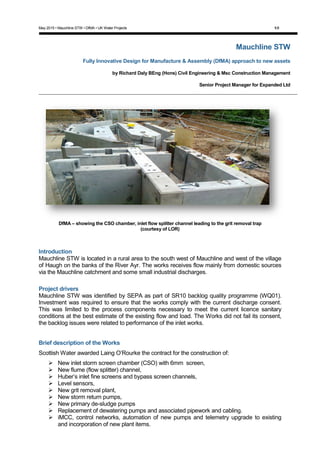
DfMA – showing the CSO chamber, inlet flow splitter channel leading to the grit removal trap
(courtesy of LOR)
Introduction
Mauchline STW is located in a rural area to the south west of Mauchline and west of the village
of Haugh on the banks of the River Ayr. The works receives flow mainly from domestic sources
via the Mauchline catchment and some small industrial discharges.
Project drivers
Mauchline STW was identified by SEPA as part of SR10 backlog quality programme (WQ01).
Investment was required to ensure that the works comply with the current discharge consent.
This was limited to the process components necessary to meet the current licence sanitary
conditions at the best estimate of the existing flow and load. The Works did not fail its consent,
the backlog issues were related to performance of the inlet works.
Brief description of the Works
Scottish Water awarded Laing O’Rourke the contract for the construction of:
New inlet storm screen chamber (CSO) with 6mm screen,
New flume (flow splitter) channel,
Huber’s inlet fine screens and bypass screen channels,
Level sensors,
New grit removal plant,
New storm return pumps,
New primary de-sludge pumps
Replacement of dewatering pumps and associated pipework and cabling.
iMCC, control networks, automation of new pumps and telemetry upgrade to existing
and incorporation of new plant items.
2. May 2015 • Mauchline STW • DfMA • UK Water Projects 2/8
Mauchline STW
© Laing O’Rourke 2015, all rights reserved
Figure 1 - Mauchline STW site layout – courtesy of Jacobs
Design flow
The current estimate of contributing population equivelant (PE) is 6,000, using average flow
per head of 157 l/head/day and a design infiltration rate assessed at 505m3/day (i.e. 55.0%
of PG). Using these parameters, the design Dry Weather Flow (DWF) is assessed as 1,462
m3/d. The CAR Licence Dry Weather Flow has not to exceed 1,364 m3/d.
3. May 2015 • Mauchline STW • DfMA • UK Water Projects 3/8
Mauchline STW
© Expanded 2014, all rights reserved
Overview of treatment works process
The inlet works consist of a CSO chamber, an open channel inlet screening system with
2no. fine screens and a grit removal plant, designed to receive 110l/s and pass forward flows
of 95l/s to PSTs for further treatment. An inlet flow control modulating penstock is provided
at the outlet of the CSO chamber to pass forward all the incoming flows below 110l/s to the
inlet screening channel and divert excess flows to the storm tank via a 6mm weir-mounted
screen. The treatment works also contains a storm storage tank, primary treatment
consisting of PSTs, secondary treatment including an aeration tank and a FST, trickling
filters and humus tanks. The final effluent discharges to the River Ayr through an outfall at
the west end of the Works. Flows up to 3 x DWF pass forward to full treatment, flows above
3 x DWF overflow at the 6DWF and 3DWF weirs routed to the storm tank.
Electrical supply
A 415V 3Phase supply is laid underground to the main control pump house. Electricity is
supplied to all plant equipment from here and can be operated locally. The main incoming supply
from Scottish Power is located in the switch room electrical mains building at the top side of the
works. In 2014, a new 400v, TPN, 50HZ iMCC / main switchboard was installed by Laing
O’Rourke at the top of the works to power the new inlet works, as well as to back feed the
existing switch room to supply the rest of the site.
Logistics
The primary challenge on the Mauchline site was logistics and the lack of storage areas, as it is
located at the bottom of a valley, with hilly access and egress. Therefore a “just-in-time”
approach was implemented to mitigate any risk and Laing O’Rourke opted to design the new
inlet works using a Design for Manufacture & Assembly (DfMA) approach.
Delivery approach
Laing O’Rourke and Scottish Water worked together with the DfMA design and construction
approach enabling the design phase to be agreed much earlier. Therefore reducing the
programme and reducing onsite working-hours. This made the construction inherently safer and
reduced the site carbon footprint through the early involvement in design allowing us to drive out
raw material wastage from the outset, while maximising recycling throughout the manufacturing
process.
The DfMA solid wall construction components for the Combined Sewer Overflow (CSO)
chamber, geometric blocks to form the flow splitter channel, solid slab and wall construction for
the grit removal trap, with a conical base section, greatly reducing the need for onsite shuttering
and steel fixing activities and reduced requirement for working space excavations which was key
given the logistic of the site and the relatively narrow strip of ground between the upper and
lower tier of the site at which the majority of works took place.
4. May 2015 • Mauchline STW • DfMA • UK Water Projects 4/8
Mauchline STW
© Expanded 2014, all rights reserved
Figure 2 - New inlet works precast details (courtesy of Bison Manufacturing ltd.)
The use of Digital Engineering on the project enabled the staff and workforce to visualise the
more complex elements of the works and analyse, pre construction, where interface issues may
have arisen and where developing connection details needed to be focused upon. The model
allowed the site to carry out pre-construction checks of each section of the works, for
compatibility of the package plant items supplied by Scottish Water frame work contractors and
facilitated early detection of clashes and dimensional discrepancies.
This allowed the site to initiate changes and interventions in the virtual world rather than costly
and time consuming reworking and procurement route delays also promoting steel working sub
contractor early involvement i.e. grills, steps, hand rails and secondary steel work.
Sections through and rotational virtual tours were also incorporated in to visual task sheets to
promote safe, right first time construction.
Figure 3 - Digital Engineering model of the DfMA sections used in the construction at Mauchline STW
(courtesy of Laing O’Rourke)
5. May 2015 • Mauchline STW • DfMA • UK Water Projects 5/8
Mauchline STW
© Expanded 2014, all rights reserved
Construction phase
The CSO chamber was constructed using solid wall
components (See photos 1 & 2) complete with pull out bars for
connection to the inlet channel walls, supplied by Bison
manufacturing ltd. As a result these were erected in a much
shorter period, using a crane to lift the walls into position onto
the previously poured insitu concrete base slab. Corner
joints/junctions had full height dowel bar (H12), inside a
Pfiefer VS PLUS box, 20mm nominal joint filled with
Thixotropic joint filler to seal the joints.
The downstream external facing wall incorporated pull out
bars (H12’s @150mm centres) to tie into the flume channel
formed immediately downstream of the CSO.
Photo 1 - DfMA solid wall construction CSO
to house hydrok screen (courtesy of LOR)
Photo 2 - Completed CSO (courtesy of LOR)
The inlet flume channel (See Photo 3) was formed insitu with a
preformed stainless steel flume former incorporated to ensure
dimensional and cross sectional accuracy.
Photo 3 - Completed Inlet Flue Channel,
leading to the flow splitter (courtesy of
LOR)
The main body of the works, (See photos 4-8) the inlet channel
outer walls, flow splitter channels and screen bases were
formed using complex geometric blocks.
The inlet channel outer walls were positioned, lined and
levelled, dowelled and grouted to form structural tie in detail
for incorporation into the insitu concrete base which overlaid
the horizontal leg of the precast L-shaped section of the
retaining walls. This base in turn supported the DfMA flow
splitter blocks. Photo 4 - DfMA – Pre cast showing the
Inlet flow splitter channel outer walls
(courtesy of LOR)
The geometric flow splitter blocks, complete with rebates for
penstocks and incorporating Wells Tube voids to take 63mm
dowel bars to tie the structure together vertically, were then
craned into position. Using the same detail as the CSO for
filling the external wall joints. The flow splitter structure was
formed in 4no. layers at 300mm thick sitting on levelling
shims and grouted with non shrink, free flowing grout.
Photo 5 - Installation of the flow splitter
channel (courtesy of LOR)
6. May 2015 • Mauchline STW • DfMA • UK Water Projects 6/8
Mauchline STW
© Expanded 2014, all rights reserved
Photo 6 - DfMA – Flow splitter channel installation
(courtesy of LOR)
Photo 7 - Installation of the flow
splitter blocks (courtesy of LOR)
Photo 8 - Inlet works geometric flow splitter channel
complete with penstocks (courtesy of LOR)
The final section of DfMA was the assembly of the precast
base slabs complete with starter bars, profiled walls and
circular chamber complete with conical deepening for the grit
removal plant. (See photos 9-10). These components were
supplied by a specialist precast supplier and had rebates,
recesses and penetrations preformed to obtain the level of
accuracy and uniformity required to position the package
plant from Ovivo, slot in the penstocks and achieve planned
tie in to the adjacent structural elements.
The overall inlet works construction was completed by casting
insitu stitch wall sections between the CSO, flume channel,
flow splitter walls and channels and the GRP.
Photo 9 - Precast solid wall and base slab, used to form grit removal trap
(courtesy of LOR)
Photo 10 - DfMA solid base slab
for the grit removal trap (courtesy
of LOR)
7. May 2015 • Mauchline STW • DfMA • UK Water Projects 7/8
Mauchline STW
© Expanded 2014, all rights reserved
Conclusion
The project gained Capex 3 approval in October 2012 and construction started in December
2013 by Scottish Water Solutions’ (SWS) in-house delivery partners, Expanded, CHt and
Jacobs. The project was completed in March 2015 and was signed off by Scottish Water with
plant acceptance in April 2015. The total investment was in the region of £3.1m.
Client quote
‘The successful completion of this project demonstrates the importance of good relationship
building between all stakeholders’ – Jim Clarke – Scottish Water Solutions.
The Author would like to thank Scottish Water, Scottish Water solutions, Expanded, Jacobs,
Crown House Technologies and Bison Manufacturing Ltd. for their assistance in this paper.
Photo 11 - Image of the completed new inlet works at Mauchline (courtesy of LOR)
8. May 2015 • Mauchline STW • DfMA • UK Water Projects 8/8
Mauchline STW
© Expanded 2014, all rights reserved
Additional Site Photos
Photo 12 - Installation of the flow splitter blocks
(courtesy of LOR)
Photo 13 - Inlet works geometric flow splitter channel complete
with penstocks (courtesy of LOR)
Photo 14 - Precast solid wall and base slab, used to
form grit removal trap (courtesy of LOR)
Photo 15 - DfMA solid base slab for the grit removal trap
(courtesy of LOR)
Photo 16 - New grit removal plant, iMCC & washwater
kiosk (courtesy of LOR)
Photo 17 - Reforming of the desludge well (courtesy of LOR)