SlideShare a Scribd company logo
1 of 126
Direct energy conversion (DEC) or
simply direct conversion converts a
charged particle's kinetic energy into
a voltage. It is a scheme for power
extraction from nuclear fusion
Thermo electric power generation
Thermo ionic power generation
Magneto hydro dynamic systems
Photovoltaic power systems
Fuel cells
Thermo nuclear fusion power generation
The pioneer in thermoelectric was a German scientist
Thomas Johann Seebeck (1770-1831)
Thermoelectricity refers to a class of phenomena in
which a temperature difference creates an electric
potential or an electric potential creates a
temperature difference.
Thermoelectric power generator is a device that
converts the heat energy into electrical energy based
on the principles of Seebeck effect
Later, In 1834, French scientist, Peltier and in 1851,
Thomson (later Lord Kelvin) described the thermal
effects on conductors
 In the purer metallic conductors outer electrons, less
connected to others, can move freely around all the
material, as if they do not belong to any atom. These
electrons transmit energy one to another through
temperature variation, and this energy intensity varies
depending on the nature of the material.
 If two distinct materials are placed in contact, free
electrons will be transferred from the more “loaded”
material to the other, so they equate themselves, such
transference creates a potential difference, called contact
potential, since the result will be a pole negatively
charged by the received electrons and another positively
charged by the loss of electrons.
When the junctions of two different metals are maintained
at different temperature, the emf is produced in the
circuit. This is known as Seebeck effect.
The material A is maintained at T+∆T
temperature
The material B is maintained at
temperature ‘T’.
Since the junctions are maintained at
different temperature, the emf ‘V’ flows
across the circuit.
• The electric potential produced by a temperature
difference is known as the Seebeck effect
and the proportionality constant is called the
Seebeck coefficient.
• If the free charges are positive (the material is p-
type), positive charge will build up on the
cold which will have a positive potential.
• Similarly, negative free charges (n-type material)
will produce a negative potential at the cold end.
Whenever current passes
through the circuit of two
dissimilar conductors,
depending on the current
direction, either heat is
absorbed or released at the
junction of the two conductors.
This is known as Peltier effect.
Irreversible conversion of electrical energy
into heat when a current I flows through a
ressistance R.

Qj=I2R
 Thermoelectric power generation (TEG) devices
typically use special semiconductor materials, which
are optimized for the Seebeck effect.
 The simplest thermoelectric power generator
consists of a thermocouple, comprising a p-type and
n-type material connected electrically in series and
thermally in parallel.
 Heat is applied into one side of the couple and
rejected from the opposite side.
 An electrical current is produced, proportional to the
temperature gradient between the hot and cold
junctions.
 Therefore, for any TEPG, there are four basic component required
such as
• Heat source (fuel)
• P and N type semiconductor stack (TE module)
• Heat sink (cold side)
• Electrical load (output voltage)
• As the heat moves from hot side to cold side, the
charge carrier moves in the semiconductor materials
and hence the potential deference is created.
• The electrons are the charge carriers in the case of N-
type semiconductor and Hole are in P-type
semiconductors.
• In a stack, number of P-type and N-type
semiconductors is connected.
• A single PN connection can produce a Seebeck
voltage of 40 mV.
• The heat source such as natural gas or propane are
used for remote power generation
Power P= I2RL V=IR
I= V/R =
P max = (when R=RL) =
Figure of merit
Z=
L
L
s
R
RR
T
P
2
12

















 

R
T
P s
4
22
12
 








R
s
2
12
 Max. Ideal efficiency
where: w is the power
delivered to the
external load and qH is
the positive heat flow
from source to sink















 

hcm
m
h
ch
TTZT
ZT
T
TT
/1
11
max
KR
Z
2
21 )(  

2
)( ch
m
TT
T


RITKIT
RI
q
w
h
l
h
2
21
2
5.0)( 



lRR
T
I



)( 21 
R
R
m l

22/1
22
2/1
11
2
21
])/()/[(
)(


kk
Z



Energy provided to the load
Heat energy absorbed at the hot junctionEfficiency of the generator =


k
kKR 
l
kA
K
)(

A
l
R
)(

Figure of merit
 A high electrical conductivity is necessary to minimize
Joule heating and low thermal conductivity helps to retain
heat at the junctions and maintain a large temperature
gradient. A large Seebeck coefficient is advicable.These
three properties were later put together and it is called
figure-of-merit (Z).
• The good thermoelectric materials should possess
1. Large Seebeck coefficients
2. High electrical conductivity
3. Low thermal conductivity

• The example for thermoelectric materials
• BismuthTelluride (Bi2Te3),
• Lead Telluride (PbTe),
• SiliconGermanium (SiGe),
• Bismuth-Antimony (Bi-Sb)
• Easy maintenance: They works electrically without any moving parts so
they are virtually maintenance free.
• Environment friendly: Thermoelectric generators produce no
pollution. Therefore they are eco friendly generators.
• Compact and less weight: The overall thermoelectric cooling system
is much smaller and lighter than a comparable mechanical system.
• High Reliability: Thermoelectric modules exhibit very high reliability
due to their solid-state construction
• No noise: They can be used in any orientation and in zero gravity
environments. Thus they are popular in many aerospace
applications.
• Convenient Power Supply: They operate directly from a DC
power source.
31
Water/Beer Cooler
Cooled
Car Seat
Electronic Cooling
Cryogenic IR Night Vision
Laser/OE Cooling
TE
Si bench
 The standard material we work with is BiTe. The best
efficiency that can be achieved with this material is
approximately 6%.
 But once the material is constructed into a module, efficiency
drops to 3 to 4% because of thermal and electrical impedance.
No other semiconductor material can perform as well as BiTe
as far as efficiency is concerned. Other material such as PbTe
are used but are far less efficient, and must be used at
significantly higher temperatures (450°C- 600°C) hot side and
are not commercially available!
 Thermoelectric Seebeck effect modules are designed for very
high power densities, on the order of 50 times greater than
Solar PV!
 Bismuth telluride is the best bulk TE material with ZT=1
 Trends in TE devices:
• Superlattices and nanowires: Increase in S, reduction in k
• Nonequilibrium effects: decoupling of electron and phonon
transport
• Bulk nanomaterial synthesis
 Trends in TE systems
• Microrefrigeration based on thin film technologies
• Automobile refrigeration
• TE combined with fluidics for better heat exchangers
 To match a refrigerator, an effective ZT= 4 is needed
 To efficiently recover waste heat from car, ZT = 2 is
needed
 Thermionic emission is the basis for the working
of this system.
 In 1873, the Britain professor Frederic Guthrie
invented the Thermionic phenomenon.
 In 1883, Thomas A. Edison observed that the
electrons are emitted from a metal surface when
it was heated. This effect is called Edison effect.
 Later in 1904, a British physicist John Ambrose
Fleming developed two-element vacuum tube
known as diode.
 Thermionic power generator (TPG) is a static
device that converts heat energy into electrical
energy by boiling electrons from a hot emitter
surface (= 1800K) across a small inter electrode
gap (< 0.5 mm) to a cooler collector surface (=
1000K)

The idea of electrons leaving the surface
• A thermionic energy converter (or) thermionic power
generator is a device consisting of two electrodes placed
near one another in a vacuum.
• One electrode is normally called the cathode, or emitter,
and the other is called the anode, or plate.
• Ordinarily, electrons in the cathode are prevented from
escaping from the surface by a potential-energy barrier.
• When an electron starts to move away from the surface,
it induces a corresponding positive charge in the
material, which tends to pull it back into the surface.
• To escape, the electron must somehow acquire enough
energy to overcome this energy barrier.
• At ordinary temperatures, almost none of the electrons
can acquire enough energy to escape.
• However, when the cathode is very hot, the electron
energies are greatly increased by thermal motion.
• At sufficiently high temperatures, a considerable number of
electrons are able to escape.
• The liberation of electrons from a hot surface is
called thermionic emission
 For the electrons to travel, the unit is at vacuum. This
limit the size of the generator.
 Electron emission is inhibited by space charge, small
quantity of Cesium metal is introduced into the evacuated
vessel
 Molybdenum, tantalum, tungsten impregnated barium
oxide.Uranium carbide, zirconium carbide.
 Prototype combustion-heated thermionic systems for
domestic heat and electric power cogeneration
 Advantages
• Higher efficiency and high power density
• Compact to use
 Disadvantages
• There is a possibility of vaporization of
emitter surface
• Thermal breaking is possible during
operation
• The sealing is often gets failure
An MHD generator is a device for
converting heat energy of a fuel directly
into electrical energy without conventional
electric generator.
 In advanced countries MHD generators are widely used but in
developing countries like INDIA, it is still under construction, this
construction work in in progress at TRICHI in TAMIL NADU, under
the joint efforts of BARC (Bhabha atomic research center),
Associated cement corporation (ACC) and Russian technologists.
Magneto hydrodynamics (MHD)
(magneto fluid dynamics or hydro
magnetics) is the academic
discipline which studies the dynamics of
electrically conducting fluids.
Examples of such fluids include plasmas,
liquid metals, and salt water. The
word magneto hydro dynamics (MHD) is
derived from magneto-
meaning magnetic field, and hydro-
meaning liquid, and -dynamics meaning
movement. The field of MHD was
initiated by Hannes Alfvén , for which he
received the Nobel Prize in Physics in
1970 Hannes Alfvén
 This effect is a result of FARADAYS LAWS OF ELECTRO
MAGNETIC INDUCTION. (i.e. when the conductor moves through a
magnetic field, it generates an electric field perpendicular to the
magnetic field & direction of conductor).
The induced EMF is given by
Eind = u x B
where u = velocity of the conductor.
B = magnetic field intensity.
The induced current is given by,
Iind = C x Eind
where C = electric conductivity
The retarding force on the conductor is the Lorentz force given by
Find = Iind X B
 The conducting fluid flow is forced between the plates
with a kinetic energy and pressure differential sufficient
to over come the magnetic induction force Find.
 An ionized gas is employed as the conducting fluid.
 Ionization is produced either by thermal means I.e. by
an elevated temperature or by seeding with substance
like cesium or potassium vapors which ionizes at
relatively low temperatures.
 The atoms of seed element split off electrons. The
presence of the negatively charged electrons makes
the gas an electrical conductor.
90% conductivity can be
achieved with a fairly low degree
of ionization of only about 1%.
Open cycle MHD
Closed cycle MHD
Seeded Inert gas system.
Liquid metal system
 Temperature of CC MHD plants is very
less compared to OC MHD plants. It’s
about 1400oC.
 The fuel used maybe oil through an oil tank or gasified
coal through a coal gasification plant
 The fuel (coal, oil or natural gas) is burnt in the
combustor or combustion chamber.
 The hot gases from combustor is then seeded with a
small amount of ionized alkali metal (cesium or
potassium) to increase the electrical conductivity of the
gas.
 The seed material, generally potassium carbonate is
injected into the combustion chamber, the potassium is
then ionized by the hot combustion gases at
temperature of roughly 2300’ c to 2700’c.
 To attain such high temperatures, the compressed air is used
to burn the coal in the combustion chamber, must be adequate
to at least 11000c.
 A lower preheat temperature would be adequate if the air is
enriched in oxygen. An alternative is used to compress oxygen
alone for combustion of fuel, little or no preheating is then
required. The additional cost of oxygen might be balanced by
saving on the preheater.
 The hot pressurized working fluid leaving the combustor flows
through a convergent divergent nozzle. In passing through the
nozzle, the random motion energy of the molecules in the hot
gas is largely converted into directed, mass of energy. Thus ,
the gas emerges from the nozzle and enters the MHD
generator unit at a high velocity.
 In a closed cycle system the carrier gas operates in the form
of Brayton cycle. In a closed cycle system the gas is
compressed and heat is supplied by the source, at essentially
constant pressure, the compressed gas then expands in the
MHD generator, and its pressure and temperature fall. After
leaving this generator heat is removed from the gas by a
cooler, this is the heat rejection stage of the cycle. Finally the
gas is recompressed and returned for reheating.
 The complete system has three distinct but interlocking loops.
On the left is the external heating loop. Coal is gasified and
the gas is burnt in the combustor to provide heat. In the
primary heat exchanger, this heat is transferred to a carrier
gas argon or helium of the MHD cycle. The combustion
products after passing through the air preheater and purifier
are discharged to atmosphere.
 Because the combustion system is separate from the
working fluid, so also are the ash and flue gases.
Hence the problem of extracting the seed material from
fly ash does not arise. The flue gases are used to
preheat the incoming combustion air and then treated
for fly ash and sulfur dioxide removal, if necessary
prior to discharge through a stack to the atmosphere.
 The loop in the center is the MHD loop. The hot argon
gas is seeded with cesium and resulting working fluid
is passed through the MHD generator at high speed.
The dc power out of MHD generator is converted in ac
by the inverter and is then fed to the grid.
 When a liquid metal provides the electrical conductivity, it is
called a liquid metal MHD system.
 An inert gas is a convenient carrier
 The carrier gas is pressurized and heated by passage through
a heat exchanger within combustion chamber. The hot gas is
then incorporated into the liquid metal usually hot sodium to
form the working fluid. The latter then consists of gas bubbles
uniformly dispersed in an approximately equal volume of liquid
sodium.
 The working fluid is introduced into the MHD generator
through a nozzle in the usual ways. The carrier gas then
provides the required high direct velocity of the electrical
conductor.
 After passage through the generator, the liquid metal is
separated from the carrier gas. Part of the heat exchanger to
produce steam for operating a turbine generator. Finally the
carrier gas is cooled, compressed and returned to the
combustion chamber for reheating and mixing with the
recovered liquid metal. The working fluid temperature is
usually around 800’c as the boiling point of sodium even under
moderate pressure is below 900’c.
 At lower operating temp, the other MHD conversion systems
may be advantageous from the material standpoint, but the
maximum thermal efficiency is lower. A possible compromise
might be to use liquid lithium, with a boiling point near 1300’c
as the electrical conductor lithium is much more expensive
than sodium, but losses in a closed system are less.
 It has no moving parts & the actual conductors are replaced
by ionized gas (plasma). The magnets used can be
electromagnets or superconducting magnets.
 The plasma temperature is typically over 2000 °C, the duct
containing the plasma must be constructed from non-
conducting materials capable of withstanding this high
temperature. The electrodes must of course be conducting as
well as heat resistant.
 Superconducting magnets of 4~6Tesla are used. Here
exhaust gases are again recycled & the capacities of
these plants are more than 200MW.
 Non-conducting walls of the channel must be constructed
from an exceedingly heat-resistant substance such as
yttrium oxide or zirconium dioxide to retard oxidation
 Ionization of GAS:
 Various methods for ionizing the gas are available, all of
which depend on imparting sufficient energy to the gas. The
ionization can be produced by thermal or nuclear means.
Materials such as Potassium carbonate or Cesium are often
added in small amounts, typically about 1% of the total mass
flow to increase the ionization and improve the conductivity,
particularly combustion of gas plasma
 In MHD the thermal pollution of water is eliminated. (Clean Energy
System)
 Use of MHD plant operating in conjunction with a gas turbine power
plant might not require to reject any heat to cooling water.
 These are less complicated than the conventional generators,
having simple technology.
 There are no moving parts in generator which reduces the energy
loss.
 These plants have the potential to raise the conversion efficiency up
to 55-60%. Since conductivity of plasma is very high (can be treated
as infinity).
 It is applicable with all kind of heat source like nuclear, thermal,
thermonuclear plants etc. Extensive use of MHD can help in better
fuel utilization.
 The construction of superconducting magnets for small MHD
plants of more than 1kW electrical capacity is only on the
drawing board.
 Difficulties may arise from the exposure of metal surface to
the intense heat of the generator and form the corrosion of
metals and electrodes.
 Construction of generator is uneconomical due to its high
cost.
 Construction of Heat resistant and non conducting ducts of
generator & large superconducting magnets is difficult.
 MHD without superconducting magnets is less efficient when
compared with combined gas cycle turbine.
PhotovoltaicTheory
p-Silicon
n-Silicon
+ + + + + + + + + +
+ + + + + + + +
- - - - - - - - - -
PV System’s Components
Solar Array
Storage Batteries
Charge Controller (Regulator)
Inverter (For AC Systems Only)
Photovoltaic System
Battery
PV
Array
Charge Controller
PV System’s Components
Load
Photovoltaic
Array
Battery Bank
Inverter
(AC loads)
Charge Controller
Design Strategy
PV Array:
Type Selection
Sizing
Climate & Geographical Location
Considerations
Design Strategy
PV Array Types:
Type Efficiency Cost Economical
Feasibility
Crystalline
Silicon (c-Si)
High
15-24%
High Low
Single
Junction
Low
5-10%
Low Medium
Amorphous
Silicon (a-Si)
Multi-
Junction
Medium
7.5-13%
Low High
Design Strategy
PV Array Sizing:
De-rating Factors
 Aging 20%
 Dirt Accumulation 20%
 Future Growth 10%
Recharging Period 4 days
System Voltage
Load Profile
Design Strategy
PV Array Climate &
Geographical Location:
 Solar Insolation (Radiation)
 Effective Sun Hours
 Array Orientation
 Direction (Toward South)
 Tilt Angle
 Fixed Angle (Latitude + 10 Degrees)
 Adjustable (Sun Tracking)
Sun Insolation
5.0 kW/m2
/day
5.0
Photovoltaic Arrays Field
Design Strategy
Storage Battery:
Type Selection
Sizing
Environment Considerations
Design Strategy
Storage Battery:
Type Selection (cyclic application)
Tubular Plate Lead-Acid
Pocket Plate Nickel-Cadmium
System Voltage
Load Profile
Backup Time (Autonomy) 7 days
De-rating Factors Lead-Acid Ni-Cad
Aging 25% 10%
Temp. Compensation 19% 14%
Design 10% 10%
Design Strategy
Storage Battery:
Sizing
No Temperature Control  Temp. Compensation
Outdoor Battery Enclosure
Shade Requirement
Design Strategy
Storage Battery:
Environment Considerations
Design Strategy
Charge Regulator:
 Type Selection
 Single Stage
 Multistage
 Sizing (Array Rated Currents)
 Temperature Compensation
 Lead-Acid -5mV/oC/cell
 Ni-Cad -3mV/oC/cell
 Low Voltage Disconnect
 Lead-Acid 1.85V/cell
 Ni-Cad 1.15V/cell
Applications
Cathodic Protection Systems
Telecommunications Systems
SCADA Systems
Offshore Platforms
Highway Lighting
Remote Homes
Irrigation Water Pumping
Advantages
Reliable
No Fuels
Low Maintenance
Long-term Savings
No Pollution
No Noise
$ $ $
Disadvantages
High Initial Cost (3-10 times)
Specialized Maintenance
 Batteries
 Power Conditioning Equipment
Large Space
$
$
$
$
$ $
Fuel Cells
The Promise of Fuel Cells
• “A score of nonutility companies are
well advanced toward developing a
powerful chemical fuel cell, which
could sit in some hidden closet of
every home silently ticking off
electric power.”
• Theodore Levitt, “Marketing Myopia,” Harvard
Business Review, 1960
Theodore Levitt, “Marketing Myopia,” Harvard Business Review, 1960
Parts of a Fuel Cell
• Anode
• Negative post of the fuel cell.
• Conducts the electrons that are freed from the hydrogen molecules so that
they can be used in an external circuit.
• Etched channels disperse hydrogen gas over the surface of catalyst.
• Cathode
• Positive post of the fuel cell
• Etched channels distribute oxygen to the surface of the catalyst.
• Conducts electrons back from the external circuit to the catalyst
• Recombine with the hydrogen ions and oxygen to form water.
• Electrolyte
• Proton exchange membrane.
• Specially treated material, only conducts positively charged ions.
• Membrane blocks electrons.
• Catalyst
• Special material that facilitates reaction of oxygen and hydrogen
• Usually platinum powder very thinly coated onto carbon paper or cloth.
• Rough & porous maximizes surface area exposed to hydrogen or oxygen
• The platinum-coated side of the catalyst faces the PEM.
Fuel Cell Operation
• Pressurized hydrogen gas (H2) enters cell on
anode side.
• Gas is forced through catalyst by pressure.
• When H2 molecule comes contacts platinum catalyst, it
splits into two H+ ions and two electrons (e-).
• Electrons are conducted through the anode
• Make their way through the external circuit (doing useful
work such as turning a motor) and return to the cathode
side of the fuel cell.
• On the cathode side, oxygen gas (O2) is forced
through the catalyst
• Forms two oxygen atoms, each with a strong negative
charge.
• Negative charge attracts the two H+ ions through the
membrane,
• Combine with an oxygen atom and two electrons from
the external circuit to form a water molecule (H2O).
PEM Fuel Cell Schematic
Proton-Exchange Membrane Cell
http://www.news.cornell.edu/releases/Nov03/Fuelcell.institute.deb.html
Fuel Cell Stack
http://www.nrel.gov/hydrogen/photos.html
Hydrogen Fuel Cell Efficiency
• 40% efficiency converting methanol to
hydrogen in reformer
• 80% of hydrogen energy content
converted to electrical energy
• 80% efficiency for inverter/motor
• Converts electrical to mechanical energy
• Overall efficiency of 24-32%
Auto Power Efficiency Comparison
Technology
System
Efficiency
Fuel Cell 24-32%
Electric Battery 26%
Gasoline Engine 20%
http://www.howstuffworks.com/fuel-cell.htm/printable
Fuel Cell Energy Exchange
http://hyperphysics.phy-astr.gsu.edu/hbase/thermo/electrol.html
Other Types of Fuel Cells
• Alkaline fuel cell (AFC)
• This is one of the oldest designs. It has been used in the U.S. space program
since the 1960s. The AFC is very susceptible to contamination, so it requires
pure hydrogen and oxygen. It is also very expensive, so this type of fuel cell is
unlikely to be commercialized.
• Phosphoric-acid fuel cell (PAFC)
• The phosphoric-acid fuel cell has potential for use in small stationary power-
generation systems. It operates at a higher temperature than PEM fuel cells,
so it has a longer warm-up time. This makes it unsuitable for use in cars.
• Solid oxide fuel cell (SOFC)
• These fuel cells are best suited for large-scale stationary power generators
that could provide electricity for factories or towns. This type of fuel cell
operates at very high temperatures (around 1,832 F, 1,000 C). This high
temperature makes reliability a problem, but it also has an advantage: The
steam produced by the fuel cell can be channeled into turbines to generate
more electricity. This improves the overall efficiency of the system.
• Molten carbonate fuel cell (MCFC)
• These fuel cells are also best suited for large stationary power generators.
They operate at 1,112 F (600 C), so they also generate steam that can be
used to generate more power. They have a lower operating temperature than
the SOFC, which means they don't need such exotic materials. This makes
the design a little less expensive.
http://www.howstuffworks.com/fuel-cell.htm/printable
Advantages/Disadvantages of Fuel Cells
• Advantages
• Water is the only discharge (pure H2)
• Disadvantages
• CO2 discharged with methanol reform
• Little more efficient than alternatives
• Technology currently expensive
• Many design issues still in progress
• Hydrogen often created using “dirty”
energy (e.g., coal)
• Pure hydrogen is difficult to handle
• Refilling stations, storage tanks, …
 There are great challenges that are associated
with fusion, but there are also very large possible
benefits
 A coal power plant uses 9000 tons of coal a day to
produce 1000 MW and emits many pollutants
including 30,000 tons of carbon dioxide
 A fusion power plant would use 5.35Kg of
deuterium and tritium for the same amount of
power and would emit only 4.28Kg of helium
 The amount of lithium contained in a single
computer battery along with about half of a bathtub
full of water can produce as much energy as 40
tons of coal
 Deuterium ------------
 In ocean water---- 1 D atom for every 6500 ordinary H
atom in sea water.
 Tritium is produced in nuclear reactors by neutron
activation of lithium-6.
 Tritium is also produced in heavy water-moderated
reactors whenever a deuterium nucleus captures a
neutron.
 Tritium is an uncommon product of the nuclear
fission of uranium-235, plutonium-239, and uranium-233,
with a production of about one per each 10,000 fissions
The electrostatic force between the
positively charged nuclei is repulsive, but
when the separation is small enough, the
attractive nuclear force is stronger.
Therefore the prerequisite for fusion is that
the nuclei have enough kinetic energy that
they can approach each other despite the
electrostatic repulsion.
 Lawson criterion, first derived on fusion reactors
(initially classified) by John D. Lawson in 1955 and
published in 1957.
 Is an important general measure of a system that
defines the conditions needed for a fusion reactor to
reach ignition, that is, the heating of the plasma by the
products of the fusion reactions is sufficient to maintain
the temperature of the plasma against all losses without
external power input.
 Breakeven is the point in which the energy supplied
equals or exceeds the energy output
 Ignition is the point in which the energy from fusion
supplies the heat necessary to sustain the reaction
without external sources
 As originally formulated the Lawson criterion gives
a minimum required value for the product of the
plasma (electron) density ne and the "energy
confinement time" .
 Later analysis suggested that a more useful figure
of merit is the "triple product" of density,
confinement time, and plasma temperature T. The
triple product also has a minimum required value,
and the name "Lawson criterion" often refers to
this inequality
Minimum value of (electron density *
energy confinement time) required for
self-heating, for three fusion reactions.
For DT, neτE minimizes near the
temperature 25 keV (300 million
kelvins).
The fusion triple product
condition for three fusion
reactions.
 In terms of reaction rate. (m3/s), break even condition.
 For a D-T plasma at 100million oC the break even condition is
around 6 X10¹³ sec/cm3
Why?
 Even if you manage to generate extremely high
temperatures needed to initiate nuclear fusion reactions, there is no
material container which can withstand such temperatures.
 One solution to this dilemma is to keep the hot plasma out of contact
with the walls of its container by keeping it moving in circular or
helical paths by means of the magnetic force on charged particles.
1. Magnetic confinement.(1015 particle density, time 0.1sec)
2. Inertial confinement.(1026 nuclei/cm3, 10-12 sec)
 The motion of electrically charged particles is constrained by
a magnetic field.
 In the absence of the magnetic field heated particles will move in
straight lines in random directions, quickly striking the walls of the
container. When a uniform magnetic field is applied the charged
particles will follow spiral paths encircling the magnetic lines of force.
The motion of the particles across the magnetic field lines is
restricted and so is the access to the walls of the container.
Magnetic fields…
• Toroidal field
• Poloidal field
1. Laser beams or laser-produced X-rays rapidly heat the surface of the
fusion target, forming a surrounding plasma envelope.(ablation)
2. Fuel is compressed by the rocket-like blowoff of the hot surface
material.(implosion)
3. During the final part of the capsule implosion, the fuel core reaches 20
times the density of lead and ignites at 100,000,000 ˚C.
4. Thermonuclear burn spreads rapidly through the compressed fuel,
yielding many times the input energy.
 In the inertial confinement fusion method a very large
plasma density (more than twenty times the density of
lead) is attained at the expense of the energy
confinement time.
 In the magnetic confinement method an energy
confinement time longer than one second is attained in
very low density plasmas.
 A density of solid D-T (0.2 g/cm³) would require an
implausibly large laser pulse energy. Assuming the
energy required scales with the mass of the fusion
plasma (Elaser ~ ρR3 ~ ρ−2), compressing the fuel to
103 or 104 times solid density would reduce the energy
required by a factor of 106 or 108, bringing it into a
realistic range.
 With a compression by 103, the compressed density
will be 200 g/cm³, and the compressed radius can be
as small as 0.05 mm. The radius of the fuel before
compression would be 0.5 mm. The initial pellet will
be perhaps twice as large since most of the mass
will be ablated during the compression.
 The optimum temperature for inertial confinement
fusion is that which maximizes <σv>/T 3/2, which is
slightly higher than the optimum temperature for
magnetic confinement.
Magnetic confinement fusion….. Tokamak
reactor.
Inertial confinement fusion

 Tokamak reactor
Presented By
Anil Kumar(1244408)
Rahul Kumar(1244430)
Chandan Kumar Chanchal(1244415)
Rajkumar Prasad Yadav(1244435)
Arjun Kumar(1244409)
Anil Kumar(1244407)
Ashraful Alom(1244410)

More Related Content

What's hot

Renewable energy & its furure prospects in india
Renewable energy & its furure prospects in indiaRenewable energy & its furure prospects in india
Renewable energy & its furure prospects in india
Surabhi Pal
 
Modeling and Simulation of Solar Photovoltaic System
Modeling and Simulation of Solar Photovoltaic SystemModeling and Simulation of Solar Photovoltaic System
Modeling and Simulation of Solar Photovoltaic System
ijtsrd
 
Renewable energy Sources, Efficiency, Uses and latest Research
Renewable energy Sources, Efficiency, Uses and latest Research Renewable energy Sources, Efficiency, Uses and latest Research
Renewable energy Sources, Efficiency, Uses and latest Research
Zohaib HUSSAIN
 
Direct energy conversion v
Direct energy conversion vDirect energy conversion v
Direct energy conversion v
SARAN RAJ I
 

What's hot (20)

Thermoelectric and Thermionic Generators
Thermoelectric and Thermionic GeneratorsThermoelectric and Thermionic Generators
Thermoelectric and Thermionic Generators
 
Solar flat plate collector
Solar flat plate collectorSolar flat plate collector
Solar flat plate collector
 
Electrochemical energy storage
Electrochemical energy storageElectrochemical energy storage
Electrochemical energy storage
 
Geothermal power plant and its types
Geothermal power plant and its typesGeothermal power plant and its types
Geothermal power plant and its types
 
THERMOELECTRIC GENERATOR
THERMOELECTRIC GENERATORTHERMOELECTRIC GENERATOR
THERMOELECTRIC GENERATOR
 
Renewable energy & its furure prospects in india
Renewable energy & its furure prospects in indiaRenewable energy & its furure prospects in india
Renewable energy & its furure prospects in india
 
Geothermal energy
Geothermal energyGeothermal energy
Geothermal energy
 
Energy efficient motors
Energy efficient motorsEnergy efficient motors
Energy efficient motors
 
POWER GENERATION OF THERMAL POWER PLANT
POWER GENERATION OF THERMAL POWER PLANTPOWER GENERATION OF THERMAL POWER PLANT
POWER GENERATION OF THERMAL POWER PLANT
 
Thermoelectric generator
Thermoelectric generatorThermoelectric generator
Thermoelectric generator
 
Modeling and Simulation of Solar Photovoltaic System
Modeling and Simulation of Solar Photovoltaic SystemModeling and Simulation of Solar Photovoltaic System
Modeling and Simulation of Solar Photovoltaic System
 
Energy storage system
Energy storage systemEnergy storage system
Energy storage system
 
Renewable energy Sources, Efficiency, Uses and latest Research
Renewable energy Sources, Efficiency, Uses and latest Research Renewable energy Sources, Efficiency, Uses and latest Research
Renewable energy Sources, Efficiency, Uses and latest Research
 
MHD power generator ppt
MHD power generator ppt MHD power generator ppt
MHD power generator ppt
 
Thermionic and thermoelectric Energy conversion
Thermionic and thermoelectric Energy conversionThermionic and thermoelectric Energy conversion
Thermionic and thermoelectric Energy conversion
 
Direct energy conversion v
Direct energy conversion vDirect energy conversion v
Direct energy conversion v
 
Wind energy
Wind energyWind energy
Wind energy
 
Ocean Thermal Energy Conversion
Ocean Thermal Energy ConversionOcean Thermal Energy Conversion
Ocean Thermal Energy Conversion
 
Solar thesis paper
Solar thesis paperSolar thesis paper
Solar thesis paper
 
Unit v geothermal energy ,renewable energy sources,ORO551
Unit  v geothermal energy ,renewable energy sources,ORO551Unit  v geothermal energy ,renewable energy sources,ORO551
Unit v geothermal energy ,renewable energy sources,ORO551
 

Viewers also liked

Economiser & air preheater
Economiser & air preheaterEconomiser & air preheater
Economiser & air preheater
dishti7
 
Ch 02 electron emission
Ch 02 electron emissionCh 02 electron emission
Ch 02 electron emission
shakilmishi
 
Industrial chimneys
Industrial chimneysIndustrial chimneys
Industrial chimneys
Manjunath Sn
 
The joule thomson experiment
The joule thomson experimentThe joule thomson experiment
The joule thomson experiment
MidoOoz
 
1120_Reflections_Volume34_Winter2014_111214
1120_Reflections_Volume34_Winter2014_1112141120_Reflections_Volume34_Winter2014_111214
1120_Reflections_Volume34_Winter2014_111214
H Henly
 
Lower-Garage-Lighting-Costs-and-Improve-Illumination-IPI-Dallas-2008
Lower-Garage-Lighting-Costs-and-Improve-Illumination-IPI-Dallas-2008Lower-Garage-Lighting-Costs-and-Improve-Illumination-IPI-Dallas-2008
Lower-Garage-Lighting-Costs-and-Improve-Illumination-IPI-Dallas-2008
Michael Klein, CAPP
 
Adeel Technical Project management
Adeel Technical Project managementAdeel Technical Project management
Adeel Technical Project management
Engineer Adeel Ahmad
 
Automating Your Parking Access Revenue Controls_NPA Presentation
Automating Your Parking Access Revenue Controls_NPA PresentationAutomating Your Parking Access Revenue Controls_NPA Presentation
Automating Your Parking Access Revenue Controls_NPA Presentation
Michael Klein, CAPP
 
criminal slideshow
criminal slideshowcriminal slideshow
criminal slideshow
Stacy Lease
 
Anmol_Garg_Resume1
Anmol_Garg_Resume1Anmol_Garg_Resume1
Anmol_Garg_Resume1
ANMOL GARG
 

Viewers also liked (20)

Direct energy systems
Direct energy systemsDirect energy systems
Direct energy systems
 
Economiser & air preheater
Economiser & air preheaterEconomiser & air preheater
Economiser & air preheater
 
Magneto hydro dynamic (mhd) power generation
Magneto hydro dynamic (mhd) power generationMagneto hydro dynamic (mhd) power generation
Magneto hydro dynamic (mhd) power generation
 
Magneto hydro-dynamic-power-generation-mhd
Magneto hydro-dynamic-power-generation-mhdMagneto hydro-dynamic-power-generation-mhd
Magneto hydro-dynamic-power-generation-mhd
 
Ch 02 electron emission
Ch 02 electron emissionCh 02 electron emission
Ch 02 electron emission
 
MSW to Energy Using Thermal Conversion Process
MSW to Energy Using Thermal Conversion ProcessMSW to Energy Using Thermal Conversion Process
MSW to Energy Using Thermal Conversion Process
 
Material Study pcm
Material Study pcmMaterial Study pcm
Material Study pcm
 
Industrial chimneys
Industrial chimneysIndustrial chimneys
Industrial chimneys
 
The joule thomson experiment
The joule thomson experimentThe joule thomson experiment
The joule thomson experiment
 
Libro15 14feb ias_tuno1
Libro15 14feb ias_tuno1Libro15 14feb ias_tuno1
Libro15 14feb ias_tuno1
 
1120_Reflections_Volume34_Winter2014_111214
1120_Reflections_Volume34_Winter2014_1112141120_Reflections_Volume34_Winter2014_111214
1120_Reflections_Volume34_Winter2014_111214
 
Lower-Garage-Lighting-Costs-and-Improve-Illumination-IPI-Dallas-2008
Lower-Garage-Lighting-Costs-and-Improve-Illumination-IPI-Dallas-2008Lower-Garage-Lighting-Costs-and-Improve-Illumination-IPI-Dallas-2008
Lower-Garage-Lighting-Costs-and-Improve-Illumination-IPI-Dallas-2008
 
Adeel Technical Project management
Adeel Technical Project managementAdeel Technical Project management
Adeel Technical Project management
 
Redvolucion
RedvolucionRedvolucion
Redvolucion
 
Automating Your Parking Access Revenue Controls_NPA Presentation
Automating Your Parking Access Revenue Controls_NPA PresentationAutomating Your Parking Access Revenue Controls_NPA Presentation
Automating Your Parking Access Revenue Controls_NPA Presentation
 
criminal slideshow
criminal slideshowcriminal slideshow
criminal slideshow
 
Dooars Tour Packages by Shah Tour
Dooars Tour Packages by Shah TourDooars Tour Packages by Shah Tour
Dooars Tour Packages by Shah Tour
 
Anmol_Garg_Resume1
Anmol_Garg_Resume1Anmol_Garg_Resume1
Anmol_Garg_Resume1
 
Tipos de computadoras
Tipos de computadorasTipos de computadoras
Tipos de computadoras
 
Logos Designing in ludhiana
Logos Designing in ludhiana Logos Designing in ludhiana
Logos Designing in ludhiana
 

Similar to Direct energy conservation system

thermoelectricpowergeneration-181117110432 (1).pptx
thermoelectricpowergeneration-181117110432 (1).pptxthermoelectricpowergeneration-181117110432 (1).pptx
thermoelectricpowergeneration-181117110432 (1).pptx
KGANESH34
 
Solar Energy based Refrigeration System using Peltier Device 18 ABHISHEK.pdf
Solar Energy based Refrigeration System using Peltier Device  18  ABHISHEK.pdfSolar Energy based Refrigeration System using Peltier Device  18  ABHISHEK.pdf
Solar Energy based Refrigeration System using Peltier Device 18 ABHISHEK.pdf
keshavkumar403723
 

Similar to Direct energy conservation system (20)

DEC.pptx
DEC.pptxDEC.pptx
DEC.pptx
 
Thermoeletric Air Cooling System
Thermoeletric Air Cooling SystemThermoeletric Air Cooling System
Thermoeletric Air Cooling System
 
thermoelectricpowergeneration-181117110432 (1).pptx
thermoelectricpowergeneration-181117110432 (1).pptxthermoelectricpowergeneration-181117110432 (1).pptx
thermoelectricpowergeneration-181117110432 (1).pptx
 
B012640917
B012640917B012640917
B012640917
 
Fabrication of Thermo Electric Solar Fridge
Fabrication of Thermo Electric Solar FridgeFabrication of Thermo Electric Solar Fridge
Fabrication of Thermo Electric Solar Fridge
 
B012640917
B012640917B012640917
B012640917
 
The thermo electric effect
The thermo electric effectThe thermo electric effect
The thermo electric effect
 
Solar Energy based Refrigeration System using Peltier Device 18 ABHISHEK.pdf
Solar Energy based Refrigeration System using Peltier Device  18  ABHISHEK.pdfSolar Energy based Refrigeration System using Peltier Device  18  ABHISHEK.pdf
Solar Energy based Refrigeration System using Peltier Device 18 ABHISHEK.pdf
 
Presentation on thermionic converter for direct energy conversion
Presentation on  thermionic converter for direct energy conversionPresentation on  thermionic converter for direct energy conversion
Presentation on thermionic converter for direct energy conversion
 
K10692 rac
K10692 racK10692 rac
K10692 rac
 
Essentials of Thermoelectric Cooling.ppt
Essentials of Thermoelectric Cooling.pptEssentials of Thermoelectric Cooling.ppt
Essentials of Thermoelectric Cooling.ppt
 
K11915shivam
K11915shivamK11915shivam
K11915shivam
 
thermocouple,peltier effect,seabeck effect
thermocouple,peltier effect,seabeck effectthermocouple,peltier effect,seabeck effect
thermocouple,peltier effect,seabeck effect
 
Thermoelectric generator technologies and hybrid photovoltaic.pptx
Thermoelectric generator technologies  and hybrid  photovoltaic.pptxThermoelectric generator technologies  and hybrid  photovoltaic.pptx
Thermoelectric generator technologies and hybrid photovoltaic.pptx
 
Electric heating uee nee802 unit 1
Electric heating uee nee802 unit 1Electric heating uee nee802 unit 1
Electric heating uee nee802 unit 1
 
Lecture 18
Lecture 18Lecture 18
Lecture 18
 
Lecture 18
Lecture 18Lecture 18
Lecture 18
 
Thermoelectric cooler
Thermoelectric coolerThermoelectric cooler
Thermoelectric cooler
 
Ppt final
Ppt finalPpt final
Ppt final
 
Thermoelectric effect
Thermoelectric effectThermoelectric effect
Thermoelectric effect
 

Recently uploaded

Cara Menggugurkan Sperma Yang Masuk Rahim Biyar Tidak Hamil
Cara Menggugurkan Sperma Yang Masuk Rahim Biyar Tidak HamilCara Menggugurkan Sperma Yang Masuk Rahim Biyar Tidak Hamil
Cara Menggugurkan Sperma Yang Masuk Rahim Biyar Tidak Hamil
Cara Menggugurkan Kandungan 087776558899
 
+97470301568>> buy weed in qatar,buy thc oil qatar,buy weed and vape oil in d...
+97470301568>> buy weed in qatar,buy thc oil qatar,buy weed and vape oil in d...+97470301568>> buy weed in qatar,buy thc oil qatar,buy weed and vape oil in d...
+97470301568>> buy weed in qatar,buy thc oil qatar,buy weed and vape oil in d...
Health
 
scipt v1.pptxcxxxxxxxxxxxxxxxxxxxxxxxxxxxxxxxxxxxxxxxxxxxxxxxxxxxxxxxxxxxxxxx...
scipt v1.pptxcxxxxxxxxxxxxxxxxxxxxxxxxxxxxxxxxxxxxxxxxxxxxxxxxxxxxxxxxxxxxxxx...scipt v1.pptxcxxxxxxxxxxxxxxxxxxxxxxxxxxxxxxxxxxxxxxxxxxxxxxxxxxxxxxxxxxxxxxx...
scipt v1.pptxcxxxxxxxxxxxxxxxxxxxxxxxxxxxxxxxxxxxxxxxxxxxxxxxxxxxxxxxxxxxxxxx...
HenryBriggs2
 
Standard vs Custom Battery Packs - Decoding the Power Play
Standard vs Custom Battery Packs - Decoding the Power PlayStandard vs Custom Battery Packs - Decoding the Power Play
Standard vs Custom Battery Packs - Decoding the Power Play
Epec Engineered Technologies
 
"Lesotho Leaps Forward: A Chronicle of Transformative Developments"
"Lesotho Leaps Forward: A Chronicle of Transformative Developments""Lesotho Leaps Forward: A Chronicle of Transformative Developments"
"Lesotho Leaps Forward: A Chronicle of Transformative Developments"
mphochane1998
 
XXXXXXXXXXXXXXXXXXXXXXXXXXXXXXXXXXXXXXXXXXXXXXXXXXXX
XXXXXXXXXXXXXXXXXXXXXXXXXXXXXXXXXXXXXXXXXXXXXXXXXXXXXXXXXXXXXXXXXXXXXXXXXXXXXXXXXXXXXXXXXXXXXXXXXXXXXXXX
XXXXXXXXXXXXXXXXXXXXXXXXXXXXXXXXXXXXXXXXXXXXXXXXXXXX
ssuser89054b
 

Recently uploaded (20)

Cara Menggugurkan Sperma Yang Masuk Rahim Biyar Tidak Hamil
Cara Menggugurkan Sperma Yang Masuk Rahim Biyar Tidak HamilCara Menggugurkan Sperma Yang Masuk Rahim Biyar Tidak Hamil
Cara Menggugurkan Sperma Yang Masuk Rahim Biyar Tidak Hamil
 
Air Compressor reciprocating single stage
Air Compressor reciprocating single stageAir Compressor reciprocating single stage
Air Compressor reciprocating single stage
 
Design For Accessibility: Getting it right from the start
Design For Accessibility: Getting it right from the startDesign For Accessibility: Getting it right from the start
Design For Accessibility: Getting it right from the start
 
Online food ordering system project report.pdf
Online food ordering system project report.pdfOnline food ordering system project report.pdf
Online food ordering system project report.pdf
 
+97470301568>> buy weed in qatar,buy thc oil qatar,buy weed and vape oil in d...
+97470301568>> buy weed in qatar,buy thc oil qatar,buy weed and vape oil in d...+97470301568>> buy weed in qatar,buy thc oil qatar,buy weed and vape oil in d...
+97470301568>> buy weed in qatar,buy thc oil qatar,buy weed and vape oil in d...
 
scipt v1.pptxcxxxxxxxxxxxxxxxxxxxxxxxxxxxxxxxxxxxxxxxxxxxxxxxxxxxxxxxxxxxxxxx...
scipt v1.pptxcxxxxxxxxxxxxxxxxxxxxxxxxxxxxxxxxxxxxxxxxxxxxxxxxxxxxxxxxxxxxxxx...scipt v1.pptxcxxxxxxxxxxxxxxxxxxxxxxxxxxxxxxxxxxxxxxxxxxxxxxxxxxxxxxxxxxxxxxx...
scipt v1.pptxcxxxxxxxxxxxxxxxxxxxxxxxxxxxxxxxxxxxxxxxxxxxxxxxxxxxxxxxxxxxxxxx...
 
Minimum and Maximum Modes of microprocessor 8086
Minimum and Maximum Modes of microprocessor 8086Minimum and Maximum Modes of microprocessor 8086
Minimum and Maximum Modes of microprocessor 8086
 
Computer Lecture 01.pptxIntroduction to Computers
Computer Lecture 01.pptxIntroduction to ComputersComputer Lecture 01.pptxIntroduction to Computers
Computer Lecture 01.pptxIntroduction to Computers
 
Thermal Engineering-R & A / C - unit - V
Thermal Engineering-R & A / C - unit - VThermal Engineering-R & A / C - unit - V
Thermal Engineering-R & A / C - unit - V
 
Online electricity billing project report..pdf
Online electricity billing project report..pdfOnline electricity billing project report..pdf
Online electricity billing project report..pdf
 
Employee leave management system project.
Employee leave management system project.Employee leave management system project.
Employee leave management system project.
 
Bhubaneswar🌹Call Girls Bhubaneswar ❤Komal 9777949614 💟 Full Trusted CALL GIRL...
Bhubaneswar🌹Call Girls Bhubaneswar ❤Komal 9777949614 💟 Full Trusted CALL GIRL...Bhubaneswar🌹Call Girls Bhubaneswar ❤Komal 9777949614 💟 Full Trusted CALL GIRL...
Bhubaneswar🌹Call Girls Bhubaneswar ❤Komal 9777949614 💟 Full Trusted CALL GIRL...
 
Standard vs Custom Battery Packs - Decoding the Power Play
Standard vs Custom Battery Packs - Decoding the Power PlayStandard vs Custom Battery Packs - Decoding the Power Play
Standard vs Custom Battery Packs - Decoding the Power Play
 
Work-Permit-Receiver-in-Saudi-Aramco.pptx
Work-Permit-Receiver-in-Saudi-Aramco.pptxWork-Permit-Receiver-in-Saudi-Aramco.pptx
Work-Permit-Receiver-in-Saudi-Aramco.pptx
 
2016EF22_0 solar project report rooftop projects
2016EF22_0 solar project report rooftop projects2016EF22_0 solar project report rooftop projects
2016EF22_0 solar project report rooftop projects
 
HOA1&2 - Module 3 - PREHISTORCI ARCHITECTURE OF KERALA.pptx
HOA1&2 - Module 3 - PREHISTORCI ARCHITECTURE OF KERALA.pptxHOA1&2 - Module 3 - PREHISTORCI ARCHITECTURE OF KERALA.pptx
HOA1&2 - Module 3 - PREHISTORCI ARCHITECTURE OF KERALA.pptx
 
Engineering Drawing focus on projection of planes
Engineering Drawing focus on projection of planesEngineering Drawing focus on projection of planes
Engineering Drawing focus on projection of planes
 
"Lesotho Leaps Forward: A Chronicle of Transformative Developments"
"Lesotho Leaps Forward: A Chronicle of Transformative Developments""Lesotho Leaps Forward: A Chronicle of Transformative Developments"
"Lesotho Leaps Forward: A Chronicle of Transformative Developments"
 
XXXXXXXXXXXXXXXXXXXXXXXXXXXXXXXXXXXXXXXXXXXXXXXXXXXX
XXXXXXXXXXXXXXXXXXXXXXXXXXXXXXXXXXXXXXXXXXXXXXXXXXXXXXXXXXXXXXXXXXXXXXXXXXXXXXXXXXXXXXXXXXXXXXXXXXXXXXXX
XXXXXXXXXXXXXXXXXXXXXXXXXXXXXXXXXXXXXXXXXXXXXXXXXXXX
 
A CASE STUDY ON CERAMIC INDUSTRY OF BANGLADESH.pptx
A CASE STUDY ON CERAMIC INDUSTRY OF BANGLADESH.pptxA CASE STUDY ON CERAMIC INDUSTRY OF BANGLADESH.pptx
A CASE STUDY ON CERAMIC INDUSTRY OF BANGLADESH.pptx
 

Direct energy conservation system

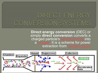
  • 1. Direct energy conversion (DEC) or simply direct conversion converts a charged particle's kinetic energy into a voltage. It is a scheme for power extraction from nuclear fusion
  • 2. Thermo electric power generation Thermo ionic power generation Magneto hydro dynamic systems Photovoltaic power systems Fuel cells Thermo nuclear fusion power generation
  • 3.
  • 4. The pioneer in thermoelectric was a German scientist Thomas Johann Seebeck (1770-1831) Thermoelectricity refers to a class of phenomena in which a temperature difference creates an electric potential or an electric potential creates a temperature difference. Thermoelectric power generator is a device that converts the heat energy into electrical energy based on the principles of Seebeck effect Later, In 1834, French scientist, Peltier and in 1851, Thomson (later Lord Kelvin) described the thermal effects on conductors
  • 5.  In the purer metallic conductors outer electrons, less connected to others, can move freely around all the material, as if they do not belong to any atom. These electrons transmit energy one to another through temperature variation, and this energy intensity varies depending on the nature of the material.  If two distinct materials are placed in contact, free electrons will be transferred from the more “loaded” material to the other, so they equate themselves, such transference creates a potential difference, called contact potential, since the result will be a pole negatively charged by the received electrons and another positively charged by the loss of electrons.
  • 6. When the junctions of two different metals are maintained at different temperature, the emf is produced in the circuit. This is known as Seebeck effect. The material A is maintained at T+∆T temperature The material B is maintained at temperature ‘T’. Since the junctions are maintained at different temperature, the emf ‘V’ flows across the circuit.
  • 7. • The electric potential produced by a temperature difference is known as the Seebeck effect and the proportionality constant is called the Seebeck coefficient. • If the free charges are positive (the material is p- type), positive charge will build up on the cold which will have a positive potential. • Similarly, negative free charges (n-type material) will produce a negative potential at the cold end.
  • 8. Whenever current passes through the circuit of two dissimilar conductors, depending on the current direction, either heat is absorbed or released at the junction of the two conductors. This is known as Peltier effect.
  • 9.
  • 10. Irreversible conversion of electrical energy into heat when a current I flows through a ressistance R.  Qj=I2R
  • 11.
  • 12.
  • 13.  Thermoelectric power generation (TEG) devices typically use special semiconductor materials, which are optimized for the Seebeck effect.  The simplest thermoelectric power generator consists of a thermocouple, comprising a p-type and n-type material connected electrically in series and thermally in parallel.  Heat is applied into one side of the couple and rejected from the opposite side.  An electrical current is produced, proportional to the temperature gradient between the hot and cold junctions.
  • 14.  Therefore, for any TEPG, there are four basic component required such as • Heat source (fuel) • P and N type semiconductor stack (TE module) • Heat sink (cold side) • Electrical load (output voltage)
  • 15.
  • 16.
  • 17. • As the heat moves from hot side to cold side, the charge carrier moves in the semiconductor materials and hence the potential deference is created. • The electrons are the charge carriers in the case of N- type semiconductor and Hole are in P-type semiconductors. • In a stack, number of P-type and N-type semiconductors is connected. • A single PN connection can produce a Seebeck voltage of 40 mV. • The heat source such as natural gas or propane are used for remote power generation
  • 18. Power P= I2RL V=IR I= V/R = P max = (when R=RL) = Figure of merit Z= L L s R RR T P 2 12                     R T P s 4 22 12           R s 2 12
  • 19.  Max. Ideal efficiency where: w is the power delivered to the external load and qH is the positive heat flow from source to sink                   hcm m h ch TTZT ZT T TT /1 11 max KR Z 2 21 )(    2 )( ch m TT T   RITKIT RI q w h l h 2 21 2 5.0)(     lRR T I    )( 21  R R m l  22/1 22 2/1 11 2 21 ])/()/[( )(   kk Z    Energy provided to the load Heat energy absorbed at the hot junctionEfficiency of the generator =   k kKR  l kA K )(  A l R )( 
  • 21.  A high electrical conductivity is necessary to minimize Joule heating and low thermal conductivity helps to retain heat at the junctions and maintain a large temperature gradient. A large Seebeck coefficient is advicable.These three properties were later put together and it is called figure-of-merit (Z).
  • 22. • The good thermoelectric materials should possess 1. Large Seebeck coefficients 2. High electrical conductivity 3. Low thermal conductivity  • The example for thermoelectric materials • BismuthTelluride (Bi2Te3), • Lead Telluride (PbTe), • SiliconGermanium (SiGe), • Bismuth-Antimony (Bi-Sb)
  • 23. • Easy maintenance: They works electrically without any moving parts so they are virtually maintenance free. • Environment friendly: Thermoelectric generators produce no pollution. Therefore they are eco friendly generators. • Compact and less weight: The overall thermoelectric cooling system is much smaller and lighter than a comparable mechanical system. • High Reliability: Thermoelectric modules exhibit very high reliability due to their solid-state construction • No noise: They can be used in any orientation and in zero gravity environments. Thus they are popular in many aerospace applications. • Convenient Power Supply: They operate directly from a DC power source.
  • 24.
  • 25. 31 Water/Beer Cooler Cooled Car Seat Electronic Cooling Cryogenic IR Night Vision Laser/OE Cooling TE Si bench
  • 26.  The standard material we work with is BiTe. The best efficiency that can be achieved with this material is approximately 6%.  But once the material is constructed into a module, efficiency drops to 3 to 4% because of thermal and electrical impedance. No other semiconductor material can perform as well as BiTe as far as efficiency is concerned. Other material such as PbTe are used but are far less efficient, and must be used at significantly higher temperatures (450°C- 600°C) hot side and are not commercially available!  Thermoelectric Seebeck effect modules are designed for very high power densities, on the order of 50 times greater than Solar PV!
  • 27.  Bismuth telluride is the best bulk TE material with ZT=1  Trends in TE devices: • Superlattices and nanowires: Increase in S, reduction in k • Nonequilibrium effects: decoupling of electron and phonon transport • Bulk nanomaterial synthesis  Trends in TE systems • Microrefrigeration based on thin film technologies • Automobile refrigeration • TE combined with fluidics for better heat exchangers  To match a refrigerator, an effective ZT= 4 is needed  To efficiently recover waste heat from car, ZT = 2 is needed
  • 28.
  • 29.
  • 30.  Thermionic emission is the basis for the working of this system.  In 1873, the Britain professor Frederic Guthrie invented the Thermionic phenomenon.  In 1883, Thomas A. Edison observed that the electrons are emitted from a metal surface when it was heated. This effect is called Edison effect.  Later in 1904, a British physicist John Ambrose Fleming developed two-element vacuum tube known as diode.
  • 31.  Thermionic power generator (TPG) is a static device that converts heat energy into electrical energy by boiling electrons from a hot emitter surface (= 1800K) across a small inter electrode gap (< 0.5 mm) to a cooler collector surface (= 1000K) 
  • 32. The idea of electrons leaving the surface
  • 33.
  • 34. • A thermionic energy converter (or) thermionic power generator is a device consisting of two electrodes placed near one another in a vacuum. • One electrode is normally called the cathode, or emitter, and the other is called the anode, or plate. • Ordinarily, electrons in the cathode are prevented from escaping from the surface by a potential-energy barrier. • When an electron starts to move away from the surface, it induces a corresponding positive charge in the material, which tends to pull it back into the surface. • To escape, the electron must somehow acquire enough energy to overcome this energy barrier. • At ordinary temperatures, almost none of the electrons can acquire enough energy to escape.
  • 35. • However, when the cathode is very hot, the electron energies are greatly increased by thermal motion. • At sufficiently high temperatures, a considerable number of electrons are able to escape. • The liberation of electrons from a hot surface is called thermionic emission
  • 36.
  • 37.
  • 38.  For the electrons to travel, the unit is at vacuum. This limit the size of the generator.  Electron emission is inhibited by space charge, small quantity of Cesium metal is introduced into the evacuated vessel  Molybdenum, tantalum, tungsten impregnated barium oxide.Uranium carbide, zirconium carbide.  Prototype combustion-heated thermionic systems for domestic heat and electric power cogeneration
  • 39.
  • 40.  Advantages • Higher efficiency and high power density • Compact to use  Disadvantages • There is a possibility of vaporization of emitter surface • Thermal breaking is possible during operation • The sealing is often gets failure
  • 41.
  • 42. An MHD generator is a device for converting heat energy of a fuel directly into electrical energy without conventional electric generator.  In advanced countries MHD generators are widely used but in developing countries like INDIA, it is still under construction, this construction work in in progress at TRICHI in TAMIL NADU, under the joint efforts of BARC (Bhabha atomic research center), Associated cement corporation (ACC) and Russian technologists.
  • 43. Magneto hydrodynamics (MHD) (magneto fluid dynamics or hydro magnetics) is the academic discipline which studies the dynamics of electrically conducting fluids. Examples of such fluids include plasmas, liquid metals, and salt water. The word magneto hydro dynamics (MHD) is derived from magneto- meaning magnetic field, and hydro- meaning liquid, and -dynamics meaning movement. The field of MHD was initiated by Hannes Alfvén , for which he received the Nobel Prize in Physics in 1970 Hannes Alfvén
  • 44.
  • 45.  This effect is a result of FARADAYS LAWS OF ELECTRO MAGNETIC INDUCTION. (i.e. when the conductor moves through a magnetic field, it generates an electric field perpendicular to the magnetic field & direction of conductor). The induced EMF is given by Eind = u x B where u = velocity of the conductor. B = magnetic field intensity. The induced current is given by, Iind = C x Eind where C = electric conductivity The retarding force on the conductor is the Lorentz force given by Find = Iind X B
  • 46.  The conducting fluid flow is forced between the plates with a kinetic energy and pressure differential sufficient to over come the magnetic induction force Find.  An ionized gas is employed as the conducting fluid.  Ionization is produced either by thermal means I.e. by an elevated temperature or by seeding with substance like cesium or potassium vapors which ionizes at relatively low temperatures.  The atoms of seed element split off electrons. The presence of the negatively charged electrons makes the gas an electrical conductor.
  • 47.
  • 48.
  • 49. 90% conductivity can be achieved with a fairly low degree of ionization of only about 1%.
  • 50.
  • 51.
  • 52.
  • 53. Open cycle MHD Closed cycle MHD Seeded Inert gas system. Liquid metal system  Temperature of CC MHD plants is very less compared to OC MHD plants. It’s about 1400oC.
  • 54.
  • 55.  The fuel used maybe oil through an oil tank or gasified coal through a coal gasification plant  The fuel (coal, oil or natural gas) is burnt in the combustor or combustion chamber.  The hot gases from combustor is then seeded with a small amount of ionized alkali metal (cesium or potassium) to increase the electrical conductivity of the gas.  The seed material, generally potassium carbonate is injected into the combustion chamber, the potassium is then ionized by the hot combustion gases at temperature of roughly 2300’ c to 2700’c.
  • 56.  To attain such high temperatures, the compressed air is used to burn the coal in the combustion chamber, must be adequate to at least 11000c.  A lower preheat temperature would be adequate if the air is enriched in oxygen. An alternative is used to compress oxygen alone for combustion of fuel, little or no preheating is then required. The additional cost of oxygen might be balanced by saving on the preheater.  The hot pressurized working fluid leaving the combustor flows through a convergent divergent nozzle. In passing through the nozzle, the random motion energy of the molecules in the hot gas is largely converted into directed, mass of energy. Thus , the gas emerges from the nozzle and enters the MHD generator unit at a high velocity.
  • 57.
  • 58.  In a closed cycle system the carrier gas operates in the form of Brayton cycle. In a closed cycle system the gas is compressed and heat is supplied by the source, at essentially constant pressure, the compressed gas then expands in the MHD generator, and its pressure and temperature fall. After leaving this generator heat is removed from the gas by a cooler, this is the heat rejection stage of the cycle. Finally the gas is recompressed and returned for reheating.  The complete system has three distinct but interlocking loops. On the left is the external heating loop. Coal is gasified and the gas is burnt in the combustor to provide heat. In the primary heat exchanger, this heat is transferred to a carrier gas argon or helium of the MHD cycle. The combustion products after passing through the air preheater and purifier are discharged to atmosphere.
  • 59.  Because the combustion system is separate from the working fluid, so also are the ash and flue gases. Hence the problem of extracting the seed material from fly ash does not arise. The flue gases are used to preheat the incoming combustion air and then treated for fly ash and sulfur dioxide removal, if necessary prior to discharge through a stack to the atmosphere.  The loop in the center is the MHD loop. The hot argon gas is seeded with cesium and resulting working fluid is passed through the MHD generator at high speed. The dc power out of MHD generator is converted in ac by the inverter and is then fed to the grid.
  • 60.
  • 61.  When a liquid metal provides the electrical conductivity, it is called a liquid metal MHD system.  An inert gas is a convenient carrier  The carrier gas is pressurized and heated by passage through a heat exchanger within combustion chamber. The hot gas is then incorporated into the liquid metal usually hot sodium to form the working fluid. The latter then consists of gas bubbles uniformly dispersed in an approximately equal volume of liquid sodium.  The working fluid is introduced into the MHD generator through a nozzle in the usual ways. The carrier gas then provides the required high direct velocity of the electrical conductor.
  • 62.  After passage through the generator, the liquid metal is separated from the carrier gas. Part of the heat exchanger to produce steam for operating a turbine generator. Finally the carrier gas is cooled, compressed and returned to the combustion chamber for reheating and mixing with the recovered liquid metal. The working fluid temperature is usually around 800’c as the boiling point of sodium even under moderate pressure is below 900’c.  At lower operating temp, the other MHD conversion systems may be advantageous from the material standpoint, but the maximum thermal efficiency is lower. A possible compromise might be to use liquid lithium, with a boiling point near 1300’c as the electrical conductor lithium is much more expensive than sodium, but losses in a closed system are less.
  • 63.
  • 64.  It has no moving parts & the actual conductors are replaced by ionized gas (plasma). The magnets used can be electromagnets or superconducting magnets.  The plasma temperature is typically over 2000 °C, the duct containing the plasma must be constructed from non- conducting materials capable of withstanding this high temperature. The electrodes must of course be conducting as well as heat resistant.  Superconducting magnets of 4~6Tesla are used. Here exhaust gases are again recycled & the capacities of these plants are more than 200MW.  Non-conducting walls of the channel must be constructed from an exceedingly heat-resistant substance such as yttrium oxide or zirconium dioxide to retard oxidation
  • 65.  Ionization of GAS:  Various methods for ionizing the gas are available, all of which depend on imparting sufficient energy to the gas. The ionization can be produced by thermal or nuclear means. Materials such as Potassium carbonate or Cesium are often added in small amounts, typically about 1% of the total mass flow to increase the ionization and improve the conductivity, particularly combustion of gas plasma
  • 66.  In MHD the thermal pollution of water is eliminated. (Clean Energy System)  Use of MHD plant operating in conjunction with a gas turbine power plant might not require to reject any heat to cooling water.  These are less complicated than the conventional generators, having simple technology.  There are no moving parts in generator which reduces the energy loss.  These plants have the potential to raise the conversion efficiency up to 55-60%. Since conductivity of plasma is very high (can be treated as infinity).  It is applicable with all kind of heat source like nuclear, thermal, thermonuclear plants etc. Extensive use of MHD can help in better fuel utilization.
  • 67.  The construction of superconducting magnets for small MHD plants of more than 1kW electrical capacity is only on the drawing board.  Difficulties may arise from the exposure of metal surface to the intense heat of the generator and form the corrosion of metals and electrodes.  Construction of generator is uneconomical due to its high cost.  Construction of Heat resistant and non conducting ducts of generator & large superconducting magnets is difficult.  MHD without superconducting magnets is less efficient when compared with combined gas cycle turbine.
  • 68. PhotovoltaicTheory p-Silicon n-Silicon + + + + + + + + + + + + + + + + + + - - - - - - - - - -
  • 69. PV System’s Components Solar Array Storage Batteries Charge Controller (Regulator) Inverter (For AC Systems Only)
  • 71. PV System’s Components Load Photovoltaic Array Battery Bank Inverter (AC loads) Charge Controller
  • 72. Design Strategy PV Array: Type Selection Sizing Climate & Geographical Location Considerations
  • 73. Design Strategy PV Array Types: Type Efficiency Cost Economical Feasibility Crystalline Silicon (c-Si) High 15-24% High Low Single Junction Low 5-10% Low Medium Amorphous Silicon (a-Si) Multi- Junction Medium 7.5-13% Low High
  • 74. Design Strategy PV Array Sizing: De-rating Factors  Aging 20%  Dirt Accumulation 20%  Future Growth 10% Recharging Period 4 days System Voltage Load Profile
  • 75. Design Strategy PV Array Climate & Geographical Location:  Solar Insolation (Radiation)  Effective Sun Hours  Array Orientation  Direction (Toward South)  Tilt Angle  Fixed Angle (Latitude + 10 Degrees)  Adjustable (Sun Tracking)
  • 78. Design Strategy Storage Battery: Type Selection Sizing Environment Considerations
  • 79. Design Strategy Storage Battery: Type Selection (cyclic application) Tubular Plate Lead-Acid Pocket Plate Nickel-Cadmium
  • 80. System Voltage Load Profile Backup Time (Autonomy) 7 days De-rating Factors Lead-Acid Ni-Cad Aging 25% 10% Temp. Compensation 19% 14% Design 10% 10% Design Strategy Storage Battery: Sizing
  • 81. No Temperature Control  Temp. Compensation Outdoor Battery Enclosure Shade Requirement Design Strategy Storage Battery: Environment Considerations
  • 82. Design Strategy Charge Regulator:  Type Selection  Single Stage  Multistage  Sizing (Array Rated Currents)  Temperature Compensation  Lead-Acid -5mV/oC/cell  Ni-Cad -3mV/oC/cell  Low Voltage Disconnect  Lead-Acid 1.85V/cell  Ni-Cad 1.15V/cell
  • 83. Applications Cathodic Protection Systems Telecommunications Systems SCADA Systems Offshore Platforms Highway Lighting Remote Homes Irrigation Water Pumping
  • 84. Advantages Reliable No Fuels Low Maintenance Long-term Savings No Pollution No Noise $ $ $
  • 85. Disadvantages High Initial Cost (3-10 times) Specialized Maintenance  Batteries  Power Conditioning Equipment Large Space $ $ $ $ $ $
  • 87. The Promise of Fuel Cells • “A score of nonutility companies are well advanced toward developing a powerful chemical fuel cell, which could sit in some hidden closet of every home silently ticking off electric power.” • Theodore Levitt, “Marketing Myopia,” Harvard Business Review, 1960 Theodore Levitt, “Marketing Myopia,” Harvard Business Review, 1960
  • 88. Parts of a Fuel Cell • Anode • Negative post of the fuel cell. • Conducts the electrons that are freed from the hydrogen molecules so that they can be used in an external circuit. • Etched channels disperse hydrogen gas over the surface of catalyst. • Cathode • Positive post of the fuel cell • Etched channels distribute oxygen to the surface of the catalyst. • Conducts electrons back from the external circuit to the catalyst • Recombine with the hydrogen ions and oxygen to form water. • Electrolyte • Proton exchange membrane. • Specially treated material, only conducts positively charged ions. • Membrane blocks electrons. • Catalyst • Special material that facilitates reaction of oxygen and hydrogen • Usually platinum powder very thinly coated onto carbon paper or cloth. • Rough & porous maximizes surface area exposed to hydrogen or oxygen • The platinum-coated side of the catalyst faces the PEM.
  • 89. Fuel Cell Operation • Pressurized hydrogen gas (H2) enters cell on anode side. • Gas is forced through catalyst by pressure. • When H2 molecule comes contacts platinum catalyst, it splits into two H+ ions and two electrons (e-). • Electrons are conducted through the anode • Make their way through the external circuit (doing useful work such as turning a motor) and return to the cathode side of the fuel cell. • On the cathode side, oxygen gas (O2) is forced through the catalyst • Forms two oxygen atoms, each with a strong negative charge. • Negative charge attracts the two H+ ions through the membrane, • Combine with an oxygen atom and two electrons from the external circuit to form a water molecule (H2O).
  • 90. PEM Fuel Cell Schematic
  • 93. Hydrogen Fuel Cell Efficiency • 40% efficiency converting methanol to hydrogen in reformer • 80% of hydrogen energy content converted to electrical energy • 80% efficiency for inverter/motor • Converts electrical to mechanical energy • Overall efficiency of 24-32%
  • 94. Auto Power Efficiency Comparison Technology System Efficiency Fuel Cell 24-32% Electric Battery 26% Gasoline Engine 20% http://www.howstuffworks.com/fuel-cell.htm/printable
  • 95. Fuel Cell Energy Exchange http://hyperphysics.phy-astr.gsu.edu/hbase/thermo/electrol.html
  • 96. Other Types of Fuel Cells • Alkaline fuel cell (AFC) • This is one of the oldest designs. It has been used in the U.S. space program since the 1960s. The AFC is very susceptible to contamination, so it requires pure hydrogen and oxygen. It is also very expensive, so this type of fuel cell is unlikely to be commercialized. • Phosphoric-acid fuel cell (PAFC) • The phosphoric-acid fuel cell has potential for use in small stationary power- generation systems. It operates at a higher temperature than PEM fuel cells, so it has a longer warm-up time. This makes it unsuitable for use in cars. • Solid oxide fuel cell (SOFC) • These fuel cells are best suited for large-scale stationary power generators that could provide electricity for factories or towns. This type of fuel cell operates at very high temperatures (around 1,832 F, 1,000 C). This high temperature makes reliability a problem, but it also has an advantage: The steam produced by the fuel cell can be channeled into turbines to generate more electricity. This improves the overall efficiency of the system. • Molten carbonate fuel cell (MCFC) • These fuel cells are also best suited for large stationary power generators. They operate at 1,112 F (600 C), so they also generate steam that can be used to generate more power. They have a lower operating temperature than the SOFC, which means they don't need such exotic materials. This makes the design a little less expensive. http://www.howstuffworks.com/fuel-cell.htm/printable
  • 97. Advantages/Disadvantages of Fuel Cells • Advantages • Water is the only discharge (pure H2) • Disadvantages • CO2 discharged with methanol reform • Little more efficient than alternatives • Technology currently expensive • Many design issues still in progress • Hydrogen often created using “dirty” energy (e.g., coal) • Pure hydrogen is difficult to handle • Refilling stations, storage tanks, …
  • 98.
  • 99.
  • 100.
  • 101.  There are great challenges that are associated with fusion, but there are also very large possible benefits  A coal power plant uses 9000 tons of coal a day to produce 1000 MW and emits many pollutants including 30,000 tons of carbon dioxide  A fusion power plant would use 5.35Kg of deuterium and tritium for the same amount of power and would emit only 4.28Kg of helium  The amount of lithium contained in a single computer battery along with about half of a bathtub full of water can produce as much energy as 40 tons of coal
  • 102.
  • 103.
  • 104.  Deuterium ------------  In ocean water---- 1 D atom for every 6500 ordinary H atom in sea water.  Tritium is produced in nuclear reactors by neutron activation of lithium-6.  Tritium is also produced in heavy water-moderated reactors whenever a deuterium nucleus captures a neutron.  Tritium is an uncommon product of the nuclear fission of uranium-235, plutonium-239, and uranium-233, with a production of about one per each 10,000 fissions
  • 105. The electrostatic force between the positively charged nuclei is repulsive, but when the separation is small enough, the attractive nuclear force is stronger. Therefore the prerequisite for fusion is that the nuclei have enough kinetic energy that they can approach each other despite the electrostatic repulsion.
  • 106.  Lawson criterion, first derived on fusion reactors (initially classified) by John D. Lawson in 1955 and published in 1957.  Is an important general measure of a system that defines the conditions needed for a fusion reactor to reach ignition, that is, the heating of the plasma by the products of the fusion reactions is sufficient to maintain the temperature of the plasma against all losses without external power input.  Breakeven is the point in which the energy supplied equals or exceeds the energy output  Ignition is the point in which the energy from fusion supplies the heat necessary to sustain the reaction without external sources
  • 107.  As originally formulated the Lawson criterion gives a minimum required value for the product of the plasma (electron) density ne and the "energy confinement time" .  Later analysis suggested that a more useful figure of merit is the "triple product" of density, confinement time, and plasma temperature T. The triple product also has a minimum required value, and the name "Lawson criterion" often refers to this inequality
  • 108. Minimum value of (electron density * energy confinement time) required for self-heating, for three fusion reactions. For DT, neτE minimizes near the temperature 25 keV (300 million kelvins). The fusion triple product condition for three fusion reactions.
  • 109.  In terms of reaction rate. (m3/s), break even condition.  For a D-T plasma at 100million oC the break even condition is around 6 X10¹³ sec/cm3
  • 110. Why?  Even if you manage to generate extremely high temperatures needed to initiate nuclear fusion reactions, there is no material container which can withstand such temperatures.  One solution to this dilemma is to keep the hot plasma out of contact with the walls of its container by keeping it moving in circular or helical paths by means of the magnetic force on charged particles. 1. Magnetic confinement.(1015 particle density, time 0.1sec) 2. Inertial confinement.(1026 nuclei/cm3, 10-12 sec)
  • 111.  The motion of electrically charged particles is constrained by a magnetic field.  In the absence of the magnetic field heated particles will move in straight lines in random directions, quickly striking the walls of the container. When a uniform magnetic field is applied the charged particles will follow spiral paths encircling the magnetic lines of force. The motion of the particles across the magnetic field lines is restricted and so is the access to the walls of the container.
  • 112. Magnetic fields… • Toroidal field • Poloidal field
  • 113. 1. Laser beams or laser-produced X-rays rapidly heat the surface of the fusion target, forming a surrounding plasma envelope.(ablation) 2. Fuel is compressed by the rocket-like blowoff of the hot surface material.(implosion) 3. During the final part of the capsule implosion, the fuel core reaches 20 times the density of lead and ignites at 100,000,000 ˚C. 4. Thermonuclear burn spreads rapidly through the compressed fuel, yielding many times the input energy.
  • 114.
  • 115.
  • 116.  In the inertial confinement fusion method a very large plasma density (more than twenty times the density of lead) is attained at the expense of the energy confinement time.  In the magnetic confinement method an energy confinement time longer than one second is attained in very low density plasmas.  A density of solid D-T (0.2 g/cm³) would require an implausibly large laser pulse energy. Assuming the energy required scales with the mass of the fusion plasma (Elaser ~ ρR3 ~ ρ−2), compressing the fuel to 103 or 104 times solid density would reduce the energy required by a factor of 106 or 108, bringing it into a realistic range.
  • 117.  With a compression by 103, the compressed density will be 200 g/cm³, and the compressed radius can be as small as 0.05 mm. The radius of the fuel before compression would be 0.5 mm. The initial pellet will be perhaps twice as large since most of the mass will be ablated during the compression.  The optimum temperature for inertial confinement fusion is that which maximizes <σv>/T 3/2, which is slightly higher than the optimum temperature for magnetic confinement.
  • 118.
  • 119.
  • 120. Magnetic confinement fusion….. Tokamak reactor. Inertial confinement fusion
  • 121.
  • 123.
  • 124.
  • 125.
  • 126. Presented By Anil Kumar(1244408) Rahul Kumar(1244430) Chandan Kumar Chanchal(1244415) Rajkumar Prasad Yadav(1244435) Arjun Kumar(1244409) Anil Kumar(1244407) Ashraful Alom(1244410)