SlideShare uma empresa Scribd logo
1 de 12
Baixar para ler offline
ARDUINO SEVERINO
                SERIAL SINGLE SIDED VERSION 3
                       S3v3 (REVISION 2)
                        USER MANUAL


X1:
DE-9 serial connector

Used to connect computer (or other devices) using RS -232 standard.
Needs a serial cable, with at least 4 pins connected: 2, 3, 4 and 5.
Works only when JP0 is set to 2-3 position.


DC1:
2.1 mm. power jack

Used to connect external power source. Centre positive.
Voltage Regulator Works with regulated +7 to +20 volts DC (9v. to
12v. is recommended).
It is possible to alternatively connect external power using 9v. pin or
5v. pin. (see POWER PINOUT)
ICSP:
2x3 pin header

Used to program Atmega with bootloader. The number 1 on both sides
of the board indicates cable pin1 position.

Used to upload sketches on Atmega ICs without bootloader (available
only in Arduino IDE versions 0011 and 0012).


JP0
3 pins jumper

When in position 2-3, this jumper enables serial connection (through
X1 connector) to/from computer/devices. Use this as default position.

When in position 1 -2, it disables serial communication, and enables
external pull -down resistors on pin0 (RX) and pin1 (TX). Use this only
to prevent noise on RX (that seems incoming data to Atmega), that
sometimes makes sketch not starting.

When removing this jumper, serial communication           is disabled, and
pin0 and pin1 work as a normal (flo ating) digital       pin. Useful when
more digital pins are needed, but only when serial       communication is
not necessary. External pull-down/pull -up resistor is   required.


JP4
2 pins jumper

When in position 1 -2, this jumper enables auto reset feature, useful
when uploading a sketch to Arduino, resetting Atmega automatically.
It makes unnecessary to press reset button (S1) when uploading
sketches.
Be sure that computer COM Port speed is set to 19200bps otherwise
auto reset will not work properly.

If removed, disables auto reset feature. Very useful to prevent
undesired Atmega reset when using sketches that needs serial
communication.
Auto reset works with DTR pulse on serial pin4. Sometimes Arduino
senses a DTR pulse when connecting X1 (serial connector) and some
softwares sends a DTR pulse when it starts or when it closes , that
makes Atmega reset when not desired.
S1
Tactile button

This button resets Atmega, to restart uploaded sketch or to prepare
Arduino to receive a sketch through serial connector (when auto reset
is not active).


LEDS
Indicative leds

POWER led
Turns on when Arduino is powered through DC1, +9v. pin or +5v. pin.

RX led
Blinks when receiving data from computer/device through serial
connection.

TX led
Blinks when       sending   data   to   computer/device   through   serial
connection.

L led
This led is connected to digital pin13 with a current limiter resistor
(that doesn’t affect pin13). Useful to test sketches. It is normal to
blink when bootloading too.


POWER PINOUT
6 pin header

RST pin
Makes Atmega reset when connected to GND. Useful for Shield
Boards, or to connect external reset.

NC pin
This pin is not connected in Arduino S3v3. Arduino Diecimila has a
3.3 volts pin in the same position.
+9v. pin
When Arduino DC1 is powered (with battery or DC adaptor), this pin is
used as Vout, with the same voltage supplied on DC1 (see DC1),
minus 0,7 volts. The total supplied current depends on external power
source capacity

When Arduino DC1 is not powered, +9v. pin can be used as Vin,
connecting it to a external regulated power source (+ 7 to +20 volts)
and connecting 0v . pin to external power source GND. In this case,
+5v. pin can be used as Vout, supplying +5 volts.

+5v. pin
When Arduino DC1 is powered (with battery or DC adaptor), + 5 v . pin
supplies +5 volts as a Vout pin. The total s upplied current depends on
Voltage Regulator (7805 supplies up to 1A). This applies only to +5v.
pin: Atmega in/out pins only supplies max. 40mA on each pin.
When Arduino DC1 is not powered, this pin can be used as Vin,
connecting it to a regulated +5v. and connecting 0v . pin to power
source GND. In this case, +9v . pin is inactive.


0v. pin (GND)
Two 0v. pins between +5v. and +9v. / One 0v. pin beside AREF pin.
When Arduino DC1 is powered, 0v. pin supplies 0 volts reference
(GND) for +5v. pin and +9v. pin.
When DC1 is not powered, and Arduino is powered through +5v. pin
or +9v. pin, 0v. pin must be used as GND reference, c onnecting it to
the external power source GND.


DIGITAL IN/OUT PINOUT
8 pin header (x2)

8 digital inputs/outputs: 0 to 7, corresponding to Port D.
Pin0 (RX) and pin1 (TX) can be used as communication pins.
Pin3, pin5 and pin6 can be used as PWM pins (Atmega168 only).

6 digital inputs/outputs: 8 to 13, corresponding to Port B.
Pin10 (SS), pin11 (MOSI), pin12 (MISO) and pin13 (SCK) can be used
as SPI (Serial Peripheral Interface).
Pin9, pin10 and pin11 can be used as PWM pins (Atmega8 and
Atmega168).
ANALOG IN PINOUT
6 pin header

6 analog inputs: 0 to 5, corresponding to Port C.
Pin4 (SDA) and pin5 (SCL) can be used with I2C (two-w ire serial
bus).

The analog input pins can be used as digital pins with numbers 14
(analog input 0) to 19 (analog input 5).


1 GND pin
see 0v. pin (GND).


AREF pin
The AREF can be set to AVcc (default), internal 2.56 volts (Atmega8),
internal 1.1 volts (Atmega168), or external AREF.
In case of AVcc or internal AREF, AREF pin can be used to attach na
external capacitor to decouple the signal, for better noise
performance.

In case of external AREF, AREF pin is used to attach the external
reference voltage.
Remember that it is necessary to change de fuses (wiring.c file), and
re -upload sketch, before connecting external voltage to AREF.


SOFTWARE TIPS

When bootloading na Atmega8 chip with Arduino 0010, there is a
command (-i800) that makes bootloader delay 10 minutes. So, if you
need to use bootloader, use command line instead of IDE, removing
“– i800” command and adding “–F ” command, or use Arduino 0007
IDE. To upload sketches Ard uino 0010 works fine.
ARDUINO S3v3 NEW FEATURES


 •   full compatible with Shield Boards (Version 2 is the only Arduino
     Board not compatible with Shield Boards because of ICSP
     header wrong position, and tall components);

 •   AVcc LP filter to reduce noise level on ADC;

 •   auto reset feature ;

 •   auto reset enable/disable jumper, to avoid not desired reseting;

 •   arduino Diecimila compatible reset pin ;

 •   pin13 onboard led, with current limiter resistor;

 •   TX and RX onboard leds ;

 •   power led with appropriate current limiter resistor (less 20mA of
     comsumption);

 •   jumper to disable serial communication and to enable RX
     external pull down resistor, to avoid “RX floating error”. This
     feature allows to use digital pin0 and pin1 as a normal pin, when
     serial communication is not need ed;

 •   all similar components (diodes, transistors, leds, capacitors)
     has the same board orientation (to makes easier to mount with
     less mistakes);

 •   no wires between pads, more space between wires, larger
     wires, larger pads (better for etching, soldering and drilling, with
     no short circuits, soldering bridges or open wires in corrosion);

 •   only 3 wire bridges;

 •   electrolitic capacitor (in serial to TTL circuit) changed to bipolar
     type (to avoid inverted voltage problem when serial cable is not
     connected);

 •   All jumpers are right angle type, to allow Shield Boards use.


       www.arduino.cc                           Adilson Akashi – 2 7 /d e c /2 0 0 8
ARDUINO SEVERINO
SERIAL SINGLE SIDED VERSION 3
       S3v3 (REVISION 2)
      MOUNTING MANUAL
BILL OF MATERIAL FOR ARDUINO SERIAL SINGLE SIDED VERSION 3 (S3V3) - REVISION 2
QTY POSITION DESCRIPTION                        VALUE                                DETAIL
    2 C1, C2     ceramic disc capacitor         22pF (22 pico Farad)
    4 C3, C4,    ceramic or polyester capacitor 100nF (100 nano Farad - or 0.1 micro
      C6, C7                                    Farad)
    2 C5, C8     electrolytic capacitor         100µF (100 micro Farad)              16volts (or more: 25v)      radial-lead
    1 C9         non-polarized electrolytic     10µF (10 micro Farad)                16volts (or more: 25v, 50v) radial-lead
                 capacitor
    1 D1         diode                          1N4004                               DO41-10
    2 D2, D3     diode                          1N4148                               DO35-10
    1 DC1        2.1mm. DC power jack
    1 IC1        ATMEGA8 (or ATMEGA168)                                              28P3 package
    1 IC2        Tension Regulator              7805C
    1 ICSP       male pin header                2x3
    2 J1, J3     female pin header              1x8                                  0.1" (or 2.54 mm.)
    2 J2,        female pin header              1x6                                  0.1" (or 2.54 mm.)
      POWER
    1 JP0        right angle pin header         1x3                                  0.1" (or 2.54 mm.)
    1 JP4        right angle pin header         1x2                                  0.1" (or 2.54 mm.)
    1 L1         leaded inductor                100µH (100 micro Henry)              axial leaded                (silver)brown, black,
                                                                                                                 brown, golden
    4 LED0,      LED                            3 mm.                                choose colors
      LED1,
      LED13,
      LED14
    1 Q1         16 MHz crystal
    5 R1, R2,    Resistor                       1kohm (1.0 kilo ohms)                1/4 Watt, ±5%               brown, black, red, gold
      R3, R4, R6

    1 R9         Resistor                      4k7ohms (4.7 kilo ohms)                1/4 Watt, ±5%               yellow, violet, red, gold
    5 R5, R7,    Resistor                      10kohms (10.0 kilo ohms)               1/4 Watt, ±5%               brown, black, orange,
      R8, R10,                                                                                                    gold
      R11
    1 S1         Switch Tactile                6x6 mm., 4 terminals                                               B3F-10XX
    1 T1         Transistor                    BC547                                  NPN general purpose         TO92
                                                                                      transistor
    1 T2         Transistor                    BC557                                  PNP general purpose         TO92
                                                                                      transistor
    1 X1         D-SUB CONNECTOR               9 PIN FEMALE RIGHT ANGLE PC            DE-9 CONNECTOR
                                               MOUNT
    2 Jumpers    jumper for 0.1" header                                               0.1" (or 2.54 mm.)
PART LIST FOR ARDUINO SERIAL SINGLE SIDED VERSION 3 (S3V3) - REVISION 2
POSITION VALUE                                         DESCRIPTION                            DETAIL
C1         22pF (22 pico Farad)                        ceramic disc capacitor
C2         22pF (22 pico Farad)                        ceramic disc capacitor
C3         100nF (100 nano Farad - or 0.1 micro Farad) ceramic or polyester capacitor
C4         100nF (100 nano Farad - or 0.1 micro Farad) ceramic or polyester capacitor
C5         100µF (100 micro Farad)                     electrolytic capacitor                 16volts (or more: 25v)         radial-lead
C6         100nF (100 nano Farad - or 0.1 micro Farad) ceramic or polyester capacitor
C7         100nF (100 nano Farad - or 0.1 micro Farad) ceramic or polyester capacitor                                        radial-lead
C8         100µF (100 micro Farad)                     electrolytic capacitor                 16volts (or more: 25v)         radial-lead
C9         10µF (10 micro Farad)                       non-polarized electrolytic capacitor   16volts (or more: 25v, 50v)    radial-lead
D1         1N4004                                      diode                                  DO41-10
D2         1N4148                                      diode                                  DO35-10
D3         1N4148                                      diode                                  DO35-10
DC1                                                    2.1mm. DC power jack
IC1                                                    ATMEGA8 (or ATMEGA168)                 28P3 package
IC2        7805C                                       Tension Regulator
ICSP       2x3                                         male pin header                                                       ICSP
J1         1x8                                         female pin header                      0.1" (or 2.54 mm.)             PORT D(D0-D7)
J2         1x6                                         female pin header                      0.1" (or 2.54 mm.)             PORT C(A0-A5)
J3         1x8                                         female pin header                      0.1" (or 2.54 mm.)             PORT B(D8-D13)
JP0        1x3                                         right angle pin header                 0.1" (or 2.54 mm.)
JP4        1x2                                         right angle pin header                 0.1" (or 2.54 mm.)             AUTO RESET
L1         100µH                                       leaded inductor                        axial leaded                   (silver)brown, black, brown, golden
LED0       3 mm.                                       LED                                    choose a color                 Rx Led
LED1       3 mm.                                       LED                                    choose a color                 Tx Led
LED13      3 mm.                                       LED                                    choose a color                 Pin13 Led
LED14      3 mm.                                       LED                                    choose a color                 Power Led
POWER      1x6                                         female pin header
Q1                                                     16 MHz crystal
R1         1kohm (1.0 kilo ohm)                        Resistor                               1/4 Watt, ±5%                  brown, black, red, gold
R2         1kohm (1.0 kilo ohm)                        Resistor                               1/4 Watt, ±5%                  brown, black, red, gold
R3         1kohm (1.0 kilo ohm)                        Resistor                               1/4 Watt, ±5%                  brown, black, red, gold
R4         1kohm (1.0 kilo ohm)                        Resistor                               1/4 Watt, ±5%                  brown, black, red, gold
R5         10kohms (10.0 kilo ohms)                    Resistor                               1/4 Watt, ±5%                  brown, black, orange, gold
R6         1kohm (1.0 kilo ohm)                        Resistor                               1/4 Watt, ±5%                  brown, black, red, gold
R7         10kohms (10.0 kilo ohms)                    Resistor                               1/4 Watt, ±5%                  brown, black, orange, gold
R8         10kohms (10.0 kilo ohms)                    Resistor                               1/4 Watt, ±5%                  brown, black, orange, gold
R9         4k7ohms (4.7 kilo ohms)                     Resistor                               1/4 Watt, ±5%                  yellow, violet, red, gold
R10        10kohms (10.0 kilo ohms)                    Resistor                               1/4 Watt, ±5%                  brown, black, orange, gold
R11        10kohms (10.0 kilo ohms)                    Resistor                               1/4 Watt, ±5%                  brown, black, orange, gold
S1         6x6 mm., 4 terminals                        Switch Tactile                                                        B3F-10XX
T1         BC547                                       Transistor                             NPN general purpose transistor TO92
T2         BC557                                       Transistor                             PNP general purpose transistor TO92
X1         9 PIN FEMALE RIGHT ANGLE PC MOUNT D-SUB CONNECTOR                                  DE-9 CONNECTOR
jumper                                                 0.1" (or 2.54 mm.)
PCB – SOLDERING SIDE (Mirror Image)


PCB – COMPONENT SIDE (Mirror Image)
SCHEMATIC


DRILLING DIAGRAM (Soldering Side View)
MOUNTING DIAGRAM (Component Side View)


Mounting Tips

Pay attention to LED’s lateral chamfer, electrolitical capacitor’s
negative (-) pole mark (mounting diagram has positive (+) mark),
diode’s stripe, Atmega IC’s and IC socket ’s notch, and transistor’s
numbers and positions. Note that similar components have the same
board orientation.

Mais conteúdo relacionado

Mais procurados

Mais procurados (19)

WEBINAR - VIPer Plus
WEBINAR - VIPer PlusWEBINAR - VIPer Plus
WEBINAR - VIPer Plus
 
Tk2050
Tk2050Tk2050
Tk2050
 
MUSES8920の英語のデータシート
MUSES8920の英語のデータシートMUSES8920の英語のデータシート
MUSES8920の英語のデータシート
 
Afc ppt
Afc pptAfc ppt
Afc ppt
 
Tripath TA2021B
Tripath TA2021BTripath TA2021B
Tripath TA2021B
 
Edwards Signaling E-NAC Data Sheet
Edwards Signaling E-NAC Data SheetEdwards Signaling E-NAC Data Sheet
Edwards Signaling E-NAC Data Sheet
 
Arduino projects & tutorials
Arduino projects & tutorialsArduino projects & tutorials
Arduino projects & tutorials
 
Vip Er22a
Vip Er22aVip Er22a
Vip Er22a
 
ELECTRICAL PROJECT ABSTRACT-Embedded pic microcontroller based motor protecti...
ELECTRICAL PROJECT ABSTRACT-Embedded pic microcontroller based motor protecti...ELECTRICAL PROJECT ABSTRACT-Embedded pic microcontroller based motor protecti...
ELECTRICAL PROJECT ABSTRACT-Embedded pic microcontroller based motor protecti...
 
Ru series (1)
Ru series (1)Ru series (1)
Ru series (1)
 
74 Lcx08
74 Lcx0874 Lcx08
74 Lcx08
 
DAC0800 8-Bit DAC Datasheet
DAC0800 8-Bit DAC DatasheetDAC0800 8-Bit DAC Datasheet
DAC0800 8-Bit DAC Datasheet
 
8000 series datasheet
8000 series datasheet8000 series datasheet
8000 series datasheet
 
Tle4904 343973
Tle4904 343973Tle4904 343973
Tle4904 343973
 
4057
40574057
4057
 
Td1410
Td1410Td1410
Td1410
 
Power Management IC Overview
Power Management IC OverviewPower Management IC Overview
Power Management IC Overview
 
P700; 75-150A Programmable Power Controller
P700; 75-150A Programmable Power ControllerP700; 75-150A Programmable Power Controller
P700; 75-150A Programmable Power Controller
 
Photoelectric detectors xs
Photoelectric detectors xsPhotoelectric detectors xs
Photoelectric detectors xs
 

Semelhante a Arduino severinomanual2

Arduino severinomanual2
Arduino severinomanual2Arduino severinomanual2
Arduino severinomanual2Muhammad Khan
 
Open Hardware: Arduino #barcampmexico
Open Hardware: Arduino #barcampmexicoOpen Hardware: Arduino #barcampmexico
Open Hardware: Arduino #barcampmexicoGonzalo Maldonado
 
MAN0852_HE-XE102-10_8-21-07
MAN0852_HE-XE102-10_8-21-07MAN0852_HE-XE102-10_8-21-07
MAN0852_HE-XE102-10_8-21-07Dana Kincaid
 
40 Watt Bass Amplifier Circuit
40 Watt Bass Amplifier Circuit40 Watt Bass Amplifier Circuit
40 Watt Bass Amplifier Circuitlukewillsonwill
 
Advanced motion controls azbe12a8
Advanced motion controls azbe12a8Advanced motion controls azbe12a8
Advanced motion controls azbe12a8Electromate
 
Arduino windows remote control
Arduino windows remote controlArduino windows remote control
Arduino windows remote controlVilayatAli5
 
Advanced motion controls azbe6a8
Advanced motion controls azbe6a8Advanced motion controls azbe6a8
Advanced motion controls azbe6a8Electromate
 
1396740 634706422070340000
1396740 6347064220703400001396740 634706422070340000
1396740 634706422070340000bnsprasad
 
International Journal of Engineering Research and Development
International Journal of Engineering Research and DevelopmentInternational Journal of Engineering Research and Development
International Journal of Engineering Research and DevelopmentIJERD Editor
 
Netzer DS-247-128 Specsheet
Netzer DS-247-128 Specsheet Netzer DS-247-128 Specsheet
Netzer DS-247-128 Specsheet Electromate
 
Advanced motion controls azbdc10a4
Advanced motion controls azbdc10a4Advanced motion controls azbdc10a4
Advanced motion controls azbdc10a4Electromate
 
Basic electronic components used in robotics
Basic electronic components used in roboticsBasic electronic components used in robotics
Basic electronic components used in roboticsKshitij Wagle
 

Semelhante a Arduino severinomanual2 (20)

Arduino severinomanual2
Arduino severinomanual2Arduino severinomanual2
Arduino severinomanual2
 
Open Hardware: Arduino #barcampmexico
Open Hardware: Arduino #barcampmexicoOpen Hardware: Arduino #barcampmexico
Open Hardware: Arduino #barcampmexico
 
MAN0852_HE-XE102-10_8-21-07
MAN0852_HE-XE102-10_8-21-07MAN0852_HE-XE102-10_8-21-07
MAN0852_HE-XE102-10_8-21-07
 
Smart Blind stick by using arduino uno and sensor
 Smart Blind stick  by using arduino  uno  and sensor Smart Blind stick  by using arduino  uno  and sensor
Smart Blind stick by using arduino uno and sensor
 
40 Watt Bass Amplifier Circuit
40 Watt Bass Amplifier Circuit40 Watt Bass Amplifier Circuit
40 Watt Bass Amplifier Circuit
 
Advanced motion controls azbe12a8
Advanced motion controls azbe12a8Advanced motion controls azbe12a8
Advanced motion controls azbe12a8
 
Arduino windows remote control
Arduino windows remote controlArduino windows remote control
Arduino windows remote control
 
Arduino Projects.pptx
Arduino Projects.pptxArduino Projects.pptx
Arduino Projects.pptx
 
Advanced motion controls azbe6a8
Advanced motion controls azbe6a8Advanced motion controls azbe6a8
Advanced motion controls azbe6a8
 
1396740 634706422070340000
1396740 6347064220703400001396740 634706422070340000
1396740 634706422070340000
 
International Journal of Engineering Research and Development
International Journal of Engineering Research and DevelopmentInternational Journal of Engineering Research and Development
International Journal of Engineering Research and Development
 
Power amplifier (2) tugas
Power amplifier (2)  tugasPower amplifier (2)  tugas
Power amplifier (2) tugas
 
Neno Project.docx
Neno Project.docxNeno Project.docx
Neno Project.docx
 
Speed control of motor
Speed control of motorSpeed control of motor
Speed control of motor
 
3030
30303030
3030
 
Tm 7000 analog
Tm 7000 analogTm 7000 analog
Tm 7000 analog
 
Netzer DS-247-128 Specsheet
Netzer DS-247-128 Specsheet Netzer DS-247-128 Specsheet
Netzer DS-247-128 Specsheet
 
Advanced motion controls azbdc10a4
Advanced motion controls azbdc10a4Advanced motion controls azbdc10a4
Advanced motion controls azbdc10a4
 
Basic electronic components used in robotics
Basic electronic components used in roboticsBasic electronic components used in robotics
Basic electronic components used in robotics
 
Ge8808 led datasheet
Ge8808 led datasheetGe8808 led datasheet
Ge8808 led datasheet
 

Arduino severinomanual2

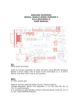
  • 1. ARDUINO SEVERINO SERIAL SINGLE SIDED VERSION 3 S3v3 (REVISION 2) USER MANUAL X1: DE-9 serial connector Used to connect computer (or other devices) using RS -232 standard. Needs a serial cable, with at least 4 pins connected: 2, 3, 4 and 5. Works only when JP0 is set to 2-3 position. DC1: 2.1 mm. power jack Used to connect external power source. Centre positive. Voltage Regulator Works with regulated +7 to +20 volts DC (9v. to 12v. is recommended). It is possible to alternatively connect external power using 9v. pin or 5v. pin. (see POWER PINOUT)
  • 2. ICSP: 2x3 pin header Used to program Atmega with bootloader. The number 1 on both sides of the board indicates cable pin1 position. Used to upload sketches on Atmega ICs without bootloader (available only in Arduino IDE versions 0011 and 0012). JP0 3 pins jumper When in position 2-3, this jumper enables serial connection (through X1 connector) to/from computer/devices. Use this as default position. When in position 1 -2, it disables serial communication, and enables external pull -down resistors on pin0 (RX) and pin1 (TX). Use this only to prevent noise on RX (that seems incoming data to Atmega), that sometimes makes sketch not starting. When removing this jumper, serial communication is disabled, and pin0 and pin1 work as a normal (flo ating) digital pin. Useful when more digital pins are needed, but only when serial communication is not necessary. External pull-down/pull -up resistor is required. JP4 2 pins jumper When in position 1 -2, this jumper enables auto reset feature, useful when uploading a sketch to Arduino, resetting Atmega automatically. It makes unnecessary to press reset button (S1) when uploading sketches. Be sure that computer COM Port speed is set to 19200bps otherwise auto reset will not work properly. If removed, disables auto reset feature. Very useful to prevent undesired Atmega reset when using sketches that needs serial communication. Auto reset works with DTR pulse on serial pin4. Sometimes Arduino senses a DTR pulse when connecting X1 (serial connector) and some softwares sends a DTR pulse when it starts or when it closes , that makes Atmega reset when not desired.
  • 3. S1 Tactile button This button resets Atmega, to restart uploaded sketch or to prepare Arduino to receive a sketch through serial connector (when auto reset is not active). LEDS Indicative leds POWER led Turns on when Arduino is powered through DC1, +9v. pin or +5v. pin. RX led Blinks when receiving data from computer/device through serial connection. TX led Blinks when sending data to computer/device through serial connection. L led This led is connected to digital pin13 with a current limiter resistor (that doesn’t affect pin13). Useful to test sketches. It is normal to blink when bootloading too. POWER PINOUT 6 pin header RST pin Makes Atmega reset when connected to GND. Useful for Shield Boards, or to connect external reset. NC pin This pin is not connected in Arduino S3v3. Arduino Diecimila has a 3.3 volts pin in the same position.
  • 4. +9v. pin When Arduino DC1 is powered (with battery or DC adaptor), this pin is used as Vout, with the same voltage supplied on DC1 (see DC1), minus 0,7 volts. The total supplied current depends on external power source capacity When Arduino DC1 is not powered, +9v. pin can be used as Vin, connecting it to a external regulated power source (+ 7 to +20 volts) and connecting 0v . pin to external power source GND. In this case, +5v. pin can be used as Vout, supplying +5 volts. +5v. pin When Arduino DC1 is powered (with battery or DC adaptor), + 5 v . pin supplies +5 volts as a Vout pin. The total s upplied current depends on Voltage Regulator (7805 supplies up to 1A). This applies only to +5v. pin: Atmega in/out pins only supplies max. 40mA on each pin. When Arduino DC1 is not powered, this pin can be used as Vin, connecting it to a regulated +5v. and connecting 0v . pin to power source GND. In this case, +9v . pin is inactive. 0v. pin (GND) Two 0v. pins between +5v. and +9v. / One 0v. pin beside AREF pin. When Arduino DC1 is powered, 0v. pin supplies 0 volts reference (GND) for +5v. pin and +9v. pin. When DC1 is not powered, and Arduino is powered through +5v. pin or +9v. pin, 0v. pin must be used as GND reference, c onnecting it to the external power source GND. DIGITAL IN/OUT PINOUT 8 pin header (x2) 8 digital inputs/outputs: 0 to 7, corresponding to Port D. Pin0 (RX) and pin1 (TX) can be used as communication pins. Pin3, pin5 and pin6 can be used as PWM pins (Atmega168 only). 6 digital inputs/outputs: 8 to 13, corresponding to Port B. Pin10 (SS), pin11 (MOSI), pin12 (MISO) and pin13 (SCK) can be used as SPI (Serial Peripheral Interface). Pin9, pin10 and pin11 can be used as PWM pins (Atmega8 and Atmega168).
  • 5. ANALOG IN PINOUT 6 pin header 6 analog inputs: 0 to 5, corresponding to Port C. Pin4 (SDA) and pin5 (SCL) can be used with I2C (two-w ire serial bus). The analog input pins can be used as digital pins with numbers 14 (analog input 0) to 19 (analog input 5). 1 GND pin see 0v. pin (GND). AREF pin The AREF can be set to AVcc (default), internal 2.56 volts (Atmega8), internal 1.1 volts (Atmega168), or external AREF. In case of AVcc or internal AREF, AREF pin can be used to attach na external capacitor to decouple the signal, for better noise performance. In case of external AREF, AREF pin is used to attach the external reference voltage. Remember that it is necessary to change de fuses (wiring.c file), and re -upload sketch, before connecting external voltage to AREF. SOFTWARE TIPS When bootloading na Atmega8 chip with Arduino 0010, there is a command (-i800) that makes bootloader delay 10 minutes. So, if you need to use bootloader, use command line instead of IDE, removing “– i800” command and adding “–F ” command, or use Arduino 0007 IDE. To upload sketches Ard uino 0010 works fine.
  • 6. ARDUINO S3v3 NEW FEATURES • full compatible with Shield Boards (Version 2 is the only Arduino Board not compatible with Shield Boards because of ICSP header wrong position, and tall components); • AVcc LP filter to reduce noise level on ADC; • auto reset feature ; • auto reset enable/disable jumper, to avoid not desired reseting; • arduino Diecimila compatible reset pin ; • pin13 onboard led, with current limiter resistor; • TX and RX onboard leds ; • power led with appropriate current limiter resistor (less 20mA of comsumption); • jumper to disable serial communication and to enable RX external pull down resistor, to avoid “RX floating error”. This feature allows to use digital pin0 and pin1 as a normal pin, when serial communication is not need ed; • all similar components (diodes, transistors, leds, capacitors) has the same board orientation (to makes easier to mount with less mistakes); • no wires between pads, more space between wires, larger wires, larger pads (better for etching, soldering and drilling, with no short circuits, soldering bridges or open wires in corrosion); • only 3 wire bridges; • electrolitic capacitor (in serial to TTL circuit) changed to bipolar type (to avoid inverted voltage problem when serial cable is not connected); • All jumpers are right angle type, to allow Shield Boards use. www.arduino.cc Adilson Akashi – 2 7 /d e c /2 0 0 8
  • 7. ARDUINO SEVERINO SERIAL SINGLE SIDED VERSION 3 S3v3 (REVISION 2) MOUNTING MANUAL
  • 8. BILL OF MATERIAL FOR ARDUINO SERIAL SINGLE SIDED VERSION 3 (S3V3) - REVISION 2 QTY POSITION DESCRIPTION VALUE DETAIL 2 C1, C2 ceramic disc capacitor 22pF (22 pico Farad) 4 C3, C4, ceramic or polyester capacitor 100nF (100 nano Farad - or 0.1 micro C6, C7 Farad) 2 C5, C8 electrolytic capacitor 100µF (100 micro Farad) 16volts (or more: 25v) radial-lead 1 C9 non-polarized electrolytic 10µF (10 micro Farad) 16volts (or more: 25v, 50v) radial-lead capacitor 1 D1 diode 1N4004 DO41-10 2 D2, D3 diode 1N4148 DO35-10 1 DC1 2.1mm. DC power jack 1 IC1 ATMEGA8 (or ATMEGA168) 28P3 package 1 IC2 Tension Regulator 7805C 1 ICSP male pin header 2x3 2 J1, J3 female pin header 1x8 0.1" (or 2.54 mm.) 2 J2, female pin header 1x6 0.1" (or 2.54 mm.) POWER 1 JP0 right angle pin header 1x3 0.1" (or 2.54 mm.) 1 JP4 right angle pin header 1x2 0.1" (or 2.54 mm.) 1 L1 leaded inductor 100µH (100 micro Henry) axial leaded (silver)brown, black, brown, golden 4 LED0, LED 3 mm. choose colors LED1, LED13, LED14 1 Q1 16 MHz crystal 5 R1, R2, Resistor 1kohm (1.0 kilo ohms) 1/4 Watt, ±5% brown, black, red, gold R3, R4, R6 1 R9 Resistor 4k7ohms (4.7 kilo ohms) 1/4 Watt, ±5% yellow, violet, red, gold 5 R5, R7, Resistor 10kohms (10.0 kilo ohms) 1/4 Watt, ±5% brown, black, orange, R8, R10, gold R11 1 S1 Switch Tactile 6x6 mm., 4 terminals B3F-10XX 1 T1 Transistor BC547 NPN general purpose TO92 transistor 1 T2 Transistor BC557 PNP general purpose TO92 transistor 1 X1 D-SUB CONNECTOR 9 PIN FEMALE RIGHT ANGLE PC DE-9 CONNECTOR MOUNT 2 Jumpers jumper for 0.1" header 0.1" (or 2.54 mm.)
  • 9. PART LIST FOR ARDUINO SERIAL SINGLE SIDED VERSION 3 (S3V3) - REVISION 2 POSITION VALUE DESCRIPTION DETAIL C1 22pF (22 pico Farad) ceramic disc capacitor C2 22pF (22 pico Farad) ceramic disc capacitor C3 100nF (100 nano Farad - or 0.1 micro Farad) ceramic or polyester capacitor C4 100nF (100 nano Farad - or 0.1 micro Farad) ceramic or polyester capacitor C5 100µF (100 micro Farad) electrolytic capacitor 16volts (or more: 25v) radial-lead C6 100nF (100 nano Farad - or 0.1 micro Farad) ceramic or polyester capacitor C7 100nF (100 nano Farad - or 0.1 micro Farad) ceramic or polyester capacitor radial-lead C8 100µF (100 micro Farad) electrolytic capacitor 16volts (or more: 25v) radial-lead C9 10µF (10 micro Farad) non-polarized electrolytic capacitor 16volts (or more: 25v, 50v) radial-lead D1 1N4004 diode DO41-10 D2 1N4148 diode DO35-10 D3 1N4148 diode DO35-10 DC1 2.1mm. DC power jack IC1 ATMEGA8 (or ATMEGA168) 28P3 package IC2 7805C Tension Regulator ICSP 2x3 male pin header ICSP J1 1x8 female pin header 0.1" (or 2.54 mm.) PORT D(D0-D7) J2 1x6 female pin header 0.1" (or 2.54 mm.) PORT C(A0-A5) J3 1x8 female pin header 0.1" (or 2.54 mm.) PORT B(D8-D13) JP0 1x3 right angle pin header 0.1" (or 2.54 mm.) JP4 1x2 right angle pin header 0.1" (or 2.54 mm.) AUTO RESET L1 100µH leaded inductor axial leaded (silver)brown, black, brown, golden LED0 3 mm. LED choose a color Rx Led LED1 3 mm. LED choose a color Tx Led LED13 3 mm. LED choose a color Pin13 Led LED14 3 mm. LED choose a color Power Led POWER 1x6 female pin header Q1 16 MHz crystal R1 1kohm (1.0 kilo ohm) Resistor 1/4 Watt, ±5% brown, black, red, gold R2 1kohm (1.0 kilo ohm) Resistor 1/4 Watt, ±5% brown, black, red, gold R3 1kohm (1.0 kilo ohm) Resistor 1/4 Watt, ±5% brown, black, red, gold R4 1kohm (1.0 kilo ohm) Resistor 1/4 Watt, ±5% brown, black, red, gold R5 10kohms (10.0 kilo ohms) Resistor 1/4 Watt, ±5% brown, black, orange, gold R6 1kohm (1.0 kilo ohm) Resistor 1/4 Watt, ±5% brown, black, red, gold R7 10kohms (10.0 kilo ohms) Resistor 1/4 Watt, ±5% brown, black, orange, gold R8 10kohms (10.0 kilo ohms) Resistor 1/4 Watt, ±5% brown, black, orange, gold R9 4k7ohms (4.7 kilo ohms) Resistor 1/4 Watt, ±5% yellow, violet, red, gold R10 10kohms (10.0 kilo ohms) Resistor 1/4 Watt, ±5% brown, black, orange, gold R11 10kohms (10.0 kilo ohms) Resistor 1/4 Watt, ±5% brown, black, orange, gold S1 6x6 mm., 4 terminals Switch Tactile B3F-10XX T1 BC547 Transistor NPN general purpose transistor TO92 T2 BC557 Transistor PNP general purpose transistor TO92 X1 9 PIN FEMALE RIGHT ANGLE PC MOUNT D-SUB CONNECTOR DE-9 CONNECTOR jumper 0.1" (or 2.54 mm.) jumper 0.1" (or 2.54 mm.)
  • 10. PCB – SOLDERING SIDE (Mirror Image) PCB – COMPONENT SIDE (Mirror Image)
  • 12. MOUNTING DIAGRAM (Component Side View) Mounting Tips Pay attention to LED’s lateral chamfer, electrolitical capacitor’s negative (-) pole mark (mounting diagram has positive (+) mark), diode’s stripe, Atmega IC’s and IC socket ’s notch, and transistor’s numbers and positions. Note that similar components have the same board orientation.