1. Approved for public release; distribution is unlimited.
Lightweight Missile Components Fabricated with
Advanced Manufacturing Technology
CalRAM, Inc.
2380 Shasta Ave, Suite B
Simi Valley, CA93065-1858
John R Wooten
Phone: 805-844-7819
Email: john.wooten@calraminc.com
Website: www.calraminc.com
Command: NAVSEA
Topic: N091-045
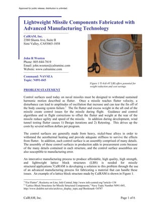
Figure 1 Ti-6Al-4V LBS offers potential for
weight reduction and cost savings.
PROBLEM STATEMENT
Control surfaces used today on naval missiles must be designed to withstand sustained
harmonic motion described as flutter. Once a missile reaches flutter velocity, a
disturbance can lead to amplitudes of oscillation that increase and can tear the fin off of
the body causing system failure.1 The fin flutter and excess weight in the aft end of the
missile create control issues for the missile during flight. Guidance and control
algorithms and in flight corrections to offset the flutter and weight at the rear of the
missile reduce agility and speed of the missile. In addition during development, wind
tunnel testing flutter causes 1) Design iterations and 2) Retesting. This drives up the
costs by several million dollars per program.
The control surfaces are generally made from heavy, nickel-base alloys in order to
withstand the aerothermal heating and provide adequate stiffness to survive the effects
from flutter. In addition, each control surface is an assembly comprised of many details.
The assembly of these control surfaces in production adds to procurement costs because
of the many details contained in each structure, and the control surface assemblies are
also susceptible to manufacturing error.
An innovative manufacturing process to produce affordable, high quality, high strength,
and lightweight lattice block structures (LBS) is needed for missile
structural applications.2CalRAM is developing a solution to this problem through the use
of an advanced manufacturing process for fabricating a material that can handle these
issues. An example of a lattice block structure made by CalRAM is shown in Figure 1.
1
“Fin Flutter”, Rocketry on Line, Info Central, http://www.info-central.org/?article=138
2
“Lattice Block Structures for Missile Structural Components,” Navy Topic Number N091-045,
http://www.dodsbir.net/sitis/archives_display_topic.asp?Bookmark=34787
CalRAM, Inc. Page 1 of 6
2. Approved for public release; distribution is unlimited.
WHO CAN BENEFIT?
Integrated Warfare Systems (IWS) 3, Standard Missile, Acquisition Category (ACAT) IV
is the original sponsor of this Small Business Innovation Research (SBIR) technology
development with the Standard Missile 3 (SM-3) and SM-6 being the initial transition
targets. CalRAM has also been invited to become a Raytheon (RMS) component
supplier.Several air and surface launched tactical missile programs are potential future
transition targets.Additional opportunities exist where gamma titanium aluminide is the
desired material, but producibility issues arise from machining.CalRAM’s use of an
Electron Beam Melted (EBM) manufacturing process alleviates this situation. Parts, such
as, low-pressure turbine blades, exhaust manifolds, and valve stems for combustion
engines are a few examples.
CalRAM already manufactures electron beam melted (EBM) components for the
Department of Defense (DoD) and several of the aerospace primes. This includes
components for the Navy Unmanned Combat Aerial System (UCAS)3 and the Joint
Strike Fighter (JSF). CalRAM has provided several components to enable the
development of the Army's Excalibur munitions program. In summary, platforms that
require complex, titanium components will benefit from this technology. Eventually,
platforms that use nickel-base superalloys will also benefit.
BASELINE TECHNOLOGY
Today, the missile platforms RMS and others build for the Navy use fins and other
control surfaces made from nickel-base alloys in order to withstand aerothermal heating
and help with flutter control. Although these components perform well they are
expensive to machine and are heavy. Gamma Titanium Aluminide (TiAl), which is half
as heavy as nickel-base alloys – density of 4.0 g/cc vs. 8.4 g/cc, is a viable material
substitution for many of these applications; however, it is very difficult to fabricate with
traditional manufacturing approaches, i.e., casting or machining forgings. EBM
manufacturing offers the potential to produce net or near-net shape gamma TiAl requiring
very little machining, resulting in significant weight savings, plus, by incorporating LBS,
additional weight savings and improved specific stiffness is possible. Finally, by making
a single piece fin assembly costs are also reduced.
TECHNOLOGY DESCRIPTION
EBM manufacturing is a net or near-net shape, fabrication process that builds
structuralmetal parts directly from a computer aided design (CAD) file. Based on
technology developed in the 1980's for “rapid prototyping” plastic parts, the process
begins by taking the CAD file and electronically slices it into layers approximately 100
3
John Wooten, Carolyn Uwate, Parviz Yavari, “Electron Beam Melting Manufacturing of Flight Hardware
for the Navy UCAS Program”, Aeromat, Dayton, OH, 2009
CalRAM, Inc. Page 2 of 6
3. Approved for public release; distribution is unlimited.
microns (0.004”) thick. The part is built directly from this sliced, CAD file in the EBM
machine – no tooling is required. The process begins by loading powder in the hoppers.
Figure 2 shows a photograph of the inside of the machine. After the powder has been put
in the hoppers, a stainless steel “start plate” is placed in the powder bed between the
hoppers and the build chamber evacuated. Figure 3 shows a schematic of the machine.
When a good vacuum is reached, the electron beam is turned on and the start plate is
heated to approximately 700°C to 1000°C depending on the material being melted.
When the start plate reaches this temperature, the first layer of powder is spread across
the plate. The machine then heats the powder and melts it according to the sliced CAD
file. After this layer had been generated, the build is lowered a 100 microns, the next
layer of powder is spread, and the process is repeated. The process continues like this
until the entire build is finished. After it has finished and cooled back to room
temperature, the chamber is opened; the part is raised up and removed from the chamber.
The excess powder is grit blasted from the part and the powder is recycled. At this point
in the process – depending on the requirements – the part is either finished or it can be
post processed. Post processing may include such operations, as hot isostatic pressing,
machining, drilling, grinding, etc.
There are several advantages of utilizing the EBM process to build control surfaces from
gamma TiAl LBS. Figure 4 has been prepared to summarize the features, advantages and
benefits of the process.
As can be seen, gamma TiAl used as a LBS offers high specific stiffness, which will help
reduce the effects from flutter. The EBM manufacturing process has the ability to rapidly
build metal components directly from the CAD file. This eliminates the need for tooling
and allows for the immediate incorporation of design changes. Since the process builds
parts in thin layers, design features that normally would require several parts in order to
achieve a certain functionality can now be integrated into one piece. The thin layers also
allow for the rapid cooling of the melted material. This translates into excellent physical
and mechanical properties. Thus, the process is ideally suited for low volume or low-rate
manufacturing of complex parts or it is ideal for developing and validating a design
concept.
Figure 2 Photograph of the inside of Figure 3 Schematic of EBM
build chamber. process.
h f d
CalRAM, Inc. Page 3 of 6
4. Approved for public release; distribution is unlimited.
Features Advantages Benefits
Gamma TiAl LBS High specific stiffness reduces Makes the missile more agile and faster
control surface flutter because fewer corrections from guidance and
control are needed
No tooling needed • Allows for rapid parts • Delivery times dramatically shortened –
manufacturing and immediate from months to days.
incorporation of design changes • Design, fabrication, and inspection of
• Reduces cost for low-volume or tooling is eliminated reducing life-cycle costs
low-rate production
Parts are fabricated • Complex features can be easily • Enables structures to be built in one piece
one layer at a time incorporated that otherwise would require multiple
• Thin layers allow for rapid components and joining operations
solidification of power • Produces extremely fine microstructure that
results in excellent mechanical properties
Parts are built at No residual stress in part Eliminates the need for stress relieving heat
elevated temperatures treatments
Powder is recycled Lowers cost of parts •No distortion if parts are reheated
• Low “buy-to-fly” ratio, approximately 1.1
to 1 vs. 10 to 1 and for machined parts
Figure 4Table summarizing Features, Advantages, Benefits of the EBM Process. Since the process is net or
near-net shape, the low buy-to-fly offers the potential for enormous cost savings.
CURRENT STATE OF DEVELOPMENT
The EBM manufacturing process has been used for several years to manufacture Ti-6Al-
4V parts. CalRAM has built parts for the Navy UCAS, as well as several other programs,
that have flown (See Figure 5). If the part shown in Figure 5 had been made by
conventional manufacturing, several details would have to be made and then joined
together. As such, many of the benefits described above, are exhibited in this part. The
mechanical properties for Ti-6Al-4V are given in Figure 6. These properties exceed the
baseline room temperature tensile strength for annealed, wrought Ti-6Al-4V.
The current Phase II SBIR program is focused on developing a new titanium alloy that is
comprised of titanium, 48 percent aluminum, 2 percent niobium and 2 percent chromium.
This alloy, termed gamma TiAl, is desirable because of its good high temperature
strength (up to 1500°F), its low density (4.0 g/cm^2), and its good specific stiffness.
CalRAM conducted a feasibility demonstration of gamma TiAl under a DARPA
sponsored program. Using the results from that program as a starting point, CalRAM
initiated the development of process parameters for the manufacture of EBM gamma
TiAl. After conducting approximately 45 experimental builds, key processing parameters
were refined and selected. Tensile coupons built in the horizontal and vertical directions
were fabricated. Experiments were conducted to optimize the post-processing. A hot
isostatic pressing cycle of 4 hours at 1260°C at 25 ksi was chosen. The properties
developed to date compare favorably to conventionally fabricated gamma TiAl.
Components will be fabricated in the Option 1 and 2 Phases and tested at ATK-GASL to
the requirements provided by RMS. This will raise the Technology Readiness Level
(TRL) to 5. The TRL for EBM gamma TiAl as of October 2011 is 3.
CalRAM, Inc. Page 4 of 6
5. Approved for public release; distribution is unlimited.
Figure 5Photographs of EBM Ti-6Al-4V Warm Air Mixer built for Navy UCAS in various stages of
fabrication.
Tensile Strength Yield Strength Elongation (%) Reduction of Area (%)
Condition / Average Std. Dev. Average Std. Dev. Average Std. Dev. Average Std. Dev.
Direction (ksI) (ksi) (ksi) (ksi) (ksi) (ksi) (ksI) (ksi)
As-Deposited
X-Y 138.1 1.3 127.4 1.8 14.0 0.9 46.0 0.0
Z 140.7 0.4 126.1 1.2 12.0 0.9 35.0 2.6
HIP'd
X-Y 136.5 0.4 125.8 0.4 13.0 0.8 44.0 2.1
Z 139.0 1.2 125.7 0.9 14.0 0.6 37.0 2.2
Wrought Annealed
130 120 10
Ti-6Al-4V
Figure 6Room Temperature tensile data for EBM Ti-6Al-4V compared to standard Ti-6Al-4V
REFERENCES
Raytheon Missile Systems
Andrew Facciano, SM-3 and SM-6 Program, 520-665-5842
Doug Streeter, Excalibur Program, 520-545-6661
Northrop Grumman, Inc.
Carolyn Uwate, UCAS Program, 310-335-3161
Eric Fodran, Materials and Processes, 310-332-9042
Technical Point of Contact (TPOC) for Phase II SBIR, 301-227-4501
Arcam, AB (Equipment Manufacturer)
Magnus Rene, CEO, +46 31 710 32 00
WHEN THE TECHNOLOGY WILL BE READY FOR USE
At the completion of the Phase II SBIR in August 2013, structural missile components
will have been fabricated and tested to demonstrate the performance capability of gamma
CalRAM, Inc. Page 5 of 6
6. Approved for public release; distribution is unlimited.
TiAl Lattice Block Structures built by EBM manufacturing bringing the technology to a
TRL 5. These high-speed wind tunnel tests will have been conducted with oversight
from RMS who will have provided the testing conditions and requirements. At this point
the technology should be ready for implementation as missile system components.The
technology will be implemented into production over a two-three year time frame. Since
CalRAM is an AS9100 certified supplier of the EBM technology, it will be able to
support the low-volume or low-rate production needs and support ramp up requirements
by the acquisition of additional facilities.
ABOUT THE COMPANY
CalRAM was established in 2005 as a manufacturer of structural, metallic components
using additive manufacturing technology. After selecting EBM manufacturing as the
most promising technology, it became AS9100 certified and has been manufacturing
components using this technology since 2006 for the DoD, aerospace primes and others.
CalRAM presently has two EBM machines in a 2,200 square foot facility located in Simi
Valley, CA (See Figure 7).
CalRAM has provided EBM components to both the airframe primes, such as Northrop
Grumman and Raytheon, as well as the engine primes, such as Pratt & Whitney. In
addition, CalRAM has worked with key DoD agencies including, the NAVSEA at
Carderock and NAVAIR at Pax River, the AFRL at Wright-Patterson and Edwards AFB,
the Army at Redstone
Arsenal, and the Missile
Defense Agency at
Huntsville, Al.
Figure 7 Photograph of CalRAM's
EBM equipment
CalRAM, Inc. Page 6 of 6