SlideShare uma empresa Scribd logo
1 de 12
Baixar para ler offline
RADAR COMMUNICATION


ABSTRACT


This long range radar antenna (approximately 40m (130ft) in
diameter) rotates on a track to observe activities near the horizon.

RADAR is an acronym for Radio Detection And Ranging or

Radio Angle Detection And Ranging. It is a system used to
detect, range (determine the distance of), and map objects such as
aircraft and rain. Strong radio waves are transmitted, and a receiver
listens for any echoes. By analysing the reflected signal, the reflector
can be located, and sometimes identified. Although the amount of
signal returned is tiny, radio signals can easily be detected and
amplified.

Radar radio waves can be easily generated at any desired strength, detected at even tiny
powers, and then amplified many times. Thus radar is suited to detecting objects at very
large ranges where other reflections, like sound or visible light, would be too weak to
detect.


INTRODUCTION

          In 1887, the German physicist Heinrich Hertz began experimenting with radio
waves in his laboratory. He found that radio waves could be transmitted through different
types of materials, and were reflected by others. The existence of electromagnetic waves
was predicted earlier by James Clerk Maxwell, but it was Hertz who first succeeded in
generating and detecting radio waves experimentally.

          The scientists named CHRISTIAN HUELSMEYER , NIKOLA TESLA,

A.H.TAYLOR , L.C.YOUNG and ROBERT WATSON – WATT researched

and developed the fundamentals of RADAR technology in 1900’s.


   PRINCIPLES

Reflection
Description

Electromagnetic waves reflect (scatter) from any large change
in the dielectric or diamagnetic constants. This means that a
solid object in air or vacuum, or other significant change in
atomic density between object and what's surrounding it, will
usually scatter radar (radio) waves. This is particularly true of
electrically conductive materials such as metal and carbon
fiber, making radar particularly well suited to the detection of
aircraft and ships. Radar absorbing material, containing
resistive and sometimes magnetic substances, is used on
military vehicles to reduce radar reflection. This is the radio
equivalent of painting something a dark color.

Radar waves scatter in a variety of ways depending on the size (wavelength) of the radio
wave and the shape of the target. If the wavelength is much shorter than the target's size,
the wave will bounce off in a way similar to the way light bounces from a mirror. If the
wavelength is much longer than the size of the target, the target is polarized, like a dipole
antenna. This is described by Rayleigh Scattering (like the blue sky). When the two
length scales are comparable, there may be resonances. Early radars used very long
wavelengths that were larger than the targets and received a vague signal, whereas some
modern systems use shorter wavelengths (a few centimeters or shorter) that can image
objects as small as a loaf of bread or smaller.

Radio waves always reflect from curves and corners, in a way similar to glint from a
rounded piece of glass. The most reflective targets for short wavelengths have 90° angles
between the reflective surfaces. A surface consisting of three flat surfaces meeting at a
single corner, like the corner on a block, will always reflect directly back at the source.
These so-called corner cubes are commonly used as radar reflectors to make otherwise
difficult-to-detect objects easier to detect, and are often found on boats in order to
improve their detection in a rescue situation and reduce collisions. For generally the same
reasons objects attempting to avoid detection will angle their surfaces in a way to
eliminate inside corners and avoid surfaces and edges perpendicular to likely detection
directions, which leads to "odd" looking stealth aircraft. These precautions do not
completely eliminate reflection because of diffraction, especially at longer wavelengths.

Electromagnetic waves do not travel well underwater; thus for underwater applications,
sonar, based on sound waves, has to be used instead of radar.

Polarization

Polarization is the direction that the wave vibrates. Radars use horizontal, vertical, and
circular polarization to detect different types of reflections. For example, circular
polarization is used to minimize the interference caused by rain. Linear polarization
returns usually indicate metal surfaces, and help a search radar ignore rain. Random
polarization returns usually indicate a fractal surface like rock or dirt, and are used by
navigational radars.


                               Brightness can indicate reflectivity as in this 1960 weather
                               radar image. The radar's frequency, polarization, and
                               receiver determine what it can observe.


Distance measurement

Transit time

The easiest way to measure the range of an object is to broadcast a short pulse of radio
signal, and then time how long it takes for the reflection to return. The distance is one-
half the product of round trip time (because the signal has to travel to the target and then


back to the receiver) and the speed of the signal.                   Where c is the speed of
light in a vacuum, and τ is the round trip time. For RADAR the speed of signal is the
speed of light, making the round trip times very short for terrestrial ranging. For this
reason accurate distance measurement was difficult until the introduction of high
performance electronics, with older systems being accurate to perhaps a few percent.

The receiver cannot detect the return while the signal is being sent out – there is no way
to tell if the signal it hears is the original or the return. This means that a radar has a
distinct minimum range, which is the length of the pulse divided by the speed of light,

divided by two. In order to detect closer targets you have to use a shorter pulse length.

A similar effect imposes a specific maximum range as well. If the return from the target
comes in when the next pulse is being sent out, once again the receiver cannot tell the
difference. In order to maximize range, one wants to use longer times between pulses, the

inter-pulse time.

Frequency modulation

Another form of distance measuring radar is based on frequency modulation. Frequency
comparison between two signals is considerably more accurate, even with older
electronics, than timing the signal. By changing the frequency of the returned signal and
comparing that with the original, the difference can be easily measured.

This technique can be used in radar systems, and is often found in aircraft radar
altimeters. In these systems a "carrier" radar signal is frequency modulated in a
predictable way, typically varying up and down with a sine wave or sawtooth pattern at
audio frequencies. The signal is then sent out from one antenna and received on another,
typically located on the bottom of the aircraft, and the signal can be continuously
compared.

Since the signal frequency is changing, by the time the signal returns to the aircraft the
broadcast has shifted to some other frequency. The amount of that shift is greater over
longer times, so greater frequency differences mean a longer distance, the exact amount
being the "ramp speed" selected by the electronics. The amount of shift is therefore
directly related to the distance travelled, and can be displayed on an instrument. This
signal processing is similar to that used in speed detecting doppler radar. See the article
on continuous wave radar for more information.
Speed measurement

Speed is the change in distance to an object with respect to time. Thus the existing system
for measuring distance, combined with a little memory to see where the target last was, is
enough to measure speed. At one time the memory consisted of a user making grease-
pencil marks on the radar screen, and then calculating the speed using a slide rule.

However there is another effect that can be used to make much more accurate speed
measurements, and do so almost instantly (no memory required), known as the Doppler
effect. Practically every modern radar uses this principle in the pulse-doppler radar
system. It is also possible to make a radar without any pulsing, known as a continuous-
wave radar (CW radar), by sending out a very pure signal of a known frequency. Return
signals from targets are shifted away from this base frequency via the Doppler effect
enabling the calculation of the speed of the object relative to the radar.

POSITION MEASUREMENT

Radio signals broadcast from a single antenna will spread out in all directions, and
likewise a single antenna will receive signals equally from all directions. This leaves the
radar with the problem of deciding where the target object is located.

Early systems

Early systems tended to use omni-directional broadcast antennas, with directional
receiver antennas which were pointed in various directions. For instance the first
system to be deployed, Chain Home, used two straight antennas at right angles for
reception, each on a different display.

One serious limitation with this type of solution is that the broadcast is sent out in all
directions, so the amount of energy in the direction being examined is subject to the
inverse-square law. To get a reasonable amount of power on the "target", the broadcast
should also be steered. More modern systems used a steerable parabolic "dish" to create a
tight broadcast beam, typically using the same dish as the receiver. Such systems often
combined two radar frequencies in the same antenna in order to allow automatic steering,

or radar lock.
Not all radar antennas must rotate to scan the sky.


RADAR EQUATION

The amount of power Pr returning to the receiving antenna is given by the radar equation:


Where

Pt = transmitter power,

Gt = gain of transmitting antenna,

Ar = effective aperture (area) of receiving antenna,

σ = Radar Cross Section, or scattering coefficient of target,

Rt = distance from transmitter to target,

Rr = distance from target to receiver.

In the common case where the transmitter and receiver are at the same location, Rt = Rr
and the term Rt² Rr² can be replaced by R4, where R is the range. This yields:


This shows that the received power declines as the fourth power of the range, which
means that the reflected power from distant targets is very, very small.

Other mathematical developments in radar signal processing include time-frequency
analysis (Weyl Heisenberg or wavelet), as well as the chirplet transform which makes use
of the fact that radar returns from moving targets typically "chirp" (change their
frequency as a function of time, as does the sound of a bird or bat).
FREQUENCY BANDS

The traditional band names originated as code-names during World War II and are still in
military and aviation use throughout the world in the 21st century. They have been

adopted in the United States by the IEEE, and internationally by the ITU. Most countries
have additional regulations to control which parts of each band are available for civilian
or military use.

Other users of the radio spectrum, such as the broadcasting and electronic
countermeasures (ECM) industries, have replaced the traditional military designations
with their own systems.

Radar Frequency Bands

Band Frequency Wavelength
                                  Notes
Name Range          Range

HF     3-30 MHz 10-100 m          coastal radar systems;'high frequency'

                                  'P' for 'previous', applied retrospectively to early radar
P      < 300 MHz 1 m+
                                  systems

VHF    50330MHz 0.9-6 m           very long range,groundpenetrating;'veryhighfrequency'

       300-1000                   Very long range (e.g. ballistic early warning), ground
UHF                 0.3-1 m
       MHz                        penetrating; 'ultra high frequency'

                                  long range air traffic control and surveillance; 'L' for
L      1-2 GHz      15-30 cm
                                  'long'

                                  terminal air traffic control, long range weather, marine
S      2-4 GHz      7.5-15 cm
                                  radar; 'S' for 'short'

                                  a compromise (hence 'C') between X and S bands;
C      4-8 GHz      3.75-7.5 cm
                                  weather

X      8-12 GHz     2.5-3.75 cm missile guidance, marine radar, weather; in the USA the
                                  narrow range 10.525GHz ±25MHz is used for airport
radar.

                                  high-resolution mapping, satellite altimetry; frequency
Ku     12-18 GHz 1.67-2.5 cm
                                  just under K band (hence 'u')

                                  Mapping, short range, airport surveillance; frequency
                                  just above K band (hence 'a') Photo radar, used to
Ka     27-40 GHz 0.75-1.11 cm
                                  trigger cameras which take pictures of license plates of
                                  cars running red lights, operates at 34.300 ± 0.100 GHz.

mm     40-300 GHz 1 - 7.5mm       'millimetre' band, subdivided as below

V      40-75 GHz 4.0 - 7.5 mm

                                  used as a visual sensor for experimental autonomous
W      75-110 GHz 2.7 - 4.0 mm
                                  vehicles, high-resolution meterological observation


SPECIFIC RADAR SYSTEMS

Active Electronically Scanned Array (AESA)

An Active Electronically Scanned Array (AESA) is a revolutionary type of radar
whose transmitter and receiver functions are composed of numerous small
transmit/receive (T/R) modules that each scan a small fixed area, negating the need for a
moving antenna. AESA radars feature short to instantaneous (millisecond) scanning rates
and have desirable low-probability of intercept characteristics

Continuous-wave radar

Continuous-wave radar system is a radar system where a continuous wave is transmitted
by one antenna and a second receives the radio energy reflected from an object.

Doppler radar as weather radar

Doppler radar uses the Doppler Effect to return additional information from a radar
system. The Doppler Effect shifts the frequency of the radar beam due to movement of
the "target", allowing for the direct and highly accurate measurement of speeds. Doppler
radars were originally developed for military radar systems, but have since become a part
of almost all radar systems, including weather radar and radar guns for traffic police and
sports

Millimeter cloud radar

The millimeter wave cloud radar (MMCR) is a remote sensing instrument that transmits a
radar pulse directly overhead to determine the tops and bottoms of clouds. It can also
serve as a type of Doppler radar in measuring up and down particle movements within a
cloud. Values that the radar measures are Doppler velocity, radar reflectivity, and spectral
width.


NEXRAD


NEXRAD Radar at NSSL

NEXRAD or Nexrad (the next-generation radar) is a network of Doppler radars
operated by the National Weather Service, an agency of NOAA, the National Oceanic
and Atmospheric Administration, in the United States. NEXRAD detects precipitation
and atmospheric movement or wind. It returns data which when processed can be
displayed in a mosaic map which shows patterns of precipitation and its movement. The
radar system operates in two basic modes, selectable by the operator: a slow-scanning
"clear-air mode" for analyzing air movements when there is little or no activity in the
area, and a "precipitation mode" with a faster scan time to do traditional storm tracking.


Passive radar

Passive Radar is type of radar system which uses one or more receivers, but lacks an
active transmitter. The system detects ambient radio signals emanating from nearby radio
transmitters. The receiver is either bistatic or multistatic, since it is positioned elsewhere.
The system is not restricted to one receiver—several receiver systems may be operated in
conjunction with one or many transmitters.


Pulse-Doppler radar

Radar gun traffic and sports radars


U.S. Army soldier uses a radar gun to catch speeding
violators at Tallil Air Base, Iraq.

A radar gun is a small Doppler radar used to detect the
speed of objects. A radar gun does not return position or
power information. It relies on the Doppler Effect applied to

a radar beam to measure the speed of objects it is pointed at.

Radar guns may be hand-held or vehicle-mounted. Common uses include traffic speed
law enforcement, and measuring the speed of balls in sports.

Secondary surveillance radar (SSR).
Synthetic aperture radar

               The surface of Venus, as imaged by the Magellan probe using SAR,

Synthetic aperture radar (SAR) is a form of radar in which sophisticated post-
processing of radar data is used to produce a very narrow effective beam. It can only be
used by moving instruments over relatively immobile targets, but it has seen wide
applications in remote sensing and mapping.


X-band radar

Mais conteúdo relacionado

Mais procurados

Radar Powerpoint
Radar PowerpointRadar Powerpoint
Radar PowerpointRyan rice
 
Chapter 3- pulsed radar system and MTI
Chapter 3- pulsed radar system and MTIChapter 3- pulsed radar system and MTI
Chapter 3- pulsed radar system and MTIRima Assaf
 
Dipole antenna
Dipole antennaDipole antenna
Dipole antennamahendra v
 
Components of a Pulse Radar System
Components of a Pulse Radar SystemComponents of a Pulse Radar System
Components of a Pulse Radar SystemÜlger Ahmet
 
Study of Radar System PPT
Study of Radar System PPTStudy of Radar System PPT
Study of Radar System PPTAtul Sharma
 
Radar Systems- Unit-II : CW and Frequency Modulated Radar
Radar Systems- Unit-II : CW and Frequency Modulated RadarRadar Systems- Unit-II : CW and Frequency Modulated Radar
Radar Systems- Unit-II : CW and Frequency Modulated RadarVenkataRatnam14
 
Radar fundamentals
Radar fundamentalsRadar fundamentals
Radar fundamentalsAli Sufyan
 
Radar 2009 a 11 waveforms and pulse compression
Radar 2009 a 11 waveforms and pulse compressionRadar 2009 a 11 waveforms and pulse compression
Radar 2009 a 11 waveforms and pulse compressionForward2025
 
Radio and Radar: Radar
Radio and Radar: Radar Radio and Radar: Radar
Radio and Radar: Radar Jess Peters
 

Mais procurados (20)

Radar Powerpoint
Radar PowerpointRadar Powerpoint
Radar Powerpoint
 
Chapter 3- pulsed radar system and MTI
Chapter 3- pulsed radar system and MTIChapter 3- pulsed radar system and MTI
Chapter 3- pulsed radar system and MTI
 
Radar communication
Radar communicationRadar communication
Radar communication
 
Dipole antenna
Dipole antennaDipole antenna
Dipole antenna
 
Components of a Pulse Radar System
Components of a Pulse Radar SystemComponents of a Pulse Radar System
Components of a Pulse Radar System
 
Radar
RadarRadar
Radar
 
Study of Radar System PPT
Study of Radar System PPTStudy of Radar System PPT
Study of Radar System PPT
 
Radar communication
Radar communicationRadar communication
Radar communication
 
radar
radarradar
radar
 
Cw and fm cw radar
Cw and fm cw radarCw and fm cw radar
Cw and fm cw radar
 
Monopulse Radar
Monopulse RadarMonopulse Radar
Monopulse Radar
 
Radar Systems- Unit-II : CW and Frequency Modulated Radar
Radar Systems- Unit-II : CW and Frequency Modulated RadarRadar Systems- Unit-II : CW and Frequency Modulated Radar
Radar Systems- Unit-II : CW and Frequency Modulated Radar
 
Radar fundamentals
Radar fundamentalsRadar fundamentals
Radar fundamentals
 
RADAR
RADARRADAR
RADAR
 
Radar 2009 a 11 waveforms and pulse compression
Radar 2009 a 11 waveforms and pulse compressionRadar 2009 a 11 waveforms and pulse compression
Radar 2009 a 11 waveforms and pulse compression
 
Dipole Antenna
Dipole AntennaDipole Antenna
Dipole Antenna
 
Pulse Doppler Radar
Pulse Doppler RadarPulse Doppler Radar
Pulse Doppler Radar
 
radar basics
radar basicsradar basics
radar basics
 
radar technology
radar technologyradar technology
radar technology
 
Radio and Radar: Radar
Radio and Radar: Radar Radio and Radar: Radar
Radio and Radar: Radar
 

Destaque

Orientation of Radar Antenna
Orientation of Radar AntennaOrientation of Radar Antenna
Orientation of Radar AntennaIOSR Journals
 
Moving target indicator radar (mti)part2
Moving target indicator radar (mti)part2Moving target indicator radar (mti)part2
Moving target indicator radar (mti)part2abdulrehmanali
 
Monopulse tracking radar
Monopulse tracking radarMonopulse tracking radar
Monopulse tracking radarAshok Selsan
 
Radar 2009 a 12 clutter rejection basics and mti
Radar 2009 a 12 clutter rejection   basics and mtiRadar 2009 a 12 clutter rejection   basics and mti
Radar 2009 a 12 clutter rejection basics and mtiForward2025
 
14. doppler radar and mti 2014
14. doppler radar and mti 201414. doppler radar and mti 2014
14. doppler radar and mti 2014Lohith Kumar
 
Radar 2009 a 13 clutter rejection doppler filtering
Radar 2009 a 13 clutter rejection   doppler filteringRadar 2009 a 13 clutter rejection   doppler filtering
Radar 2009 a 13 clutter rejection doppler filteringForward2025
 
Phased array antenna
Phased array antennaPhased array antenna
Phased array antennaShaveta Banda
 
A Tutorial on Radar System Engineering
A Tutorial on Radar System EngineeringA Tutorial on Radar System Engineering
A Tutorial on Radar System EngineeringTBSS Group
 

Destaque (18)

Radar ppt
Radar pptRadar ppt
Radar ppt
 
RADAR Basics
RADAR BasicsRADAR Basics
RADAR Basics
 
Radar
RadarRadar
Radar
 
RADAR AND ANTENNA
RADAR AND ANTENNARADAR AND ANTENNA
RADAR AND ANTENNA
 
Radar
RadarRadar
Radar
 
Military Radar
Military RadarMilitary Radar
Military Radar
 
Military radar
Military radarMilitary radar
Military radar
 
Orientation of Radar Antenna
Orientation of Radar AntennaOrientation of Radar Antenna
Orientation of Radar Antenna
 
Moving target indicator radar (mti)part2
Moving target indicator radar (mti)part2Moving target indicator radar (mti)part2
Moving target indicator radar (mti)part2
 
Radar
RadarRadar
Radar
 
Monopulse tracking radar
Monopulse tracking radarMonopulse tracking radar
Monopulse tracking radar
 
Radar 2009 a 12 clutter rejection basics and mti
Radar 2009 a 12 clutter rejection   basics and mtiRadar 2009 a 12 clutter rejection   basics and mti
Radar 2009 a 12 clutter rejection basics and mti
 
14. doppler radar and mti 2014
14. doppler radar and mti 201414. doppler radar and mti 2014
14. doppler radar and mti 2014
 
Radar 2009 a 13 clutter rejection doppler filtering
Radar 2009 a 13 clutter rejection   doppler filteringRadar 2009 a 13 clutter rejection   doppler filtering
Radar 2009 a 13 clutter rejection doppler filtering
 
Phased array antenna
Phased array antennaPhased array antenna
Phased array antenna
 
Radar Basics
Radar BasicsRadar Basics
Radar Basics
 
A Tutorial on Radar System Engineering
A Tutorial on Radar System EngineeringA Tutorial on Radar System Engineering
A Tutorial on Radar System Engineering
 
Radar Application
Radar ApplicationRadar Application
Radar Application
 

Semelhante a Radar communication 2

Introduction to radars
Introduction to radarsIntroduction to radars
Introduction to radarsTARUN CHOPRA
 
Radiolocating
RadiolocatingRadiolocating
Radiolocatingrf1002
 
132777 633668725440151250
132777 633668725440151250132777 633668725440151250
132777 633668725440151250RRFF
 
PROJECT REPORT1 (1) new
PROJECT REPORT1 (1) newPROJECT REPORT1 (1) new
PROJECT REPORT1 (1) newAnkita Badal
 
Surveying ii ajith sir class5
Surveying ii ajith sir class5Surveying ii ajith sir class5
Surveying ii ajith sir class5SHAMJITH KM
 
CHAPTER 1 PRINCIPLES OF RADAR.pptx
CHAPTER 1 PRINCIPLES OF RADAR.pptxCHAPTER 1 PRINCIPLES OF RADAR.pptx
CHAPTER 1 PRINCIPLES OF RADAR.pptxJaamacAbdikhayr
 
Chapter 1-generality
Chapter 1-generalityChapter 1-generality
Chapter 1-generalityRima Assaf
 
Microwave remote sensing
Microwave remote sensingMicrowave remote sensing
Microwave remote sensingRohit Kumar
 
UNIT - 1principlea of radar information.pptx
UNIT - 1principlea of radar information.pptxUNIT - 1principlea of radar information.pptx
UNIT - 1principlea of radar information.pptxgurramkondasadaf
 
J0412261066
J0412261066J0412261066
J0412261066IOSR-JEN
 
Radar remote sensing, P K MANI
Radar remote sensing, P K MANIRadar remote sensing, P K MANI
Radar remote sensing, P K MANIP.K. Mani
 
Missile Defense Radar..... (1) [Autosaved].pptx
Missile Defense Radar..... (1) [Autosaved].pptxMissile Defense Radar..... (1) [Autosaved].pptx
Missile Defense Radar..... (1) [Autosaved].pptxKamrulIslam21937
 

Semelhante a Radar communication 2 (20)

Introduction to radars
Introduction to radarsIntroduction to radars
Introduction to radars
 
Radiolocating
RadiolocatingRadiolocating
Radiolocating
 
PPT.ppt
PPT.pptPPT.ppt
PPT.ppt
 
Microwave Band
Microwave BandMicrowave Band
Microwave Band
 
132777 633668725440151250
132777 633668725440151250132777 633668725440151250
132777 633668725440151250
 
Radar ece
Radar eceRadar ece
Radar ece
 
PROJECT REPORT1 (1) new
PROJECT REPORT1 (1) newPROJECT REPORT1 (1) new
PROJECT REPORT1 (1) new
 
Surveying ii ajith sir class5
Surveying ii ajith sir class5Surveying ii ajith sir class5
Surveying ii ajith sir class5
 
CHAPTER 1 PRINCIPLES OF RADAR.pptx
CHAPTER 1 PRINCIPLES OF RADAR.pptxCHAPTER 1 PRINCIPLES OF RADAR.pptx
CHAPTER 1 PRINCIPLES OF RADAR.pptx
 
RARDAR Material
RARDAR MaterialRARDAR Material
RARDAR Material
 
Chapter 1-generality
Chapter 1-generalityChapter 1-generality
Chapter 1-generality
 
Microwave remote sensing
Microwave remote sensingMicrowave remote sensing
Microwave remote sensing
 
UNIT - 1principlea of radar information.pptx
UNIT - 1principlea of radar information.pptxUNIT - 1principlea of radar information.pptx
UNIT - 1principlea of radar information.pptx
 
Report on radar
Report on radarReport on radar
Report on radar
 
J0412261066
J0412261066J0412261066
J0412261066
 
Radar by abhishek mahajan
Radar by abhishek mahajanRadar by abhishek mahajan
Radar by abhishek mahajan
 
Radar remote sensing, P K MANI
Radar remote sensing, P K MANIRadar remote sensing, P K MANI
Radar remote sensing, P K MANI
 
Fdp radar
Fdp radarFdp radar
Fdp radar
 
Missile Defense Radar..... (1) [Autosaved].pptx
Missile Defense Radar..... (1) [Autosaved].pptxMissile Defense Radar..... (1) [Autosaved].pptx
Missile Defense Radar..... (1) [Autosaved].pptx
 
Radar.pptx
Radar.pptxRadar.pptx
Radar.pptx
 

Último

AWS Community Day CPH - Three problems of Terraform
AWS Community Day CPH - Three problems of TerraformAWS Community Day CPH - Three problems of Terraform
AWS Community Day CPH - Three problems of TerraformAndrey Devyatkin
 
Boost Fertility New Invention Ups Success Rates.pdf
Boost Fertility New Invention Ups Success Rates.pdfBoost Fertility New Invention Ups Success Rates.pdf
Boost Fertility New Invention Ups Success Rates.pdfsudhanshuwaghmare1
 
Tata AIG General Insurance Company - Insurer Innovation Award 2024
Tata AIG General Insurance Company - Insurer Innovation Award 2024Tata AIG General Insurance Company - Insurer Innovation Award 2024
Tata AIG General Insurance Company - Insurer Innovation Award 2024The Digital Insurer
 
🐬 The future of MySQL is Postgres 🐘
🐬  The future of MySQL is Postgres   🐘🐬  The future of MySQL is Postgres   🐘
🐬 The future of MySQL is Postgres 🐘RTylerCroy
 
Apidays New York 2024 - The value of a flexible API Management solution for O...
Apidays New York 2024 - The value of a flexible API Management solution for O...Apidays New York 2024 - The value of a flexible API Management solution for O...
Apidays New York 2024 - The value of a flexible API Management solution for O...apidays
 
Why Teams call analytics are critical to your entire business
Why Teams call analytics are critical to your entire businessWhy Teams call analytics are critical to your entire business
Why Teams call analytics are critical to your entire businesspanagenda
 
Artificial Intelligence Chap.5 : Uncertainty
Artificial Intelligence Chap.5 : UncertaintyArtificial Intelligence Chap.5 : Uncertainty
Artificial Intelligence Chap.5 : UncertaintyKhushali Kathiriya
 
Connector Corner: Accelerate revenue generation using UiPath API-centric busi...
Connector Corner: Accelerate revenue generation using UiPath API-centric busi...Connector Corner: Accelerate revenue generation using UiPath API-centric busi...
Connector Corner: Accelerate revenue generation using UiPath API-centric busi...DianaGray10
 
Apidays Singapore 2024 - Building Digital Trust in a Digital Economy by Veron...
Apidays Singapore 2024 - Building Digital Trust in a Digital Economy by Veron...Apidays Singapore 2024 - Building Digital Trust in a Digital Economy by Veron...
Apidays Singapore 2024 - Building Digital Trust in a Digital Economy by Veron...apidays
 
HTML Injection Attacks: Impact and Mitigation Strategies
HTML Injection Attacks: Impact and Mitigation StrategiesHTML Injection Attacks: Impact and Mitigation Strategies
HTML Injection Attacks: Impact and Mitigation StrategiesBoston Institute of Analytics
 
Cloud Frontiers: A Deep Dive into Serverless Spatial Data and FME
Cloud Frontiers:  A Deep Dive into Serverless Spatial Data and FMECloud Frontiers:  A Deep Dive into Serverless Spatial Data and FME
Cloud Frontiers: A Deep Dive into Serverless Spatial Data and FMESafe Software
 
ProductAnonymous-April2024-WinProductDiscovery-MelissaKlemke
ProductAnonymous-April2024-WinProductDiscovery-MelissaKlemkeProductAnonymous-April2024-WinProductDiscovery-MelissaKlemke
ProductAnonymous-April2024-WinProductDiscovery-MelissaKlemkeProduct Anonymous
 
Bajaj Allianz Life Insurance Company - Insurer Innovation Award 2024
Bajaj Allianz Life Insurance Company - Insurer Innovation Award 2024Bajaj Allianz Life Insurance Company - Insurer Innovation Award 2024
Bajaj Allianz Life Insurance Company - Insurer Innovation Award 2024The Digital Insurer
 
MINDCTI Revenue Release Quarter One 2024
MINDCTI Revenue Release Quarter One 2024MINDCTI Revenue Release Quarter One 2024
MINDCTI Revenue Release Quarter One 2024MIND CTI
 
presentation ICT roal in 21st century education
presentation ICT roal in 21st century educationpresentation ICT roal in 21st century education
presentation ICT roal in 21st century educationjfdjdjcjdnsjd
 
Data Cloud, More than a CDP by Matt Robison
Data Cloud, More than a CDP by Matt RobisonData Cloud, More than a CDP by Matt Robison
Data Cloud, More than a CDP by Matt RobisonAnna Loughnan Colquhoun
 
Artificial Intelligence: Facts and Myths
Artificial Intelligence: Facts and MythsArtificial Intelligence: Facts and Myths
Artificial Intelligence: Facts and MythsJoaquim Jorge
 
Apidays New York 2024 - The Good, the Bad and the Governed by David O'Neill, ...
Apidays New York 2024 - The Good, the Bad and the Governed by David O'Neill, ...Apidays New York 2024 - The Good, the Bad and the Governed by David O'Neill, ...
Apidays New York 2024 - The Good, the Bad and the Governed by David O'Neill, ...apidays
 
Apidays New York 2024 - Scaling API-first by Ian Reasor and Radu Cotescu, Adobe
Apidays New York 2024 - Scaling API-first by Ian Reasor and Radu Cotescu, AdobeApidays New York 2024 - Scaling API-first by Ian Reasor and Radu Cotescu, Adobe
Apidays New York 2024 - Scaling API-first by Ian Reasor and Radu Cotescu, Adobeapidays
 
Boost PC performance: How more available memory can improve productivity
Boost PC performance: How more available memory can improve productivityBoost PC performance: How more available memory can improve productivity
Boost PC performance: How more available memory can improve productivityPrincipled Technologies
 

Último (20)

AWS Community Day CPH - Three problems of Terraform
AWS Community Day CPH - Three problems of TerraformAWS Community Day CPH - Three problems of Terraform
AWS Community Day CPH - Three problems of Terraform
 
Boost Fertility New Invention Ups Success Rates.pdf
Boost Fertility New Invention Ups Success Rates.pdfBoost Fertility New Invention Ups Success Rates.pdf
Boost Fertility New Invention Ups Success Rates.pdf
 
Tata AIG General Insurance Company - Insurer Innovation Award 2024
Tata AIG General Insurance Company - Insurer Innovation Award 2024Tata AIG General Insurance Company - Insurer Innovation Award 2024
Tata AIG General Insurance Company - Insurer Innovation Award 2024
 
🐬 The future of MySQL is Postgres 🐘
🐬  The future of MySQL is Postgres   🐘🐬  The future of MySQL is Postgres   🐘
🐬 The future of MySQL is Postgres 🐘
 
Apidays New York 2024 - The value of a flexible API Management solution for O...
Apidays New York 2024 - The value of a flexible API Management solution for O...Apidays New York 2024 - The value of a flexible API Management solution for O...
Apidays New York 2024 - The value of a flexible API Management solution for O...
 
Why Teams call analytics are critical to your entire business
Why Teams call analytics are critical to your entire businessWhy Teams call analytics are critical to your entire business
Why Teams call analytics are critical to your entire business
 
Artificial Intelligence Chap.5 : Uncertainty
Artificial Intelligence Chap.5 : UncertaintyArtificial Intelligence Chap.5 : Uncertainty
Artificial Intelligence Chap.5 : Uncertainty
 
Connector Corner: Accelerate revenue generation using UiPath API-centric busi...
Connector Corner: Accelerate revenue generation using UiPath API-centric busi...Connector Corner: Accelerate revenue generation using UiPath API-centric busi...
Connector Corner: Accelerate revenue generation using UiPath API-centric busi...
 
Apidays Singapore 2024 - Building Digital Trust in a Digital Economy by Veron...
Apidays Singapore 2024 - Building Digital Trust in a Digital Economy by Veron...Apidays Singapore 2024 - Building Digital Trust in a Digital Economy by Veron...
Apidays Singapore 2024 - Building Digital Trust in a Digital Economy by Veron...
 
HTML Injection Attacks: Impact and Mitigation Strategies
HTML Injection Attacks: Impact and Mitigation StrategiesHTML Injection Attacks: Impact and Mitigation Strategies
HTML Injection Attacks: Impact and Mitigation Strategies
 
Cloud Frontiers: A Deep Dive into Serverless Spatial Data and FME
Cloud Frontiers:  A Deep Dive into Serverless Spatial Data and FMECloud Frontiers:  A Deep Dive into Serverless Spatial Data and FME
Cloud Frontiers: A Deep Dive into Serverless Spatial Data and FME
 
ProductAnonymous-April2024-WinProductDiscovery-MelissaKlemke
ProductAnonymous-April2024-WinProductDiscovery-MelissaKlemkeProductAnonymous-April2024-WinProductDiscovery-MelissaKlemke
ProductAnonymous-April2024-WinProductDiscovery-MelissaKlemke
 
Bajaj Allianz Life Insurance Company - Insurer Innovation Award 2024
Bajaj Allianz Life Insurance Company - Insurer Innovation Award 2024Bajaj Allianz Life Insurance Company - Insurer Innovation Award 2024
Bajaj Allianz Life Insurance Company - Insurer Innovation Award 2024
 
MINDCTI Revenue Release Quarter One 2024
MINDCTI Revenue Release Quarter One 2024MINDCTI Revenue Release Quarter One 2024
MINDCTI Revenue Release Quarter One 2024
 
presentation ICT roal in 21st century education
presentation ICT roal in 21st century educationpresentation ICT roal in 21st century education
presentation ICT roal in 21st century education
 
Data Cloud, More than a CDP by Matt Robison
Data Cloud, More than a CDP by Matt RobisonData Cloud, More than a CDP by Matt Robison
Data Cloud, More than a CDP by Matt Robison
 
Artificial Intelligence: Facts and Myths
Artificial Intelligence: Facts and MythsArtificial Intelligence: Facts and Myths
Artificial Intelligence: Facts and Myths
 
Apidays New York 2024 - The Good, the Bad and the Governed by David O'Neill, ...
Apidays New York 2024 - The Good, the Bad and the Governed by David O'Neill, ...Apidays New York 2024 - The Good, the Bad and the Governed by David O'Neill, ...
Apidays New York 2024 - The Good, the Bad and the Governed by David O'Neill, ...
 
Apidays New York 2024 - Scaling API-first by Ian Reasor and Radu Cotescu, Adobe
Apidays New York 2024 - Scaling API-first by Ian Reasor and Radu Cotescu, AdobeApidays New York 2024 - Scaling API-first by Ian Reasor and Radu Cotescu, Adobe
Apidays New York 2024 - Scaling API-first by Ian Reasor and Radu Cotescu, Adobe
 
Boost PC performance: How more available memory can improve productivity
Boost PC performance: How more available memory can improve productivityBoost PC performance: How more available memory can improve productivity
Boost PC performance: How more available memory can improve productivity
 

Radar communication 2

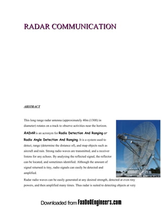
  • 1. RADAR COMMUNICATION ABSTRACT This long range radar antenna (approximately 40m (130ft) in diameter) rotates on a track to observe activities near the horizon. RADAR is an acronym for Radio Detection And Ranging or Radio Angle Detection And Ranging. It is a system used to detect, range (determine the distance of), and map objects such as aircraft and rain. Strong radio waves are transmitted, and a receiver listens for any echoes. By analysing the reflected signal, the reflector can be located, and sometimes identified. Although the amount of signal returned is tiny, radio signals can easily be detected and amplified. Radar radio waves can be easily generated at any desired strength, detected at even tiny powers, and then amplified many times. Thus radar is suited to detecting objects at very
  • 2. large ranges where other reflections, like sound or visible light, would be too weak to detect. INTRODUCTION In 1887, the German physicist Heinrich Hertz began experimenting with radio waves in his laboratory. He found that radio waves could be transmitted through different types of materials, and were reflected by others. The existence of electromagnetic waves was predicted earlier by James Clerk Maxwell, but it was Hertz who first succeeded in generating and detecting radio waves experimentally. The scientists named CHRISTIAN HUELSMEYER , NIKOLA TESLA, A.H.TAYLOR , L.C.YOUNG and ROBERT WATSON – WATT researched and developed the fundamentals of RADAR technology in 1900’s. PRINCIPLES Reflection
  • 3. Description Electromagnetic waves reflect (scatter) from any large change in the dielectric or diamagnetic constants. This means that a solid object in air or vacuum, or other significant change in atomic density between object and what's surrounding it, will usually scatter radar (radio) waves. This is particularly true of electrically conductive materials such as metal and carbon fiber, making radar particularly well suited to the detection of aircraft and ships. Radar absorbing material, containing resistive and sometimes magnetic substances, is used on military vehicles to reduce radar reflection. This is the radio equivalent of painting something a dark color. Radar waves scatter in a variety of ways depending on the size (wavelength) of the radio wave and the shape of the target. If the wavelength is much shorter than the target's size, the wave will bounce off in a way similar to the way light bounces from a mirror. If the wavelength is much longer than the size of the target, the target is polarized, like a dipole antenna. This is described by Rayleigh Scattering (like the blue sky). When the two length scales are comparable, there may be resonances. Early radars used very long wavelengths that were larger than the targets and received a vague signal, whereas some modern systems use shorter wavelengths (a few centimeters or shorter) that can image objects as small as a loaf of bread or smaller. Radio waves always reflect from curves and corners, in a way similar to glint from a rounded piece of glass. The most reflective targets for short wavelengths have 90° angles between the reflective surfaces. A surface consisting of three flat surfaces meeting at a single corner, like the corner on a block, will always reflect directly back at the source. These so-called corner cubes are commonly used as radar reflectors to make otherwise difficult-to-detect objects easier to detect, and are often found on boats in order to improve their detection in a rescue situation and reduce collisions. For generally the same reasons objects attempting to avoid detection will angle their surfaces in a way to eliminate inside corners and avoid surfaces and edges perpendicular to likely detection
  • 4. directions, which leads to "odd" looking stealth aircraft. These precautions do not completely eliminate reflection because of diffraction, especially at longer wavelengths. Electromagnetic waves do not travel well underwater; thus for underwater applications, sonar, based on sound waves, has to be used instead of radar. Polarization Polarization is the direction that the wave vibrates. Radars use horizontal, vertical, and circular polarization to detect different types of reflections. For example, circular polarization is used to minimize the interference caused by rain. Linear polarization returns usually indicate metal surfaces, and help a search radar ignore rain. Random polarization returns usually indicate a fractal surface like rock or dirt, and are used by navigational radars. Brightness can indicate reflectivity as in this 1960 weather radar image. The radar's frequency, polarization, and receiver determine what it can observe. Distance measurement Transit time The easiest way to measure the range of an object is to broadcast a short pulse of radio signal, and then time how long it takes for the reflection to return. The distance is one- half the product of round trip time (because the signal has to travel to the target and then back to the receiver) and the speed of the signal. Where c is the speed of light in a vacuum, and τ is the round trip time. For RADAR the speed of signal is the speed of light, making the round trip times very short for terrestrial ranging. For this
  • 5. reason accurate distance measurement was difficult until the introduction of high performance electronics, with older systems being accurate to perhaps a few percent. The receiver cannot detect the return while the signal is being sent out – there is no way to tell if the signal it hears is the original or the return. This means that a radar has a distinct minimum range, which is the length of the pulse divided by the speed of light, divided by two. In order to detect closer targets you have to use a shorter pulse length. A similar effect imposes a specific maximum range as well. If the return from the target comes in when the next pulse is being sent out, once again the receiver cannot tell the difference. In order to maximize range, one wants to use longer times between pulses, the inter-pulse time. Frequency modulation Another form of distance measuring radar is based on frequency modulation. Frequency comparison between two signals is considerably more accurate, even with older electronics, than timing the signal. By changing the frequency of the returned signal and comparing that with the original, the difference can be easily measured. This technique can be used in radar systems, and is often found in aircraft radar altimeters. In these systems a "carrier" radar signal is frequency modulated in a predictable way, typically varying up and down with a sine wave or sawtooth pattern at audio frequencies. The signal is then sent out from one antenna and received on another, typically located on the bottom of the aircraft, and the signal can be continuously compared. Since the signal frequency is changing, by the time the signal returns to the aircraft the broadcast has shifted to some other frequency. The amount of that shift is greater over longer times, so greater frequency differences mean a longer distance, the exact amount being the "ramp speed" selected by the electronics. The amount of shift is therefore directly related to the distance travelled, and can be displayed on an instrument. This signal processing is similar to that used in speed detecting doppler radar. See the article on continuous wave radar for more information.
  • 6. Speed measurement Speed is the change in distance to an object with respect to time. Thus the existing system for measuring distance, combined with a little memory to see where the target last was, is enough to measure speed. At one time the memory consisted of a user making grease- pencil marks on the radar screen, and then calculating the speed using a slide rule. However there is another effect that can be used to make much more accurate speed measurements, and do so almost instantly (no memory required), known as the Doppler effect. Practically every modern radar uses this principle in the pulse-doppler radar system. It is also possible to make a radar without any pulsing, known as a continuous- wave radar (CW radar), by sending out a very pure signal of a known frequency. Return signals from targets are shifted away from this base frequency via the Doppler effect enabling the calculation of the speed of the object relative to the radar. POSITION MEASUREMENT Radio signals broadcast from a single antenna will spread out in all directions, and likewise a single antenna will receive signals equally from all directions. This leaves the radar with the problem of deciding where the target object is located. Early systems Early systems tended to use omni-directional broadcast antennas, with directional receiver antennas which were pointed in various directions. For instance the first system to be deployed, Chain Home, used two straight antennas at right angles for reception, each on a different display. One serious limitation with this type of solution is that the broadcast is sent out in all directions, so the amount of energy in the direction being examined is subject to the inverse-square law. To get a reasonable amount of power on the "target", the broadcast should also be steered. More modern systems used a steerable parabolic "dish" to create a tight broadcast beam, typically using the same dish as the receiver. Such systems often combined two radar frequencies in the same antenna in order to allow automatic steering, or radar lock.
  • 7. Not all radar antennas must rotate to scan the sky. RADAR EQUATION The amount of power Pr returning to the receiving antenna is given by the radar equation: Where Pt = transmitter power, Gt = gain of transmitting antenna, Ar = effective aperture (area) of receiving antenna, σ = Radar Cross Section, or scattering coefficient of target, Rt = distance from transmitter to target, Rr = distance from target to receiver. In the common case where the transmitter and receiver are at the same location, Rt = Rr and the term Rt² Rr² can be replaced by R4, where R is the range. This yields: This shows that the received power declines as the fourth power of the range, which means that the reflected power from distant targets is very, very small. Other mathematical developments in radar signal processing include time-frequency analysis (Weyl Heisenberg or wavelet), as well as the chirplet transform which makes use of the fact that radar returns from moving targets typically "chirp" (change their frequency as a function of time, as does the sound of a bird or bat).
  • 8. FREQUENCY BANDS The traditional band names originated as code-names during World War II and are still in military and aviation use throughout the world in the 21st century. They have been adopted in the United States by the IEEE, and internationally by the ITU. Most countries have additional regulations to control which parts of each band are available for civilian or military use. Other users of the radio spectrum, such as the broadcasting and electronic countermeasures (ECM) industries, have replaced the traditional military designations with their own systems. Radar Frequency Bands Band Frequency Wavelength Notes Name Range Range HF 3-30 MHz 10-100 m coastal radar systems;'high frequency' 'P' for 'previous', applied retrospectively to early radar P < 300 MHz 1 m+ systems VHF 50330MHz 0.9-6 m very long range,groundpenetrating;'veryhighfrequency' 300-1000 Very long range (e.g. ballistic early warning), ground UHF 0.3-1 m MHz penetrating; 'ultra high frequency' long range air traffic control and surveillance; 'L' for L 1-2 GHz 15-30 cm 'long' terminal air traffic control, long range weather, marine S 2-4 GHz 7.5-15 cm radar; 'S' for 'short' a compromise (hence 'C') between X and S bands; C 4-8 GHz 3.75-7.5 cm weather X 8-12 GHz 2.5-3.75 cm missile guidance, marine radar, weather; in the USA the narrow range 10.525GHz ±25MHz is used for airport
  • 9. radar. high-resolution mapping, satellite altimetry; frequency Ku 12-18 GHz 1.67-2.5 cm just under K band (hence 'u') Mapping, short range, airport surveillance; frequency just above K band (hence 'a') Photo radar, used to Ka 27-40 GHz 0.75-1.11 cm trigger cameras which take pictures of license plates of cars running red lights, operates at 34.300 ± 0.100 GHz. mm 40-300 GHz 1 - 7.5mm 'millimetre' band, subdivided as below V 40-75 GHz 4.0 - 7.5 mm used as a visual sensor for experimental autonomous W 75-110 GHz 2.7 - 4.0 mm vehicles, high-resolution meterological observation SPECIFIC RADAR SYSTEMS Active Electronically Scanned Array (AESA) An Active Electronically Scanned Array (AESA) is a revolutionary type of radar whose transmitter and receiver functions are composed of numerous small transmit/receive (T/R) modules that each scan a small fixed area, negating the need for a moving antenna. AESA radars feature short to instantaneous (millisecond) scanning rates and have desirable low-probability of intercept characteristics Continuous-wave radar Continuous-wave radar system is a radar system where a continuous wave is transmitted by one antenna and a second receives the radio energy reflected from an object. Doppler radar as weather radar Doppler radar uses the Doppler Effect to return additional information from a radar system. The Doppler Effect shifts the frequency of the radar beam due to movement of the "target", allowing for the direct and highly accurate measurement of speeds. Doppler
  • 10. radars were originally developed for military radar systems, but have since become a part of almost all radar systems, including weather radar and radar guns for traffic police and sports Millimeter cloud radar The millimeter wave cloud radar (MMCR) is a remote sensing instrument that transmits a radar pulse directly overhead to determine the tops and bottoms of clouds. It can also serve as a type of Doppler radar in measuring up and down particle movements within a cloud. Values that the radar measures are Doppler velocity, radar reflectivity, and spectral width. NEXRAD NEXRAD Radar at NSSL NEXRAD or Nexrad (the next-generation radar) is a network of Doppler radars operated by the National Weather Service, an agency of NOAA, the National Oceanic and Atmospheric Administration, in the United States. NEXRAD detects precipitation and atmospheric movement or wind. It returns data which when processed can be displayed in a mosaic map which shows patterns of precipitation and its movement. The radar system operates in two basic modes, selectable by the operator: a slow-scanning
  • 11. "clear-air mode" for analyzing air movements when there is little or no activity in the area, and a "precipitation mode" with a faster scan time to do traditional storm tracking. Passive radar Passive Radar is type of radar system which uses one or more receivers, but lacks an active transmitter. The system detects ambient radio signals emanating from nearby radio transmitters. The receiver is either bistatic or multistatic, since it is positioned elsewhere. The system is not restricted to one receiver—several receiver systems may be operated in conjunction with one or many transmitters. Pulse-Doppler radar Radar gun traffic and sports radars U.S. Army soldier uses a radar gun to catch speeding violators at Tallil Air Base, Iraq. A radar gun is a small Doppler radar used to detect the speed of objects. A radar gun does not return position or power information. It relies on the Doppler Effect applied to a radar beam to measure the speed of objects it is pointed at. Radar guns may be hand-held or vehicle-mounted. Common uses include traffic speed law enforcement, and measuring the speed of balls in sports. Secondary surveillance radar (SSR).
  • 12. Synthetic aperture radar The surface of Venus, as imaged by the Magellan probe using SAR, Synthetic aperture radar (SAR) is a form of radar in which sophisticated post- processing of radar data is used to produce a very narrow effective beam. It can only be used by moving instruments over relatively immobile targets, but it has seen wide applications in remote sensing and mapping. X-band radar