Seth Forgosh - - Challenge 1 - Virtual Design Master
•
0 gostou•3,547 visualizações

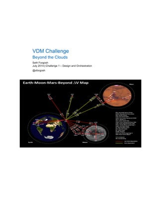
We thought that we had contained the outbreak; we were wrong. The outbreak is back with a vengeance and society as we knew it has fallen. Fortunately, Mr. Billionaire planned for this contingency. His space tourism company has built a large lunar base, designed to support what is left of the human race until the first colony can be established on Mars.

Recomendados
Mais conteúdo relacionado
Mais procurados
Mais procurados (17)
Destaque
Destaque (18)
Semelhante a Seth Forgosh - - Challenge 1 - Virtual Design Master
Semelhante a Seth Forgosh - - Challenge 1 - Virtual Design Master (20)
Mais de vdmchallenge
Mais de vdmchallenge (20)
Último
Último (20)
Seth Forgosh - - Challenge 1 - Virtual Design Master
- 1. VDM Challenge Beyond the Clouds Seth Forgosh July 2014 | Challenge 1 – Design and Orchestration @sforgosh
- 2. Page 2 Beyond the Clouds TABLE OF CONTENTS 1 Executive Summary .............................................................................................................................5 1.1 Scope.............................................................................................................................................................. 5 2 Current State.........................................................................................................................................5 2.1 LAN & WAN .................................................................................................................................................... 5 2.2 Physical Servers and Storage......................................................................................................................... 6 2.3 Power and Cooling.......................................................................................................................................... 6 2.4 Datacenter....................................................................................................................................................... 6 2.5 Site Locations.................................................................................................................................................. 6 3 Workload Definitions ...........................................................................................................................6 3.1 Applications and VM & Physical Sizing Estimates.......................................................................................... 6 3.2 Host Server Sizing and Information ................................................................................................................ 7 3.3 Storage Sizing and Information....................................................................................................................... 7 3.4 Network Sizing and Information ...................................................................................................................... 7 4 Active Directory Design.......................................................................................................................7 4.1 Domain Design................................................................................................................................................ 8 4.2 Naming Conventions....................................................................................................................................... 8 5 FlexPod Configuration.........................................................................................................................8 5.1 Physical Infrastructure................................................................................................................................... 10 5.2 Installation and Setup Instructions FAS8060 Systems ................................................................................. 16 6 ESXi Host Configuration....................................................................................................................19 6.1 Storage.......................................................................................................................................................... 19 6.2 Licensed Features......................................................................................................................................... 19 6.3 Time Configuration........................................................................................................................................ 20 6.4 DNS and Routing .......................................................................................................................................... 20 6.5 Virtual Machine Swap File Location.............................................................................................................. 20 6.6 Host Profiles.................................................................................................................................................. 20 7 vCenter and ESXi Cluster ..................................................................................................................20 7.1 vCenter.......................................................................................................................................................... 20 7.2 Datacenter..................................................................................................................................................... 20 7.3 Cluster........................................................................................................................................................... 20 7.4 HA ................................................................................................................................................................. 20
- 3. Page 3 Beyond the Clouds 7.5 DRS............................................................................................................................................................... 21 7.6 VASA............................................................................................................................................................. 21 7.7 VSC............................................................................................................................................................... 21 7.8 WFA .............................................................................................................................................................. 21 7.9 UCS Director................................................................................................................................................. 21 8 Storage ................................................................................................................................................22 8.1 Clustered Data OnTap Overview .................................................................................................................. 22 8.2 Storage Model Overview............................................................................................................................... 22 8.3 Protocols ....................................................................................................................................................... 22 9 Network ...............................................................................................................................................23 9.1 Cisco 6200 Fabric Interconnects................................................................................................................... 23 9.2 Cisco Nexus 2200 Fabric Extenders............................................................................................................. 23 9.3 Cisco Nexus 6000 switches .......................................................................................................................... 24 9.4 Virtual Switch Configuration.......................................................................................................................... 24 9.5 Virtual Machine Tempates ............................................................................................................................ 24 9.6 Virtual Machine Backup and Recovery ......................................................................................................... 24 10 Datacenter...........................................................................................................................................24 10.1 MDC 20-9 Specifications............................................................................................................................... 24 References ................................................................................................................................................28 LIST OF TABLES Table 1) Depots and corresponding Virtual Datacenters................................................................................................ 6 Table 2) FlexPod VLANs ................................................................................................................................................ 8 Table 3) FlexPod VSANs................................................................................................................................................ 9 Table 4) VMware virtual machines (VMs) created.......................................................................................................... 9 Table 5) Cisco Nexus 6001 A cabling information........................................................................................................ 11 Table 6) Cisco Nexus 6001 B cabling information........................................................................................................ 11 Table 7) Cisco Nexus 5596UP A cluster interconnect cabling information................................................................... 12 Table 8) Cisco Nexus 5596UP B cluster interconnect cabling information................................................................... 12 Table 9) NetApp controller A cabling information ......................................................................................................... 13 Table 10) NetApp controller B cabling information ....................................................................................................... 13 Table 11) Cisco UCS fabric interconnect A cabling information................................................................................... 14 Table 12) Cisco UCS fabric interconnect B cabling information................................................................................... 15 Table 13 ) FAS3250 card layout.................................................................................................................................. 15 Table 14) Cisco C220M3 card layout for Single-wire management ............................................................................ 15
- 4. Page 4 Beyond the Clouds LIST OF FIGURES Figure 1) FlexPod cabling diagram in clustered Data OnTap....................................................................................... 10 Figure 2) VMware vSphere Built on FlexPod................................................................................................................ 19 Figure 3) MDC20-9 9 Rack Container. ......................................................................................................................... 25 Figure 4) 250 kw Generator Container. ........................................................................................................................ 26 Figure 5) Redundant 35-Ton Chiller Container............................................................................................................. 26 Figure 6) Rack Diagram................................................................................................................................................ 27
- 5. Page 5 Beyond the Clouds 1 Executive Summary We thought that we had contained the outbreak; we were wrong. The outbreak is back with a vengeance and society as we knew it has fallen. Fortunately, Mr. Billionaire planned for this contingency. His space tourism company has built a large lunar base, designed to support what is left of the human race until the first colony can be established on Mars. 1.1 Scope Currently, there is only one space ship depot on earth, located in Cape Canaveral, Florida however three more are being built as quickly as possible with plans for additional depots to follow. Our task is to build a completely orchestrated infrastructure that is highly reliable and easily deployable to ensure that these sites are up and running as soon as possible. The application controlling the depot has the following requirements: • Client facing web layer • Message queuing middle tier • Database backend For this project, I’ve selected a FlexPod solution for compute, network and storage. This was done to provide flexability, repeatability, scalability and performance delivered as a converged infrastructure for this critical infrastructure. The FlexPod architecture is highly modular or “podlike.” Although each customer’s FlexPod unit varies in its exact configuration, after a FlexPod unit is built, it can easily be scaled as requirements and demand change. The unit can be scaled both up (adding resources to a FlexPod unit) and out (adding more FlexPod units). Specifically, FlexPod is a defined set of hardware and software that serves as an integrated foundation for both virtualized and nonvirtualized solutions. VMware vSphere ® built on FlexPod includes NetApp storage, NetApp Data ONTAP, Cisco networking, the Cisco Unified Computing System TM (Cisco UCS ® ), and VMware vSphere software in a single package. The design is flexible enough that the networking, computing, and storage can fit in one data center rack or be deployed according to a customer’s data center design. Port density enables the networking components to accommodate multiple configurations of this kind. A VMware vSphere 5.5 environment will be built on the FlexPod(s) to provide the required compute infrastructure to support each depot. A blade from the Cisco UCS component will be dedicated to supporting VMware vCenter Server while a second is allocated for the vCenter Database. Additionally, a Windows 2008 R2 Active Directory server will be built to support AD integrated SSO, DNS and DHCP. NetApp Workflow Automator (WFA) and Cisco UCS Director will be utilized to automate allocation of physical compute and storage. 2 Current State 2.1 LAN & WAN • LAN No current LAN infrastructure exists and will need to be built as part of the project. • WAN WAN termination points exist and internet access will be available once LAN network equipment is put in place and configured.
- 6. Page 6 Beyond the Clouds 2.2 Physical Servers and Storage • Servers No physical servers are currently in place. All compute will be deployed as part of the project. • Storege No storage infrastructure is currently in place. All storage will be deployed as part of the project. 2.3 Power and Cooling • Power Sufficient power circuits are available and cabling available on site. • Cooling Cooling provided by FAST Modile Data Centers 2.4 Datacenter • Mobile Datacenter(s) Nine (9) rack FAST Mobile Data Centers will be deployed to support this project to facilitate the capability to evacuate the site along with the IT infrastructure should the perimeter fall. 2.5 Site Locations There is currently only one depot though at least three (3) others will be built following this design with the potential for more. We will use an Alpha, Beta, Gamma, Delta naming convention for the depots as this will denote the order they come online and avoid locking them to a specific geographical location should the perimeter be breached and a site needs to be relocated. Table 1 shows the current depot as well as additional proposed sites and their corresponding Virtual Datacenter. Table 1) Depots and corresponding Virtual Datacenters Depot Location vCenter Virtual Datacenter Cape Canaveral Alpha TBD Beta TBD Gamma TBD Delta 3 Workload Definitions 3.1 Applications and VM & Physical Sizing Estimates • Windows 2008 RD Physical Domain Controller (DC): Quantity 4 (2 plus 2 spare) 1x Ciscso B22 M3, 2x Intel Xeon E5-2400 processors, 23GB RAM, 500GB RAID 1 internal storage • Linux Application Server VM: 2 vCPU, 2GB RAM, 50GB VMDK, 1 VNIC • Linux MySQL Database Server VM: 4 vCPU, 16GB RAM, 50GB VMDK, 2 VNIC • vCenter Server Appliance 5.5 Medium Inventory:
- 7. Page 7 Beyond the Clouds 4 vCPU, 24GB RAM, 500GB VMDK, 1 VNIC • Linux Web Server VM: 2 vCPU, 2GB RAM, 50GB VMDK, 1 VNIC • Linux Message Queue Server VM: 4vCPU, 16GB RAM, 50GB VMDK, 1 vNIC • WFA VM: 2vCPU, 16GB RAM, 50GB VMDK, 2vNIC • UCS Director VM: 4vCPU, 16GB RAM, 50GB VMDK, 2vNIC 3.2 Host Server Sizing and Information As part of the FlexPod confirguration, Cisco B200 M3 blades will be installed in each Cisco UCS 5100 Blade Server Chassis. Each chassis will be configured with 2x 2208 Fabric Extenders (FEX). Each blade will be configured with a VIC 1240 UCS Interface Adapter, 2x E502600 v2 CPUs and 512GB RAM. Storage for ESXi boot will be provided through FCoE LUNs provided by the NetApp Unified Storage Clustered Data OnTap (cDOT) system. Each blade is capable of providing up to 4 10GB UTAs with support for VMWare VMDirectPAth with vMotion. Additionally, a pair of Cisco UCS 6296UP 96-Port Fabric Interconnects will be utilized in this configuration. 3.3 Storage Sizing and Information As part of the FlexPod configuration, a four (4) node NetApp Clusterd Data OnTap (cDOT), configuration will be deployed. NetApp cDOT provides a unified scale out architecture providing ease of management, non-disruptive operation, storage efficiency and backup/recovery and business continuity. Configured as part of a FlexPod architecture, Storage Virtual Machines (SVMs) provide secure isolation for multi-tennant environments. The cDOT soulution for this project will be a four node configuration consisting of four FAS 8060 controllers with 2,753 PiB of effective SSD capacity in 20RU. Each node includes 4x10GbE ports and 4xUTA ports which will be configured with a 10GB FCoE personality. DR storage will be provided through the use of NetApp OnCloud for AWS utilizing Glacier storage. OnCloud is a software only implementation of the NetApp Data OnTap storage operating system. It is engineered to run on Amazon compute and provides the full range of Data OnTap functionality including SnapMirror and SnapVault. 3.4 Network Sizing and Information Cisco Nexus 5000 switches will handle the core of our infratstructure. A pair of Nexus 5627UP switches will each provide 48 ports 10GB Ethernet access, FEX aggregation, VXLAN segmentation and LAN-SAN convergence. Each depot will support a unique Class B range sub-netted into VLANs for traffic segmentation. DHCP reservations will be used for all VMs. 4 Active Directory Design Windows 2008 R2 Active Directory will be used in conjunction with VMware SSO to provide access to the vCenter infrastructure. AD LDAP will also be used to provide user authentication for the Depot application stack. As such, HA is a requirement and accordingly, two blades (one from each chassis) will be dedicated to AD/DNS/DHCP.
- 8. Page 8 Beyond the Clouds 4.1 Domain Design The top level domain will be named exodus.net and the primary AD site will be named exodus.net. Each depot will have an OU created as it comes online. This will allow any user with the proper credentials and rights to manage any depot from any location and maintain simplicity. Each depot will have the same DC configuration (2 DCs per depot) ensuring resiliency of the authentication infrastructure. Each DC will be configured as an authoritative time source and be synced to 0.north- america.pool.ntp.org, 1.north-america.pool.ntp.org, 2.north-america.pool.ntp.org and 3.north- america.pool.ntp.org. All services will sync to their depots local DCs to ensure consistent time. 4.2 Naming Conventions Location-TUUU## Location is the depot name, previously defined in Section 2.5. T denotes the type of VM, Production, Test and Development. UUU will be a either APP, WEB or SQL. And finally, ### will be a three digit counter to support multiple instences. 5 FlexPod Configuration This document provides details for configuring a fully redundant, highly available configuration for a FlexPod unit with clustered Data ONTAP storage. Therefore, reference is made to which component is being configured with each step, either 01, 02, 03 or 04. For example, node01, node02, node03 and node04 are used to identify the four NetApp storage controllers that are provisioned with this document, and Cisco Nexus A and Cisco Nexus B identify the pair of Cisco Nexus switches that are configured. The Cisco UCS fabric interconnects are similarly configured. Additionally, this document details the steps for provisioning multiple Cisco UCS hosts, and these are identified sequentially: AlphaVM-Host-Infra-01, AlphaVM-Host-Infra-02, and so on. Table 2 describes the VLANs necessary for deployment as outlined in this guide. The VM-Mgmt VLAN is used for management interfaces of the VMware vSphere hosts. Table 3 lists the virtual storage area networks (VSANs) necessary for deployment as outlined in this guide. Table 2) FlexPod VLANs VLAN Name VLAN Purpose VLAN ID Mgmt in band VLAN for in-band management interfaces 3175 Mgmt out of band VLAN for out-of-band management interfaces 3170 Native VLAN to which untagged frames are assigned 2 NFS VLAN for NFS traffic 3172 FCoE-A VLAN for FCoE traffic for fabric A 101 FCoE-B VLAN for FCoE traffic for fabric B 102
- 9. Page 9 Beyond the Clouds VLAN Name VLAN Purpose VLAN ID vMotion VLAN for movement of VMs from one host to another 3173 VM Traffic VLAN for VM application traffic 3174 Packet Control VLAN for Packet Control traffic (Cisco Nexus 1000v) 3176 Table 3) FlexPod VSANs VSAN Name VSAN Purpose VSAN ID VSAN A VSAN for fabric A traffic. ID matches FCoE-A VLAN 101 VSAN B VSAN for fabric A traffic. ID matches FCoE-B VLAN 102 Table 4) VMware virtual machines (VMs) created Virtual Machine Description Host Name vCenter Server Alpha-VC NetApp Virtual Storage Console Alpha-VSC NetApp OnCommand Unified Manager Alpha-OCUM NetApp VASA Provider Alpha-VASA
- 10. Page 10 Beyond the Clouds 5.1 Physical Infrastructure Figure 1 shows the cabling diagram for a FlexPod configuration using clustered Data ONTAP. Figure 1) FlexPod cabling diagram in clustered Data OnTap. The information provided in Table 5 through Table 20 corresponds to each connection shown in Figure 1. 17 FlexPod Data Center with VMware vSphere 5.1Update1 and Cisco Nexus 6000 Series Switches Physical Infrastructure Figure 2 FlexPod cabling diagram in clustered Data ONTAP. The information provided in Table 6 through Table 21 corresponds to each connection shown in Figure 2.
- 11. Page 11 Beyond the Clouds Table 5) Cisco Nexus 6001 A cabling information Local Device Local Port Connection Remote Device Remote Port Cabling Code Cisco Nexus 6001 A Eth1/1 10GbE NetApp controller A e3a 1 Eth1/2 10GbE NetApp controller B e3a 2 Eth1/11 10GbE Cisco UCS fabric interconnect A Eth1/19 3 Eth1/12 10GbE Cisco UCS fabric interconnect B Eth1/19 4 Eth1/14 10GbE Cisco Nexus 6001 B Eth1/14 6 Eth1/13 10GbE Cisco Nexus 6001 B Eth1/13 5 Eth1/15 GbE Cisco Nexus 1110-X A LOM A 7 Eth1/16 GbE Cisco Nexus 1110-X B LOM A 8 Eth1/31 10GbE Cisco UCS fabric interconnect A Eth1/31 9 Eth1/32 10GbE Cisco UCS fabric interconnect A Eth1/32 10 MGMT0 GbE GbE management switch Any Table 6) Cisco Nexus 6001 B cabling information Local Device Local Port Connection Remote Device Remote Port Cabling Code Cisco Nexus 6001 B Eth1/1 10GbE NetApp controller A e4a 11 Eth1/2 10GbE NetApp controller B e4a 12 Eth1/11 10GbE Cisco UCS fabric interconnect A Eth1/20 13 Eth1/12 10GbE Cisco UCS fabric interconnect B Eth1/20 14 Eth1/13 10GbE Cisco Nexus 6001 A Eth1/13 5 Eth1/14 10GbE Cisco Nexus 6001 A Eth1/14 6 Eth1/15 GbE Cisco Nexus 1110-X A LOM B 15 Eth1/16 GbE Cisco Nexus 1110-X B LOM B 16 Eth1/31 10GbE Cisco UCS fabric interconnect B Eth1/31 17 Eth1/32 10GbE Cisco UCS fabric interconnect B Eth1/32 18
- 12. Page 12 Beyond the Clouds Local Device Local Port Connection Remote Device Remote Port Cabling Code MGMT0 GbE GbE management switch Any Table 7) Cisco Nexus 5596UP A cluster interconnect cabling information Local Device Local Port Connection Remote Device Remote Port Cabling Code Cisco Nexus 5596UP A Eth1/1 10GbE NetApp controller A e1a 19 Eth1/2 10GbE NetApp controller B e1a 20 Eth1/41 10GbE Cisco Nexus 5596UP B Eth1/41 21 Eth1/42 10GbE Cisco Nexus 5596UP B Eth1/42 22 Eth1/43 10GbE Cisco Nexus 5596UP B Eth1/43 23 Eth1/44 10GbE Cisco Nexus 5596UP B Eth1/44 24 Eth1/45 10GbE Cisco Nexus 5596UP B Eth1/45 25 Eth1/46 10GbE Cisco Nexus 5596UP B Eth1/46 26 Eth1/47 10GbE Cisco Nexus 5596UP B Eth1/47 27 Eth1/48 10GbE Cisco Nexus 5596UP B Eth1/48 28 MGMT0 GbE GbE management switch Any Table 8) Cisco Nexus 5596UP B cluster interconnect cabling information Local Device Local Port Connection Remote Device Remote Port Cabling Code Cisco Nexus 5596UP B Eth1/1 10GbE NetApp controller A e2a 29 Eth1/2 10GbE NetApp controller B e2a 30 Eth1/41 10GbE Cisco Nexus 5596UP A Eth1/41 31 Eth1/42 10GbE Cisco Nexus 5596UP A Eth1/42 32 Eth1/43 10GbE Cisco Nexus 5596UP A Eth1/43 33 Eth1/44 10GbE Cisco Nexus 5596UP A Eth1/44 34 Eth1/45 10GbE Cisco Nexus 5596UP A Eth1/45 35
- 13. Page 13 Beyond the Clouds Local Device Local Port Connection Remote Device Remote Port Cabling Code Eth1/46 10GbE Cisco Nexus 5596UP A Eth1/46 36 Eth1/47 10GbE Cisco Nexus 5596UP A Eth1/47 37 Eth1/48 10GbE Cisco Nexus 5596UP A Eth1/48 38 MGMT0 GbE GbE management switch Any Table 9) NetApp controller A cabling information Local Device Local Port Connection Remote Device Remote Port Cabling Code NetApp controller A e0M 100MbE 100MbE management switch Any e0a GbE GbE management switch Any e0P GbE SAS shelves ACP port c0a 10GbE NetApp controller B c0a 41 c0b 10GbE NetApp controller B c0b 42 e1a 10GbE Cisco Nexus 5596UP A Eth1/1 19 e2a 10GbE Cisco Nexus 5596UP B Eth1/1 29 e3a 10GbE Cisco Nexus 6001 A Eth1/1 1 e4a 10GbE Cisco Nexus 6001 B Eth1/1 11 Table 10) NetApp controller B cabling information Local Device Local Port Connection Remote Device Remote Port Cabling Code NetApp controller B e0M 100MbE 100MbE management switch Any e0a GbE GbE management switch Any e0P GbE SAS shelves ACP port c0a 10GbE NetApp controller A c0a 41
- 14. Page 14 Beyond the Clouds Local Device Local Port Connection Remote Device Remote Port Cabling Code c0b 10GbE NetApp controller A c0b 42 e1a 10GbE Cisco Nexus 5596UP A Eth1/1 19 e2a 10GbE Cisco Nexus 5596UP B Eth1/1 29 e3a 10GbE Cisco Nexus 6001 A Eth1/1 1 e4a 10GbE Cisco Nexus 6001 B Eth1/1 11 Table 11) Cisco UCS fabric interconnect A cabling information Local Device Local Port Connection Remote Device Remote Port Cabling Code Cisco UCS fabric interconnect A Eth1/19 10GbE Cisco Nexus 6001 A Eth1/11 3 Eth1/20 10GbE Cisco Nexus 6001 B Eth1/11 13 Eth1/1 10GbE Cisco UCS Chassis 1 FEX A Port 1 31 Eth1/2 10GbE Cisco UCS Chassis 1 FEX A Port 2 32 Eth 1/3 10GbE Cisco Nexus 2232PP FEX A Port 2/1 33 Eth 1/4 10GbE Cisco Nexus 2232PP FEX A Port 2/2 34 Eth1/31 10GbE Cisco Nexus 6001 A Eth1/31 9 Eth1/32 10GbE Cisco Nexus 6001 B Eth1/32 10 MGMT0 GbE GbE management switch Any L1 GbE Cisco UCS fabric interconnect B L1 L2 GbE Cisco UCS fabric interconnect B L2
- 15. Page 15 Beyond the Clouds Table 12) Cisco UCS fabric interconnect B cabling information Local Device Local Port Connection Remote Device Remote Port Cabling Code Cisco UCS fabric interconnect B Eth1/19 10GbE Cisco Nexus 6001 A Eth1/12 4 Eth1/20 10GbE Cisco Nexus 6001 B Eth1/12 14 Eth1/1 10GbE Cisco UCS Chassis 1 FEX A Port 1 35 Eth1/2 10GbE Cisco UCS Chassis 1 FEX A Port 2 36 Eth 1/3 10GbE Cisco Nexus 2232PP FEX A Port 2/1 37 Eth 1/4 10GbE Cisco Nexus 2232PP FEX A Port 2/2 38 Eth1/31 10GbE Cisco Nexus 6001 A Eth1/31 17 Eth1/32 10GbE Cisco Nexus 6001 B Eth1/32 18 MGMT0 GbE GbE management switch Any L1 GbE Cisco UCS fabric interconnect B L1 L2 GbE Cisco UCS fabric interconnect B L2 Table 13 ) FAS3250 card layout Slot Part Number Description 1 X1117A-R6 NIC 2-port 10GbE (ports e1a and e1b) 2 X1117A-R6 NIC 2-port 10GbE (ports e2a and e2b) 3 X1140A-R6 Unified target 2-port 10GbE (ports e3a and e3b) 4 X1140A-R6 Unified target 2-port 10GbE (ports e4a and e4b) 5 X1971A-R5 Flash Cache™ – 512GB 6 X2065A-R6 SAS, 4-port, 6Gb Table 14) Cisco C220M3 card layout for Single-wire management Slot Part Number Description 1 Cisco UCS VIC1225 CNA 2-port 10GbE (ports 0 and 1)
- 16. Page 16 Beyond the Clouds 5.2 Installation and Setup Instructions FAS8060 Systems Install Hardware 1. Attach cable management tray. 2. Cable e0a through e0d on all controllers to switches. 3. Connect wrench ports to the management switch. 4. Connect GbE ports e0i and e0k to GbE data network switches. 5. Connect ports e0e|0e and e0g|0g to data switch. 6. Strap the cables to the cable management tray. 7. Cable both power supplies for each chassis.
- 17. Page 17 Beyond the Clouds Cable Storage
- 18. Page 18 Beyond the Clouds Complete System Setup
- 19. Page 19 Beyond the Clouds 6 ESXi Host Configuration Each host will be configured with ESXi 5.5 as noted below. 6.1 Storage NetApp Workflow Automator (WFA) will be used to provision several NFS datastores presented to each host supporting the management application infrastructure. WFA will be used to provision a NFS FlexVol containg all MySQL binaries which will be mounted to each MySQL database VM. WFA will be used to provision FC LUNs for each host boot drive. Figure 2) VMware vSphere Built on FlexPod. 6.2 Licensed Features Each host will be licensed with VMware vSphere Enterprise Plus 7 FlexPod Data Center with VMware vSphere 5.1Update1 and Cisco Nexus 6000 Series Switches computing, and storage can fit in one data center rack or be deployed according to a customer’s data center design. Port density enables the networking components to accommodate multiple configurations of this kind. One benefit of the FlexPod architecture is the ability to customize or “flex” the environment to suit a customer’s requirements. This is why the reference architecture detailed in this document highlights the resiliency, cost benefit, and ease of deployment of an FCoE-based storage solution. A storage system capable of serving multiple protocols across a single interface allows for customer choice and investment protection because it truly is a wire-once architecture. Figure 1 shows the VMware vSphere built on FlexPod components and the network connections for a configuration with FCoE-based storage. This design uses the Cisco Nexus® 6001, Cisco Nexus 2232PP FEX, and Cisco UCS C-Series and B-Series with the Cisco UCS virtual interface card (VIC) and the NetApp FAS family of storage controllers connected in a highly available design using Cisco Virtual PortChannels (vPCs). This infrastructure is deployed to provide FCoE-booted hosts with file- and block-level access to shared storage datastores. The reference architecture reinforces the “wire-once” strategy, because as additional storage is added to the architecture—be it FCoE, or 10GbE—no re-cabling is required from the hosts to the Cisco UCS fabric interconnect. Figure 1 VMware vSphere built on FlexPod components The reference configuration includes:
- 20. Page 20 Beyond the Clouds 6.3 Time Configuration Each host will be configured to start NTP automatically and point to the domain controllers in their respective data centers. 6.4 DNS and Routing DNS will be configured with to point to the domain controllers in their respective data centers. The default gateway will be the IP address of the VLAN on the network switch. 6.5 Virtual Machine Swap File Location This setting will be configured at the cluster level and inherited by the host. A dedicated NFS Datastore will be configured for the purpose of VM Swap storage. The FlexVol backing this Datastore will be configured without NetApp storage efficiency features enabled as VM Swap represents non-persistent data. 6.6 Host Profiles Host profiles will be configured for each host to automatically create and configure vSwitch and VLAN information. 7 vCenter and ESXi Cluster A single vCenter server per depot was selected to simplify the configuration. 7.1 vCenter VMware vCenter Appliance 5.5 will be deployed utilizing the Medium Inventory configuration. This will provide a simplified deployment while still supporting the environment without exceeding vCenter maximums. The vCenter Appliance will utilize the embedded Postgress DB rather than a separate Oracle DB. Again, this is done to minimize the complexity of the configuration. SSO/vCenter will be configured to utilize AD authentication. 7.2 Datacenter Each depot will be its own Datacenter in its respective vCenter server. This will help to facilitate DR/BCP through Site Recovery Manager (SRM). 7.3 Cluster Each depot will begin with twelve (12) Cisco B200 M3 blades available. Only ten (10) of these blades will be assigned ESXi service profiles providing two spares should a hardware failure occur. Initially, these ten hosts will comprise a single cluster, Alpha01 (Site##). If necessary, additional FlexPods can be deployed. 7.4 HA HA will be enabled for each cluster, Admission Control will be disabled initially until the environment has been running for 90 days. VM restart priority will be set to medium and isolation response to Leave Powered On. After 90 days an in-depth review of resource utilization will be performed to identify the appropriate Admission Control Policy and isolation response settings. Datastore hearbeat selection will be designated to two NFS datastores.
- 21. Page 21 Beyond the Clouds 7.5 DRS vSphere DRS will be set to fully automatic to allow for dynamic rebalancing of workload across all nodes in the cluster. Affinity rules will be set to keep all members of a a vAPP together on a host in order to maximize communication between the VMs. One component of the vAPP alone serves little value and multiple instances of the vAPP will be distributed across nodes in the cluster for horizontal scaling and high availability. 7.6 VASA The NetApp VASA VP will be installed as a VM. Storage capabilities will be utilized to determine best placement for Datastores and intital placement of VMs. VASA will also provide alerts on overcommit and performance for the Datastores. 7.7 VSC NetApp VSC will be installed and utilized to ensure that all hosts are configured in accordance with NetApp Best Practices. These settings are detailed in the VSC Install and Admin Guide. Additionally, WFA will make remote calls to VSC to enable Datastore creation, again ensuring adherence to best practices, as well as VM cloning leveraging NetApp Zero-Cost Clones, AKA file level FlexClone. VSC Backup & Recovery will be employed to provide SLA policies for each Datastore. By doing so, any VM hosted on the Datastore is automatically protected by that policy. Each Datastore will be backed up on an hourly basis utilizing NetApp Snapshots and those backups will be vaulted to Amazon Glacier cloud storage through NetApp OnCloud for AWS through a SnapVault relationship. This arrangement will provide for local disk to disk recovery of up to a weeks worth of hourly restore points as well as long term off-site storage of backups. The NetApp NFS VAAI plugin will be installed and configured for each host through the VSC. Again, this is done to ensure compliance with all NetApp best practices. 7.8 WFA OnCommand Workflow Automation (WFA) is a flexible, powerful framework and portal for creating storage-centric automation tasks. WFA brings together feature richness and simplicity to allow users to express specific automation needs and conventions easily. WFA comes with a predefined and supported base of building blocks to realize custom provisioning needs. A standard Web Services Description Language [WSDL] interface allows triggering of the WFA workflows from almost any source and orchestration software. 7.9 UCS Director Cisco UCS Director (formerly Cisco Cloupia Unified Infrastructure Controller) is a 64-bit appliance that uses the following standard templates: • Open Virtualization Format (OVF) for VMware vSphere • Virtual Hard Disk (VHD) for Microsoft Hyper-V Cisco UCS Director delivers unified, highly secure management for the industry's leading converged infrastructure solutions, which are based on the Cisco UCS and Cisco Nexus platforms. Cisco UCS Director extends the unification of computing and network layers through Cisco UCS to provide data center administrators with comprehensive visibility and management capability. It supports NetApp FlexPod and ExpressPod, EMC VSPEX, and VCE Vblock systems, based on the Cisco UCS andCisco Nexus platforms. Cisco UCS Director automates the provisioning of resource pools across physical, virtual, and bare-metal environments. It delivers native, automated monitoring for health, status, and resource utilization. For example, you can do the following using Cisco UCS Director:
- 22. Page 22 Beyond the Clouds • Create, clone, and deploy service profiles and templates for all servers and applications • Monitor organizational usage, trends, and capacity across a converged infrastructure on a continuous basis, such as by viewing heat maps that show virtual machine (VM) utilization across all your data centers • Deploy and add capacity to ExpressPod and FlexPod infrastructures in a consistent, repeatable manner • Manage, monitor, and report on Cisco UCS domains and their components • Extend virtual service catalogs to include physical infrastructures services • Manage secure multitenant environments to accommodate virtualized workloads that run with nonvirtualized workloads 8 Storage 8.1 Clustered Data OnTap Overview Clustered Data OnTap (cDOT) provides a scale out storage architectiure providing linear scaling for both capacity and performance. cDOT also provides data management and non-disruptive operations making data stewardship a manageable task. Additionally, the implementation of Storage Virtual Machines (SVM) provides the ability to securely share the underlying storage infrastructure among multiple independent tenents and to apply quality of service (QOS) to each of the SVMs guaranteeing that rouge VMs in on one tenant won’t affect the performance of another. 8.2 Storage Model Overview The NetApp FAS8060A was chosen because, like all NetApp FAS controllers, it fully supports a unified storage architecture supporting, simultaneously, FCP, iSCSI, FCoE, NFS 3 & 4, pNFS and SMB 2 & 3. This allows for a single node to support every protocol needed in a virtual infrastructure. The FAS8060A is configured with 128GB RAM and 16GB of NVRAM paired with an Intel Sandy Bridge architecture with 4 x 64-bit octo-core processors for a total of 32 2.1GHz cores. For connectivity, the FAS8060A comes with 8 10GbE, 8 UTA2 (10GbE, 16Gb FC or 10Gb FCoE), 4 GbE, 8 6Gb SAS and 8 expansion slots. The FAS8060A supports up to 1,200 SAS spindles for a RAW maximum capacity of 4,800TB. In this configuration, we have chosen the FAS8060A AFF (All Flash FAS) which is capable of supporting up to 240 1.2TiB SSDs for a RAW maximum capacity of 288TiB. With NetApp storage efficiencies, we expect a minimum of 5:1 reduction allowing for an effective capacity of 1,440TiB. Each FlexPod will be configured with four (4) nodes and each pair of nodes will be configured with ten (10) shelves of 1.2TiB SSD. Each node will be assigned five (5) shelves or one hundred twenty (120) SSDs. These will be configured into two (2) aggregates per node utilizing RAID-DP with a raid group size of 23. This will allow for excellent performance, optimized capacity utilization and reasonable spares. 8.3 Protocols NFS will be the primary protocol for vSphere datastores and will also be used for mounts to the Linux VMs. SMB will be used to provide access to software repositories for Windows hosts and FCoE will be used for the ESXi boot LUNs.
- 23. Page 23 Beyond the Clouds 9 Network 9.1 Cisco 6200 Fabric Interconnects • Two Cisco UCS 6248UP fabric interconnects The Cisco UCS 6200 Series Fabric Interconnects are a core part of the Cisco Unified Computing System, providing both network connectivity and management capabilities for the system (Figure 2). The Cisco UCS 6200 Series offers line-rate, low-latency, lossless 10 Gigabit Ethernet, Fibre Channel over Ethernet (FCoE), and Fibre Channel functions. The Cisco UCS 6200 Series provides the management and communication backbone for the Cisco UCS B-Series Blade Servers and 5100 Series Blade Server Chassis. All chassis, and therefore all blades, attached to the Cisco UCS 6200 Series Fabric Interconnects become part of a single, highly available management domain. In addition, by supporting unified fabric, the Cisco UCS 6200 Series provides both the LAN and SAN connectivity for all blades within its domain. From a networking perspective, the Cisco UCS 6200 Series uses a cut-through architecture, supporting deterministic, low-latency, line-rate 10 Gigabit Ethernet on all ports, switching capacity of 2 terabits (Tb), and 320-Gbps bandwidth per chassis, independent of packet size and enabled services. The product family supports Cisco® low-latency, lossless 10 Gigabit Ethernetunified network fabric capabilities, which increase the reliability, efficiency, and scalability of Ethernet networks. The fabric interconnect supports multiple traffic classes over a lossless Ethernet fabric from the blade through the interconnect. Significant TCO savings come from an FCoE-optimized server design in which network interface cards (NICs), host bus adapters (HBAs), cables, and switches can be consolidated. 9.2 Cisco Nexus 2200 Fabric Extenders • Two Cisco Nexus 2232PP fabric extenders Cisco UCS 2200 Series Fabric Extenders bring the unified fabric into the blade server enclosure, providing multiple 10 Gigabit Ethernet connections between blade servers and the fabric interconnect, simplifying diagnostics, cabling, and management. It is a second-generation I/O module (IOM) that shares the same form factor with the first-generation Cisco UCS 2100 Series Fabric Extenders IOM and is backward-compatible with the shipping Cisco UCS 5108 Blade Server Chassis. The Cisco UCS 2200 Series extends the I/O fabric between the Cisco UCS 6100 and 6200 Series Fabric Interconnects and the Cisco UCS 5100 Series Blade Server Chassis, enabling a lossless and deterministic Fibre Channel over Ethernet (FCoE) fabric to connect all blades and chassis together. Since the fabric extender is similar to a distributed line card, it does not perform any switching and is managed as an extension of the fabric interconnects. This approach removes switching from the chassis, reducing overall infrastructure complexity and enabling Cisco UCS to scale to many chassis without multiplying the number of switches needed, reducing TCO and allowing all chassis to be managed as a single, highly available management domain. The Cisco UCS 2200 Series also manages the chassis environment (the power supply and fans as well as the blades) in conjunction with the fabric interconnect. Therefore, separate chassis management modules are not required. Cisco UCS 2200 Series Fabric Extenders fit into the back of the Cisco UCS 5100 Series chassis. Each Cisco UCS 5100 Series chassis can support up to two fabric extenders, allowing increased capacity and redundancy.
- 24. Page 24 Beyond the Clouds 9.3 Cisco Nexus 6000 switches • Two Cisco Nexus 6001 switches The Cisco Nexus 6001 Series Switch is a wire-rate Layer 2 and Layer 3, 48-port 10 Gigibit Ethernet (GE) switch with 40 GE uplinks. It is optimized for high-performance, top-of-rack 10 GE server access and Cisco Fabric Extender (FEX) aggregation. The switch delivers high performance, operational efficiency, and design flexibility for traditional, virtualized, and cloud environments. 9.4 Virtual Switch Configuration Four (4) standard vSwitches will be configured on each host. vSwitch0 is a standard vSwitch with two 10Gb ports carrying traffic for VLAN 3175 (ESXi Management). vSwitch0 will be configured with a VMKernel Port. vSwitch1 is a standard vSwitch with two 10Gb ports carrying traffic for VLAN 3173 (vMotion). vSwitch1 will be configured with a VMKernel Port vSwitch2 is a standard vSwitch with two 10Gb ports carrying traffic for VLAN 3172 (NFS). vSwitch2 will be configured with a VMKernel Port and VM Port Group. vSwitch3 is a standard vSwitch with two 10Gb ports carrying traffic for VLAN 3174 (VM traffic). vSwitch3 will be configured with a VM Port Group. 9.5 Virtual Machine Tempates VM templates will be created from OVF files stored in a central repository on the NetApp FAS and replicated from Alpha depot to all others. All template management will be done in the Alpha site and distributed via NetApp SnapMirror. The template configurations are as described in Section 3.1. 9.6 Virtual Machine Backup and Recovery VM backup and recovery will be achieved through the use of VSC Backup & Recovery as outlined in Section 7.1. 10 Datacenter There exists a significant risk that the perimeter of a depot could be overrun by zombies. In order to prevent the loss of our IT infrastructure in this event, we have decided to employ a mobile self-contained datacenter design. We have selected the MDC 20-9 FAST Mobile Data Center for this assignment. Each MDC 20-9 supports 9 42U racks as well as cooling, UPS backup and diesel generator. 10.1 MDC 20-9 Specifications 12 kW average available per rack 108 kW total power available 288 2.53-GHz compute cores this configuration 14.40 PB of raw storage for SAN and NAS access Redundant 35-ton chillers with 100 gallon water storage tank Internally redundant 125 kW UPS supporting 9 minutes of battery backup at full load 250 kW Generator Container with internal diesel fuel tank that provides 24 hours runtime
- 25. Page 25 Beyond the Clouds Figure 3) MDC20-9 9 Rack Container.
- 26. Page 26 Beyond the Clouds Figure 4) 250 kw Generator Container. Figure 5) Redundant 35-Ton Chiller Container.
- 27. Page 27 Beyond the Clouds Figure 6) Rack Diagram.
- 28. Page 28 Beyond the Clouds References Cisco UCS Director Install Guide http://goo.gl/SYvYji FlexPod Deploymnet Guide http://goo.gl/bPbGro Cisco 2200 Fabric Extender Data Sheet http://goo.gl/GWhjV1 Cisco 6200 Fabric Interconnect Data Sheet http://goo.gl/nZjQSx Cisco B200 M3 Blade Server Data Sheet http://goo.gl/8bmipI Cisco Nexus 6001 Switch Data Sheet http://goo.gl/pPDXno VMware vCenter Appliance 5.5 Minimum Requirements http://goo.gl/TWimBW VMware ESXi and vCenter 5.5 Documentation http://goo.gl/PPxMfu Clustered Data OnTap Configuration Worksheet http://goo.gl/5O1Kuv FAS8060 Setup Instructions http://goo.gl/jCRkfJ NetApp System Setup Release Notes http://goo.gl/704qEf FAST MDC 20-9 Brochure http://goo.gl/YEIpt2