SlideShare uma empresa Scribd logo
1 de 54
Baixar para ler offline
Institute of Geography - School of GeoSciences - University of Edinburgh

               MSc in Geographical Information Science 2008

                                 Awarded with Distinction


                              Part 2: Supporting Document


Thematic Mapping Engine


                                 Bjørn Sandvik


This document is available from thematicmapping.org under a Creative Commons Attribution-
Share Alike 3.0 License: http://creativecommons.org/licenses/by-sa/3.0/
Thematic Mapping Engine                                                                                   Bjørn Sandvik


Table of contents
1. Introduction 5

2. The Thematic Mapping Engine 7
   2.1 Requirements .......................................................................................................7
   2.3 The TME web Interface .......................................................................................8
      2.3.1 User guide .....................................................................................................9
      2.3.2 How the web interface works .....................................................................10
   2.4 TME Application Programming Interface (API)...............................................13
      2.4.1 TME DataConnector class ..........................................................................14
      2.4.2 TME ThematicMap class............................................................................15

3. Data preparation 17
   3.1 Using open data..................................................................................................17
   3.2 UN statistics .......................................................................................................17
   3.3 World borders dataset ........................................................................................18
   3.4 International country codes................................................................................20

4. Database 21
   4.1 Uploading spatial data........................................................................................21
   4.2 Uploading statistical data...................................................................................22
   4.3 Querying and transforming spatial data.............................................................23

5. Thematic mapping techniques for KML 26
   5.1 The KML styling mechanism ............................................................................26
   5.2 Mathematical scaling of point symbols .............................................................26
   5.3 Proportional symbols .........................................................................................28
      5.3.1 Proportional image icons ............................................................................28
      5.3.2 Drawing regular polygons...........................................................................29
      5.3.3 Proportional 3-D Collada objects................................................................31
   5.4 Chart maps .........................................................................................................34
   5.5 Bar maps ............................................................................................................35
   5.6 Choropleth maps ................................................................................................36
   5.7 Prism maps.........................................................................................................37
   5.8 Temporal maps...................................................................................................38
   5.9 Map tiles.............................................................................................................39
      5.9.1 GDAL2Tiles ...............................................................................................39
      5.9.2 KML super-overlay.....................................................................................40
   5.10 Map colours .....................................................................................................41
   5.11 Map legend.......................................................................................................42
     5.11.1 Creating colour legends with GD .............................................................43
   5.12 File compression ..............................................................................................44

6. The thematic mapping website 45

7. References 48


                                                                                                                                  2
Thematic Mapping Engine                                                                        Bjørn Sandvik


List of figures

Figure 1: The interfaces of the Thematic Mapping Engine. ..........................................7
Figure 2: The web interface of the Thematic Mapping Engine .....................................8
Figure 3: Prism map shown with the Google Earth Plug-in. .......................................10
Figure 4: The plug-in is currently not supporting the KML time primitives...............10
Figure 5: AJAX based communication between web browser and web server...........11
Figure 6: TME web server infrastructure.....................................................................12
Figure 7: TME Application Programming Interface (API) .........................................13
Figure 8: Choropleth map in Google Earth..................................................................14
Figure 9: Choropleth map in Google Maps. ................................................................14
Figure 11: The world borders Shapefile ......................................................................18
Figure 12: World borders Shapefile: The resolution of the original dataset................19
Figure 13: World borders Shapefile: After removing island polygons........................19
Figure 14: World borders Shapefile: After simplifying borders..................................19
Figure 15: Entity-Relationship (ER) diagram showing the database structure............21
Figure 16: KML winding order....................................................................................24
Figure 17: Comparsion of 2-D and 3-D symbols.........................................................27
Figure 18: GDP per capita with 1-D bars, 2-D circles and 3-D spheres......................27
Figure 19: The KML icon images used to make proportional symbols ......................28
Figure 20: Proportional symbol map in Google Earth.................................................29
Figure 21: Proportional symbol map in Microsoft Virtual Earth. ...............................29
Figure 22: Scaling error in Google Earth.....................................................................29
Figure 23: Various regular polygons ...........................................................................30
Figure 24: Regular polygons in Google Maps. ............................................................31
Figure 25: Regular polygons in Google Earth. ............................................................31
Figure 26: How an object should be positioned in Google SketchUp.........................32
Figure 27: The Tape Measure Tool in Google SketchUp............................................32
Figure 28: The Paint Bucket tool in Google SketchUp ...............................................32
Figure 29: Collada objects available in the Thematic Mapping Engine......................33
Figure 30: Population in Southeast Asia visualised with 3-D domes..........................33
Figure 31: Population in Southeast Asia visualised with 3-D humans........................33
Figure 32: Pie chart showing age distribution. ............................................................34
Figure 33: World population visualised with scaled pie charts in Goole Earth...........34
Figure 34: World population visualised with scaled pie charts in Goole Maps ..........34
Figure 35: Bar map in Google Earth............................................................................35
Figure 36: Bar map in Google Earth (variable diameter) ............................................35
Figure 37: The polygon hole problem .........................................................................37
Figure 38: The Google Earth time animation. .............................................................39
Figure 40: Map tiles in Google Earth ..........................................................................40
Figure 41: The RGB colour cube.................................................................................41
Figure 42: Choropleh map showing life expectancy by using equal intervals ............43
Figure 43: Choropleh map showing life expectancy by using qunatiles .....................43
Figure 44: Colour legend generated by the GD library ...............................................43
Figure 46: Number of visitors to thematicmapping.org website .................................47


                                                                                                                     3
Thematic Mapping Engine                                                                            Bjørn Sandvik


List of tables

Table 1: Elements of TME web interface ......................................................................9
Table 2: UNdata indicators ..........................................................................................18
Table 3: KML style elements.......................................................................................26
Table 4: Number of map tiles for increasing zoom levels ...........................................39
Table 5: Number of visits to thematicmapping.org .....................................................47


                                                                                                                          4
Thematic Mapping Engine                                                                  Bjørn Sandvik


1. Introduction
The aim of this research is to determine whether Keyhole Markup Language (KML)
can be used for thematic mapping. As a proof-of-concept, the work culminates in the
implementation of a fully functioning open source application, the Thematic Mapping
Engine1.

The term neogeography is commonly applied to the set of technologies and
techniques presented in this document. Neogeography combines the complex
techniques of cartography and GIS and places them within the reach of users and
developers (Turner, 2006; Walsh, 2008; Davis, 2007).

         “Every now and again a web based service comes along that takes our breath away,
         Bjørn Sandvik's Thematic Mapping Engine is one of those services. (…) His Thematic
         Mapping Engine enables you to visualise global statistics on Google Earth in a way that
         only a few years ago would have been a showstopper using high end tools such as ESRI's
         ArcGlobe.”

                                            Dr Andrew Hudson-Smith, Digital Urban 1 July 20082

The Thematic Mapping Engine was developed using open source software, and it is
released as an open source project. The goal was to develop a low-cost solution
suitable for non-profits and public benefit organisations. The application also
demonstrates what it is possible to achieve using open source tools, open standards
and datasets in the public domain.

Cartography and GIS have both emerged as major capabilities on the web. Distributed
maps are different from traditional static maps in that they link information from
various sources and provide a user-defined environment (Crampton, 2001).

         “Mapping should proceed thorough multiple, competing visualisations which are not
         created by a cartographer and transmitted to the user but made on the spot by the user
         acting as his or her own cartographer.”

                                                                 Jeremy W. Crampton (2001:236)

Such mapping environments are now easier to create with recent advances in web
technologies and standards. The user can, to a large extent, determine what
information is to be displayed and in what context. This project aimed to provide data,
visualisation tools and a cartographic toolbox to the user in a web-based interface.

A step-wise approach was chosen in order to meet this aim:

      1. Data preparation
         The first step involved finding appropriate statistical and spatial data that
         could be combined and used for thematic mapping. The data had to be
         gathered from various sources and stored in a database.


1
    http://thematicmapping.org/engine
2
    http://digitalurban.blogspot.com/2008/07/google-earth-thematic-mapping-engine.html


                                                                                                     5
Thematic Mapping Engine                                                               Bjørn Sandvik


       2. Thematic mapping with KML
          A scripting language (PHP) was used to query the database and transform the
          result into KML documents representing various thematic mapping
          techniques.

       3. Thematic Mapping Engine
          The Thematic Mapping Engine was developed to demonstrate how these
          techniques could be utilised in a web application.

       4. Evaluation
          The various techniques were evaluated after gaining feedback from people
          using the Thematic Mapping Engine.

The methods of thematic mapping are well described in the cartographic literature,
but it was hard to find books and journal articles describing the use of KML and
geobrowsers for this purpose. There is a lot of development going on, but little has so
far been described in the academic literature. The focus was therefore shifted towards
the “blogosphere”3. Blogs are now widely used among “geeks” and professionals
alike, to present their own work and perspectives and to comment on other people’s
work. Bloggers actively review and comment on the latest trends and developments,
and this turned out to be a valuable information source for this project.

A dedicated website4 was established to present the various thematic mapping
techniques to a wider audience. This website became popular in the blogosphere, and
it was also featured by the United Nations and Google. A lot of valuable feedback was
received as a result of this publicity.

This document is divided into five sections. The Thematic Mapping Engine is
described in the first section. The second and third section describes how spatial and
statistical data were collected, optimised, stored and retrieved. The forth section
describes in detail the thematic mapping techniques introduced in the Research Paper
(Sandvik, 2008), using code samples from the Thematic Mapping Engine. The last
section shows how the thematicmapping.org website was used to exchange ideas with
a wider community.


3
    Blogosphere is a collective term encompassing blogs and their interconnections.
4
    http://thematicmapping.org


                                                                                                  6
Thematic Mapping Engine                                                   Bjørn Sandvik


2. The Thematic Mapping Engine
The Research Paper explains how Keyhole Markup Language (KML) and
geobrowsers can be used for thematic mapping (Sandvik, 2008). The experiments
show that KML has a great potential for thematic mapping, even though the
techniques are complicated to use for non-programmers. By embedding the
techniques in a Thematic Mapping Engine, it was possible to hide this complexity.
TME allows the user to create thematic maps through an easy to use web interface, or
by writing a few lines of code.


                                        Thematic                KML/KMZ
                                        Mapping
                                         Engine

      Thematic Mapping
         Parameters


                                   Web
                                                      PHP API
                                 Interface


Figure 1: The interfaces of the Thematic Mapping Engine.

Figure 1 shows how the Thematic Mapping Engine works on a high level. The engine
takes statistical data (attributes), spatial features and thematic mapping parameters as
input and returns a KML/KMZ file. This file can be viewed in Google Earth, or other
geobrowsers supporting the KML standard. TME can be accessed from a web
interface (section 2.3) or from a PHP script (section 2.4).


2.1 Requirements
The Thematic Mapping Engine requires the following software (all are open source
and available free of charge):

      •   PHP (Version 5)
          PHP is a computer scripting language originally designed for producing
          dynamic web pages5.

      •   MySQL (Version 5)
          MySQL is a relational database management system (RDBMS), especially
          popular for web applications6.


5
    http://www.php.net
6
    http://www.mysql.com


                                                                                           7
Thematic Mapping Engine                                                     Bjørn Sandvik


    •   Apache HTTP Server
        The Apache HTTP Server is an open source web server, developed and
        maintained by the Apache Software Foundation7.

Both Linux and the Windows operating systems can be used. This software
combination is often referred to as the LAMP8 or WAMP9 stack. This software
combination is popular because of its low acquisition costs and because of the
ubiquity of its components. It is the standard software package installed on many web
servers (Kay, 2006).

The easiest option is to use a hosting provider whereby this software is pre-installed
on the web server. The Thematic Mapping Engine was successfully installed using a
web hosting solution from Bluehost10. The software stack can also be installed on a
PC by using the XAMPP11 distribution. XAMPP is an easy to install Apache
distribution containing MySQL, PHP and Perl. Only the XAMPP Windows
distribution has been tested.

The TME web interface requires the Ext JS JavaScript library. To be able to preview
thematic maps in the web browser, the Google Earth Plug-in is required. These
components can be installed from the following web sites:

    •   Ext JS (Version 2.1): http://extjs.com/products/extjs
    •   Google Earth Plug-in: http://code.google.com/apis/earth


2.3 The TME web Interface
With the TME web interface, thematic maps
can be created in a web browser, without a
single line of code. This is achieved through
an interactive web form where the user can
select between statistical indicators and
various thematic mapping techniques.
Mapping parameters, like the colour and size,
can be readily changed. The form returns a
KMZ file which can be visualised directly in
the web browser using the new Google Earth
plug-in, or downloaded to a computer.

The web interface supports all major web
browsers, including Internet Explorer 6+,
Firefox 1.5+, Safari 3+ and Opera 9+. The
Google Earth plug-in currently only supports      Figure 2: The web interface of the
web browsers on the Windows operating             Thematic Mapping Engine
system.

7
  http://www.apache.org
8
  LAMP is an acronym for Linux, Apache, MySQL and PHP.
9
  WAMP is an acronym for Windows, Apache, MySQL and PHP.
10
   http://www.bluehost.com
11
   http://www.apachefriends.org/en/xampp.html


                                                                                         8
Thematic Mapping Engine                                                    Bjørn Sandvik


2.3.1 User guide
This guide explains how to use the web interface to create a thematic map.

Table 1: Elements of TME web interface
                                           Select the statistical indicator and one of the
                                           years available.


                                           Select one of the thematic mapping
                                           techniques (Choropleth, Prism, Bar,
                                           Proportional symbol)
                                           Prism map: Maximum height (in metres) of
                                           the prisms can be changed.

                                           Bar map: Maximum height (in metres) and
                                           bar radius can be changed.

                                           Proportional symbol: Select symbol type
                                           (Image, Regular polygon or 3-D object) and
                                           symbol shape. Maximum size can be changed.


                                           Choose colour scale or single colour map.

                                           The colour scale can be unclassed or classed
                                           (equal intervals or quantiles). The number of
                                           classes can be changed (2-9 classes).


                                           Select Time series or Time slider to visualise
                                           statistics for all available years.

                                           Select information elements that should be
                                           displayed on the map.


                                           The default title, description and source of the
                                           map can be changed.


                                           Click the Preview button to view map in the
                                           web browser (requires Google Earth plug-in)
                                           or the Download button to download the
                                           KMZ file.


                                                                                              9
Thematic Mapping Engine                                                         Bjørn Sandvik


2.3.2 How the web interface works
The TME web interface can be characterised as a Rich Internet Application (RIA), a
web application that has the features and functionality of traditional desktop
applications (Loosley, 2006). In a traditional web application, all processing is done
on the web server and a new web page is downloaded each time the user clicks. RIAs
transfer the processing necessary for the user interface to the web browser, but keep
the bulk of the data back on the web server.

The web interface was developed using HTML, JavaScript, Ext JS, Google Earth API
and AJAX12 techniques. By combining these technologies, it was possible to create a
responsive user experience.

Ext JS is a cross-browser JavaScript library
for building desktop-like web applications.
Ext is dual licensed under the General
Public License (GPL), which TME uses,
and a commercial license. By using Ext JS,
it was possible to build interactive form
elements which responded to various
events initialised by the user or the
program flow. The validity check of the
user inputs is performed in the web
browser and not on the server. Ext JS also
controls the AJAX based communication
between the web browser and the web
server.                                              Figure 3: Prism map shown with the Google
                                                     Earth Plug-in.
AJAX is a group of interrelated web
development techniques used for creating
interactive web applications. By using
AJAX, it is possible to retrieve data from
the web server asynchronously in the
background without interfering with the
display and behaviour of the existing web
page. Despite its name, XML is not
required as the data-interchange format.
TME uses the JSON13 encoding to transfer
data from the web server to the web
browser, as it is more readily generated and
parsed by programming languages.

In May 2008, Google launched the Google      Figure 4: The plug-in is currently not
Earth Plug-in together with a free           supporting the KML time primitives. All
JavaScript API (Rademacher, 2008). This      prisms are rendered on top of each other,
                                             regardless of the time specified.
made it possible to embed Google Earth in
a web interface, instead of having to switch
between two applications (the web browser and Google Earth).

12
     AJAX is an acronym for Asynchronous JavaScript and XML.
13
     JSON is an acronym for JavaScript Object Notation.


                                                                                                 10
Thematic Mapping Engine                                                              Bjørn Sandvik


     Web browser                      1. Get list of indicators              Web server


     Google Earth API                                                              PHP
                                   2. Get list of available years


          Ext JS                                                                 MySQL
                                   3. Make KML/KMZ document


     HTML / JavaScript                                                           Apache

                                    4. Download KML/KMZ file


Figure 5: AJAX based communication between web browser and web server.


Figure 5 shows the communication occurring between the web browser and the web
server when the user is creating a thematic map:

     1. When the web interface is loaded by the web browser, an AJAX request is
        automatically fired to the web browser14. The browser is asking for a list of all
        available statistical indicators, and this list is returned by the web server. This
        information is added to the first drop-down box in the web form.

     2. When the user selects one of the indicators in the list, a new request is sent,
        asking for a list of years where data is provided. The years are added to the
        second drop-down box.

     3. The third request is sent when the user clicks the Preview or Download button.
        All of the map parameters, representing the choices made by the user, are then
        transferred to the web server. The parameters are used to generate a KML
        document, which are zipped into a KMZ file and stored on the server. A
        reference (URL) to the KMZ file is returned to the browser.

     4. If the Preview button was clicked, the KMZ file is automatically loaded by the
        Google Earth Plug-in. If the Download button was clicked, a link to a KMZ
        file is displayed. The user can download the file by clicking on this link.


14
  This happens to be the same web browser as the web interface was loaded from, but it could also be a
different web server.


                                                                                                     11
Thematic Mapping Engine                                                    Bjørn Sandvik


                                                     Web browser


                                                                             Web server

         MySQL                             Form
     Data Connector                       Handler


    MySQL Database                                                    File Server

                                     Thematic
                                     Mapping
                                      Engine                        KML/KMZ files


Figure 6: TME web server infrastructure

Figure 6 shows how the requests from the web browser are handled by the web server.
All communication goes through a single PHP script. This Form Handler script
makes use of two additional PHP classes:

    •   MySQL Data Connector class
        This class retrieves data from the MySQL database (indicators, years or data
        used to make a thematic map). This class is further explained in section 2.4.1.

    •   Thematic Mapping class
        The data from the MySQL Data Connector class are passed on to this class,
        together with the map parameters sent from the web browser. This information
        is used to generate the KML document. This class is further explained in
        section 2.4.2.


                                                                                          12
Thematic Mapping Engine                                                           Bjørn Sandvik


2.4 TME Application Programming Interface (API)
The Thematic Mapping Engine can also be used as an application programming
interface (API). This allows thematic maps to be created with a few lines of PHP
code. Existing or new applications can use this API to add thematic mapping
functionality.

                                                                                   Web server

         MySQL                                 PHP
     Data Connector                         Application


     MySQL Database                                                          File Server

                                      Thematic
                                      Mapping
                                       Engine                               KML/KMZ files


Figure 7: TME Application Programming Interface (API). The Form Handler script is here replaced by
a custom PHP script.

The TME API works by including the two classes introduced above in a PHP
application. This is the code required to create a choropleth map:

  01 include ('TME_MySQL_DataConnector.php');
  02 include ('TME_Engine.php');
  03
  04 $dataConnector = new DataConnector();
  05 $dataStore = $dataConnector->getDataStore(68, 2005, 0);
Create a new data connector objects, and use this object to retrieve a multidimensional
  06
array.$parameters = array( 'mapType'
  07                                                 => 'choropleth',
  08                          'indicator'            => 68,
  09                          'year'                 => 2005,
  10                          'classification' => 'equal' );
  11
  12 $map = new ThematicMap($dataStore, $parameters);
Build$file = of mapping parameters.
  13 an array $map->getKML();


The two classes are included in line 1 and 2. A new dataConnector object is created
from the DataConnector class (line 4). The getDataStore method is called to retrieve
the data required to create a thematic map (line 5). The parameters refer to the
indicator id, year and a region code. The region code is used only to select the values
and features from one continental region (e.g. Africa)15. All map parameters are added


15
  Region codes are from United Nations Statistical Division:
http://unstats.un.org/unsd/methods/m49/m49regin.htm


                                                                                                     13
Thematic Mapping Engine                                                              Bjørn Sandvik


to an array16 (line 7-10). A new map object is created from the ThematicMap class by
adding the data array and the map parameters (line 12). Finally, a reference (URL) to
the KMZ file is retrieved by calling the getKML method of the map object.


Figure 8: The KMZ file, returned from the PHP       Figure 9: The same KMZ file displayed in
script above, displayed in Google Earth.            Google Maps.


All valid map parameters are listed in appendix C1. An additional example for
proportional symbol maps is included in appendix C2.


2.4.1 TME DataConnector class
The object-oriented programming (OOP) features introduced in PHP 5 were used to
create an application that could be readily extended (Ullman, 2007). All queries to the
MySQL database are kept in a separate class (TME_MySQL_DataConnector.php). A
different database can be used by adding a new PHP data connector class17.

The DataConnector class contains three methods:

     •   getIndicators ()
         This method returns a list of the statistical indicators in the database.

     •   getIndicatorYears ($indicatorID)
         This method returns a list of available years for one indicator.

     •   getDataStore ($indicatorID, $year, $region)
         This method retrieves the spatial features and statistical values required to
         create a thematic map. The data is returned in a multidimensional array:


16
  A data structure that associates values with keys is also called a hash table.
17
  Instead of creating a class interacting with a MySQL database, one could make one that interacts
with a non-specific database. By using the OOP principles of inheritance and overriding, a more
particular class for MySQL could be defined. This approach would enforce new data classes to
implement the same functionality as the general class.


                                                                                                     14
Thematic Mapping Engine                                                     Bjørn Sandvik


dataStore => Array
  [features] => Array
    [feature id] => Array
      [name] => name
      [lon] => longitude
      [lat] => latitude
      [wkt] => WKT geometry
    [...]
  [indicators]
    [indicator id]
      [name]
      [description]
      [source]
      [decimals]
      [max]
      [min]
      [values] => Array
        [2005] => Array
          [feature id] => value
          [...]
        [...]
      [years] => Array
    [...]


The spatial features (e.g. countries) and the statistical values are kept separately in the
array, as not all features have values, and not all values have associated features.
Name, longitude, latitude and geometry (i.e. border) is added for each feature.
Various metadata are added, together with the statistical values.


2.4.2 TME ThematicMap class
The multidimensional array retrieved from the DataConnector class is passed on to
the ThematicMap class together with the mapping parameters. Figure 10 shows a flow
chart of how the KML document is created when the getKML method is called.

Firstly, the shared styles are defined. The shared styles will be different for each
thematic mapping technique. An exception is choropleth and prism maps, which have
the same shared styles. There are two for-each loops. The outermost loop runs
through each of the years. A new KML Folder element is added for each year. The
inner loop runs throughout all the features (e.g. countries) present in the data store. A
KML Placemark element is added for each feature. Within this element, feature
specific styles and the feature itself are added. How this is done for each thematic
mapping technique is explained in section 5.

This is a simplified view, as there are many more conditions for handling all the map
parameters.


                                                                                              15
Thematic Mapping Engine                                                                           Bjørn Sandvik


                                     Add KML        <kml>
                                      header


                                                                    Symbol (5.3)
                                    Technique                                              Type


        Choropleth                  Bar                 Image            Polygon              Collada
        Prism (5.6)                (5.5)                (5.3.1)           (5.3.2)              (5.3.3)

                  Add                  Add                      Add                Add             Colourise
                 shared               shared                   shared             shared            Collada
                  style                style                    style              style           object(s)


                                               <Folder>
                               For each
                                 year


                                               <Placemark>
                               For each
                                feature


                                                                   Symbol (5.3)
                               Technique                                               Type


    Choropleth            Prism             Bar                Image           Polygon             Collada
         (5.6)             (5.7)           (5.5)               (5.3.1)          (5.3.2)             (5.3.3)

           Add style         Add style          Add style          Add style         Add style           Add link to
              and               and                and                and               and               Collada
            feature           feature            feature            feature           feature              object


                                                            </Folder>


                                                                                          Figure 10: Flow chart
                                                            </Placemark>
                                                                                          showing how a KML
                                                                                          document is created.
                                                                                          The numbers refer to
                                                                                          the sections in which
                                                Add map
                                                title and
                                                                                          each technique is
                                                 legend        </kml>                     described.


                                                                                                                       16
Thematic Mapping Engine                                                      Bjørn Sandvik


3. Data preparation
Due to special interest and availability, international statistics were used for the
thematic mapping experiments. Three types of data were gathered: a spatial dataset
containing world borders, statistical data from the United Nations, and international
country codes. The latter was used to link statistical values to the spatial features.
Although this is principally global data, the techniques developed here are scale-
independent.


3.1 Using open data
Since KML is an open, human-readable format, it was required to use data provided
under open and non-restrictive licensing terms. The following requirements had to be
met:

       •   Access for all. Anyone with an internet connection should be able to access the
           mapping examples. The terms of use of the Google mapping technology also
           states that “your service must be freely accessible to end users”18.

       •   Using vector data. Many data licenses do not readily permit use in an open
           interface as data providers are concerned about backward engineering. Using
           an open standard like KML would violate such licensing terms.

       •   Allow redistribution. Many data providers forbid redistribution of their data,
           which is basically what this project is doing by using KML and publicly
           available geobrowsers.

An important goal of this project was also to show the benefits of using public domain
(“open”) data.


3.2 UN statistics
UNdata19 is a new internet-based data service which offers free access to a wide range
of global statistics through a single entry point. The database service is offered by the
United Nations Statistics Division (UNSD). UNdata enables users to access a large
number of UN databases, either by browsing the data series, or through a keyword
search. The non-restrictive licensing terms made this data service an ideal source for
this project.

The following statistical indicators were downloaded from UNdata in an XML
format:


18
     http://code.google.com/apis/maps/terms.html
19
     http://data.un.org


                                                                                            17
Thematic Mapping Engine                                                       Bjørn Sandvik

Table 2: UNdata indicators
Indicator                                                                  Years
AIDS estimated deaths, aged 0-49                                         2001 - 2005
Children under five mortality rate                                       1960 - 2005
CO2 emissions                                                            1980 - 2004
CO2 emissions per capita                                                 1980 - 2004
GDP per capita                                                           1975 - 2006
Infant mortality rate (0-1 year)                                         1960 - 2005
Internet users                                                           1990 - 2005
Internet users per 100 population                                        1990 - 2005
Life expectancy at birth (both sexes)                                    1950 - 2045
Life expectancy (females)                                                1950 - 2045
Life expectancy (males)                                                  1950 - 2045
Mobile phone subscribers                                                 1980 - 2004
Mobile phone subscribers per 100 inhabitants                             1980 - 2006
Patent applications                                                      1984 - 2002
Percentage aged 0-14                                                     1950 - 2050
Percentage aged 15-59                                                    1950 - 2050
Percentage aged 60 or over                                               1950 - 2050
Population                                                               1950 - 2050
Tuberculosis death rate                                                  1990 - 2005

The table shows the long time series for some of the indicators - up to 100 years,
including projections. The XML format did not include metadata like indicator name
and description, and this information had to be copied manually.


3.3 World borders dataset
A world borders dataset was needed for choropleth mapping and to calculate the
positions (centroids) of the proportional symbols. Ideally, border data and country
statistics should be from the same source, to ensure that the areas are identical. The
United Nations International Boundaries Project20 offers a 1:1 and 1:15 million-scale
dataset, which reflects the cartography practice of the UN Cartographic Section.
Unfortunately, this dataset is only accessible to the UN community, due to sensitivity
linked to international boundaries.

A world borders Shapefile
meeting the above
requirements was downloaded
from the Mapping Hacks
website21. This dataset was
originally derived by Schyler
Erle from public domain
sources.

Various changes were made to
                                   Figure 11: The world borders Shapefile displayed with an
make the dataset more suitable     Equirectangular (Plate Carrée) projection.
for thematic mapping (all
changes are listed in appendix A):


20
     http://boundaries.ungiwg.org
21
     http://mappinghacks.com/data


                                                                                              18
Thematic Mapping Engine                                                                 Bjørn Sandvik


     •   Added geographic coordinate system: GCS_WGS_198422
     •   Polygons representing one country/area were merged into one feature.
     •   Various feature changes to make the dataset more compatible with the ISO
         3611-1 country codes used by the United Nations.
     •   Region and sub-region codes from the UN Statistical Division were added.
     •   Longitude/latitude values for each country were added.

Generalisation is the process of reducing
the information content of maps due to
scale change, map purpose, intended
audience, and/or technical constraints
(Slocum et al. 2005). When doing thematic
mapping on the web, it is important to limit
the amount of data transferred between the
server and the mapping client. In addition,
modern web browsers are only capable of
displaying low-resolution vector data.

The original world borders dataset                     Figure 12: The resolution of the original dataset.
consisted of 3775 polygons. By deleting
“small” island polygons, this number was
reduced to 463. This was done manually to
avoid the deletion of valid island states.
Figure 12 and 13 show the effect on the
Caribbean. All countries in the region are
still represented.

The remaining polygons were simplified
using the Simplify Polygon tool in the
ArcToolbox. The polygon simplification
algorithm (POINT_REMOVE) keeps the
so-called critical points that depict the              Figure 13: After removing island polygons.
essential shape of the polygon and removes
all other points. The tolerance, that
determines the degree of simplification,
was set to 0.3 decimals degrees. Figure 14
shows the effect of the simplification
algorithm. Even though the borders are
greatly simplified, the main country shapes
are preserved.

To be able to generate proportional symbol
maps, a latitude/longitude position was
needed for each country. GeoDa23 was used
to compute the centroids of each country.              Figure 14: After simplifying borders.
The positions had to be manually adjusted

22
   The reference system used by KML is based on geographic coordinates (latitude and longitude) in
WGS84 (World Geodetic System, 1984). This is the only reference system currently supported by
KML (Wilson, 2008).
23
   https://www.geoda.uiuc.edu


                                                                                                            19
Thematic Mapping Engine                                                            Bjørn Sandvik


due to the uneven shape of many countries. The longitude/latitude values were added
by inserting two extra columns in the attribute table. Appendix A lists all of the
attribute columns in the world borders Shapefile.


3.4 International country codes
A common identifier was needed to be able to link the statistical values to spatial
features. The original world borders dataset contained FIPS codes, while UNdata uses
ISO 3166-1.

Codes for the Representation of Countries (ISO 3166-1)24 is maintained by the
International Organisation for Standardisation (ISO). The standard includes two- and
three-character alphabetic codes (alpha-2 and alpha-3) and three-digit numerical
codes (numeric-3). Countries, Dependencies, Areas of Special Sovereignty, and Their
Principal Administrative Divisions (FIPS 10)25 is maintained by the United States
National Geospatial-Intelligence Agency, and intended for general use throughout the
US Government. The country codes were downloaded from the World Factbook26 and
checked against the listing from UN Statistical Division27.

All ISO 3166-1 country codes (alpha-2, alpha-3 and numeric-3) and the FIPS codes
(when applicable) were added to the attribute table of the world borders Shapefile.
Only ISO 3166-1 numeric-3 was used for this project, but the other codes make it
easier to link in other data sources if this project were to be extended.


24
   http://www.iso.org/iso/country_codes.htm
25
   http://www.itl.nist.gov/fipspubs/fip10-4.htm
26
   https://www.cia.gov/library/publications/the-world-factbook/appendix/appendix-d.html
27
   http://unstats.un.org/unsd/methods/m49/m49alpha.htm


                                                                                               20
Thematic Mapping Engine                                                                 Bjørn Sandvik


4. Database
The world borders dataset and statistics from UNdata were stored in a MySQL28
database. MySQL was chosen more because of its availability than its spatial
capabilities. MySQL has limited support for spatial data, but it was sufficient for this
project. An alternative would be to use the PostgreSQL29 database with the PostGIS30
spatial extension, but this would exclude many potential users since PostGIS is
seldom pre-installed by hosting providers.

                                            Geometry        M                   1    Spatial ref.
      Indicator
                                            columns                                   system

           1


           M
      Indicator    M                   1     Country
       values                                (spatial)

Figure 15: Entity-Relationship (ER) diagram showing the database structure. All table columns are listed
in appendix B.

Figure 15 shows an Entity-Relationship (ER) diagram of the database structure. One
indicator can have several indicator values, and one country (feature) can have several
indicator values. All indicator values are therefore kept in a separate table, with
indicator id and country id as foreign keys.


4.1 Uploading spatial data
The GDAL/OGR library31 was used to upload the world borders Shapefile to the
MySQL database. This library contains the ogr2ogr utility program which converts
simple features data between various file and database formats. The following
command was used to upload the features (including the attribute table):

     ogr2ogr –f MySQL MySQL:myDatabase, user=root,password=myPassword
     TM_WORLD_BORDERS_SIMPL-0.1.shp –nln Country –nlt MULTIPOLYGON –
     update –overwrite –lco GEOMETRY_NAME=geom


The country borders were stored in the database using the MultiPolygon datatype
(MySQL, 2008). This datatype was needed because many countries consist of several
polygons (i.e. land areas/islands). Some of the polygons are complex (i.e. contains

28
   http://www.mysql.com
29
   http://www.postgresql.org
30
   http://postgis.refractions.net
31
   Geospatial Data Abstraction Library (GDAL/OGR) is a cross platform translator library for raster and
vector geospatial data formats that is released under an X/MIT style open source license by the Open
Source Geospatial Foundation (OSGeo). http://www.gdal.org


                                                                                                           21
Thematic Mapping Engine                                               Bjørn Sandvik


holes) because of enclaves. The longitude/latitude position for each country was
stored in two table columns. An alternative would be to use a spatial datatype
(GEOMETRY POINT). The above command also created two extra tables
(geometry_columns and spatial_ref_system). These tables are required according to
the OpenGIS Simple Features Implementation Specification for SQL (OGC, 1999;
Butler, 2006).


4.2 Uploading statistical data
The statistical indicators were downloaded from UNdata in an XML format, and
uploaded to the MySQL database through a tailored PHP script:

     // Check if file exists
     if (file_exists($file)) {
       // Load XML file
       $xml = simplexml_load_file($file);

       // Loop through all records
       foreach ($xml->data->record as $record) {
         // Loop through all fields in a record
         foreach ($record->field as $field) {
           // Store field values
           switch ($field['name']) {
             case 'Variable Code':
             case 'Series Code':
               $indicator = (int)$field;
               break;
             case 'Country or Area Code':
               $country = (int)$field;
               break;
             case 'Year':
             case 'Year(s)':
               $year = (int)$field;
               break;
             case 'Value':
               $value = (float)$field;
               break;
           }
         }
         // Add record to database table
         $sql = "INSERT INTO indicator_values
                 (indicator, country, year, value)
                 VALUES ($indicator, $country, $year, $value);";

              if (@mysqli_query($dbc, $sql) === TRUE)
              {
                  printf("Query: $sqln");
              }
         }
     } else { exit("Failed to open $file."); }


The script above reads and parses an XML file. Since it was impossible to download
indicator metadata from UNdata, this information had to be entered manually in
phpMyAdmin32.


32
     http://www.phpmyadmin.net


                                                                                     22
Thematic Mapping Engine                                               Bjørn Sandvik


4.3 Querying and transforming spatial data
MySQL stores spatial data in an internal geometry format (MySQL, 2008). The data
can only be retrieved in this internal format or as Well-Known Text (WKT) or Well-
Known Binary (WKB) representations (OGC, 1999). WKT/WKB predates the
Geographical Markup Language (GML), which is now a more commonly used
format.

By using the AsText function, MySQL retrieves geometry in WKT format. This SQL
query returns the simplified border of Italy:

 SELECT AsText(geom) FROM `country_simpl` WHERE un=380


Result:

 MULTIPOLYGON(((15.528889 38.13694,15.081388 36.649162,12.422222
 37.796104,13.316666 38.21833,15.528889 38.13694)),((9.513332
 41.14666,9.5691660000002 39.150551,8.406944 38.958611,8.192499
 40.913605,9.513332 41.14666)),((12.127777 47.001663,13.718655
 46.526611,13.383055 46.297218,13.716944 45.596107,12.281387
 45.468048,12.368332 44.246666,13.621666 43.553886,14.739721
 42.085548,16.141941 41.914162,15.932499 41.47805,18.512218
 40.136665,18.349442 39.791939,16.913609 40.445549,16.486664
 39.767494,17.169167 38.963333,16.062496 37.924164,15.631666
 38.011665,16.2225 38.910828,15.666666 40.03083,11.098888
 42.393051,10.107498 44.0075,8.7488880000001 44.429161,7.528055
 43.788605,7.662222 44.17083,6.9763880000001 44.284164,6.61976
 45.110138,7.1277770000001 45.257774,7.038054 45.931938,7.855742
 45.919052,8.4363880000001 46.463333,9.036665 45.837776,9.2819440000001
 46.495827,10.129999 46.227219,10.471235 46.871353,12.127777
 47.001663),(12.459166 43.896111,12.509998 43.986938,12.415798
 43.957954,12.459166 43.896111),(12.445090330889
 41.903117521785,12.456660170954 41.901426024699,12.451653339581
 41.907989033391,12.445090330889 41.903117521785)))


Since the WKT and KML formats are very different, it was not straightforward to
achieve a conversion of complex polygons. This function was made for the
conversion:

 public function wkt2kml($wkt) {

   // Change coordinate format
   $wkt = preg_replace( "/([0-9.-]+) ([0-9.-]+),*/e",
                        "round('$1',2).','.round('$2',2).',0 '",
                        $wkt );

   $wkt = substr($wkt, 15); // Remove 'MULTIPOLYGON((('
   $wkt = substr($wkt, 0, -3); // Remove ')))'
   $polygons = explode(')),((', $wkt); // Find all polygons
   $kml = '<MultiGeometry>;

   foreach ($polygons as $polygon) {
     $kml .= '<Polygon>';
     $boundary = explode('),(', $polygon); // Find all polygon boundaries
     $kml .= '<outerBoundaryIs>'
           . '<LinearRing>'
           . '<coordinates>'
           . self::kmlReverseCoordinates($boundary[0])
           . '</coordinates>'


                                                                                     23
Thematic Mapping Engine                                                                         Bjørn Sandvik


                      . '</coordinates>'
                      . '</LinearRing>'
                      . '</outerBoundaryIs>';

                 for ($i=1; $i < count($boundary); $i++) { // If inner boundaries
                   $kml .= '<innerBoundaryIs>'
                          . '<LinearRing>'
                          . '<coordinates>'
                          . self::kmlReverseCoordinates($boundary[$i])
                          . '</coordinates>'
                          . '</LinearRing>'
                          . '</innerBoundaryIs>';
                        }
                        $kml .= '</Polygon>';
                    }
                    $kml .= '</MultiGeometry>';

                    return $kml;
             }
         }
     }


The coordinates returned from the MySQL database had 6 or more decimal points.
This is far more than needed, and does not reflect the precision of the simplified
borders. The function above reduces the number of decimal points to 2.

When the KML polygons were used to create a 3-D prism map (see section 5.7), the
prisms were not shaded properly (figure 16). The reason for this turned out to be the
clockwise orientation of the polygon vertices (winding order). 3-D implementations
of KML use the vertex winding order to determine the direction in which it faces33.
This is necessary to display the correct lighting on curved surfaces. For the prisms to
be displayed properly, the vertex order had to be anti-clockwise.


Figure 16: The left image shows a prism map rendered in Google Earth, where the polygon vertices are in a
clockwise order. In the right-hand image, the vertex order is counter-clockwise, and the polygons are properly
shaded.


33
     http://bbs.keyhole.com/ubb/showflat.php/Cat/0/Number/166922


                                                                                                                 24
Thematic Mapping Engine                                                Bjørn Sandvik


The vertex order was corrected by adding this PHP function:

 function kmlReverseCoordinates($coordinates) {
   $coordinates = explode(" ", $coordinates);
   $coordinates = array_reverse($coordinates);
   $coordinates = implode(" ", $coordinates);
   return $coordinates;
 }


The above wkt2kml function returns this KML structure representing the Italian
border:

 <MultiGeometry>                                                                 KML
   <Polygon>
     <outerBoundaryIs>
       <LinearRing>
         <coordinates>
           15.53,38.14,0 13.32,38.22,0 12.42,37.8,0 15.08,36.65,0
           15.53,38.14,0
         </coordinates>
       </LinearRing>
     </outerBoundaryIs>
   </Polygon>
   <Polygon>
     <outerBoundaryIs>
       <LinearRing>
         <coordinates>
           9.51,41.15,0 8.19,40.91,0 8.41,38.96,0 9.57,39.15,0
           9.51,41.15,0
         </coordinates>
       </LinearRing>
     </outerBoundaryIs>
   </Polygon>
   <Polygon>
     <outerBoundaryIs>
       <LinearRing>
         <coordinates>
           12.13,47,0 10.47,46.87,0 10.13,46.23,0 9.28,46.5,0 9.04,45.84,0
           8.44,46.46,0 7.86,45.92,0 7.04,45.93,0 7.13,45.26,0
           6.62,45.11,0 6.98,44.28,0 7.66,44.17,0 7.53,43.79,0
           8.75,44.43,0 10.11,44.01,0 11.1,42.39,0 15.67,40.03,0
           16.22,38.91,0 15.63,38.01,0 16.06,37.92,0 17.17,38.96,0
           16.49,39.77,0 16.91,40.45,0 18.35,39.79,0 18.51,40.14,0
           15.93,41.48,0 16.14,41.91,0 14.74,42.09,0 13.62,43.55,0
           12.37,44.25,0 12.28,45.47,0 13.72,45.6,0 13.38,46.3,0
           13.72,46.53,0 12.13,47,0
         </coordinates>
       </LinearRing>
     </outerBoundaryIs>
     <innerBoundaryIs>
       <LinearRing>
         <coordinates>
           12.46,43.9,0 12.42,43.96,0 12.51,43.99,0 12.46,43.9,0
         </coordinates>
       </LinearRing>
     </innerBoundaryIs>
     <innerBoundaryIs>
       <LinearRing>
         <coordinates>
           12.45,41.9,0 12.45,41.91,0 12.46,41.9,0 12.45,41.9,0
         </coordinates>
       </LinearRing>
     </innerBoundaryIs>
   </Polygon>
 </MultiGeometry>


This method of representing geometry is based on GML 2.1.2 (Lake, 2005).


                                                                                       25
Thematic Mapping Engine                                                      Bjørn Sandvik


5. Thematic mapping techniques for KML
This section describes how the KML standard was utilised for thematic mapping. The
techniques introduced in the Research Paper are here described in detail.


5.1 The KML styling mechanism
In KML, features and geometries are specified along with their styles. KML does not
support more flexible mechanisms, such as Cascading Style Sheets (CSS) or OpenGIS
Symbology Encoding, which separates content from style. A KML Style element can
contain the substyle elements listed in table 3 (Google, 2008a):

Table 3: KML style elements and the thematic mapping techniques where they are used.
Style element      Thematic mapping technique
IconStyle          Scaled image icons (5.3.1)
PolyStyle          Scaled regular polygons (5.3.2), choropleth (5.6) and prism (5.7)
                   maps
LineStyle          Not in use (could be used for flow maps)
ListStyle          Temporal maps (5.8)
BalloonStyle       All maps
LabelStyle         All maps

Styles can be shared (i.e. defined once and used by several features) or inline (i.e.
specified inside the feature that uses them).


5.2 Mathematical scaling of point symbols
Mathematical scaling sizes the point symbols in direct proportion to the data (Slocum
et al., 2005). If a data value is 10 times that of another, the height, area or volume of
the corresponding point symbol will be 10 times as large. Below are the formulae
used for calculating the symbol sizes. These equations could not be embedded in a
KML document, so the mathematical scaling had to be performed by a PHP script.

1-dimensional symbols (height)
Equation symbolSize = (value / maxValue) * maxSize
PHP       $symbolSize = ($value / $maxValue) * $maxSize

This is how the height of the bars or prisms are calculated.

2-dimensional symbols (area)
Equation symbolSize = power(value / maxValue; 1/2) * maxSize
PHP       $symbolSize = ($value / $maxValue) * $maxSize

This is how the proportional images and regular polygons (e.g. circle, square) are
scaled. 2-D symbols use areas as the mean of expression and thereby a square root of
the value.


                                                                                            26
Thematic Mapping Engine                                                                    Bjørn Sandvik


3-dimensional symbols (volume)
Equation symbolSize = power(value / maxValue; 1/3) * maxSize
PHP       symbolSize = pow($value / $maxValue, 1/3) * $maxSize

This is how the 3D Collada objects (e.g. cube, sphere) is scaled. 3-D objects use
volume as the mean of expression to show the cube root of the value.

It is one degree harder for the viewer to assess the relative size of 3-dimensional
symbols compared to 2-dimensional ones (see figure 17), which again are harder to
compare that 1-dimensional symbols.


Figure 17: Comparsion of the circle and sphere radius for the same mapped parameter. Credit: Dominik
Mikiewicz


Figure 18: These three images show GDP per capita in 2006 (UNdata) using bars (1-D), circles (2-D) and
spheres (3-D). Proportional symbols are not dependant on the size of the spatial unit associated with its
attribute. A small country will have the same visual appearance as a big country if their respective
attribute values are the same.

People tend to underestimate the size of larger symbols, and an alternative to
mathematical scaling is perceptual scaling (Slocum et al. 2005). The underestimation
is here taken into account when constructing the formula. The visual appearance
could also be improved by using a logarithmic scale.


                                                                                                            27
Thematic Mapping Engine                                                        Bjørn Sandvik


5.3 Proportional symbols
This section describes in detail three different ways of making proportional symbols
in KML.


5.3.1 Proportional image icons
KML icons are used to visualise various point data,
and custom icons can be added by referencing an
image stored on the local file system or a remote web
server.

Two symbols, a circle and a square, were created
using Adobe Photoshop Elements. A shadow effect
was added to give the icons a slightly 3-D
appearance. The symbols are white on a transparent
background, and saved as PNG files. An image size
of 200 x 200 px seems appropriate when the image is
scaled proportional to an attribute value.

KML icon images can be scaled and colourised by
using the IconStyle element. Only one image is
thereby needed to create symbols in different colours
and sizes. This reduces the total file size and
improves the performance. The symbol image is
                                                            Figure 19: The KML icon images
referenced in a shared style:                               used to make proportional symbols.

 <Style id='sharedStyle'>                                                                KML
   <IconStyle>
     <Icon>
       <href>files/symbol.png</href>
     </Icon>
   </IconStyle>
 <Style>


The colour can also be specified in the shared style if only one colour is used. If the
colour varies, it needs to be defined as an inline style for each feature, together with
the scaling factor:

 <Placemark>                                                                             KML
   <name>China</name>
   <Snippet>1,312,978,855 (2005)</Snippet>
   <styleUrl>#sharedStyle</styleUrl>
   <Style>
     <IconStyle>
       <color>e50066ff</color>
       <scale>7</scale>
     </IconStyle>
   </Style>
   <Point>
     <coordinates>106.514,33.42,0</coordinates>
   </Point>
 </Placemark>

                                                                                                 28
Thematic Mapping Engine                                                          Bjørn Sandvik


When a KML Point element is contained by a Placemark element, the point itself
determines the position of the Placemark’s image icon (Google, 2008a). This is
achieved by defining the longitude, latitude and (optional) altitude within the
coordinates element.

The drawback of this method is that the map is, so far, only viewable in Google Earth.
Other geobrowsers are unable properly to scale and colourise the icon images (see
figure 21).


Figure 20: Proportional symbol map in          Figure 21: The same KML file shown in Microsoft
Google Earth showing the relative population   Virtual Earth. The image icons are not scaled or
in each country of the world.                  colourised.


When comparing the results from
the Google Earth plug-in with the
Google Earth desktop program, there
is a noticeable difference: the icons
are much bigger in the plug-in. The
reason is different viewport sizes,
and it can be considered as a Google
Earth bug. There are two different
ways of adjusting the size of the        Figure 22: Proportional image icons in Google Earth.
planet in Google Earth. The left-        The circles on the right planet are not properly scaled.
hand visualisation in figure 22
shows the earth in a zoomed out view. The circle images are scaled properly. The
other way of changing the size of the planet is by adjusting the Google Earth window.
The problem is that the circle images maintain their size while the planet shrinks or
expands. The KML Icon element is here used in a way that was probably not
intended.


5.3.2 Drawing regular polygons
KML has no built-in support for regular polygons so these have to be generated by
calculating the longitude/latitude location for each vertex of the polygon.

A PHP function from the Google Earth Community forum34 was modified for this
purpose. The modified function generates a KML polygon from a set of parameters:
longitude, latitude, radius, number of vertices and (optional) altitude. This is, of


34
     http://bbs.keyhole.com/ubb/showflat.php?Cat=&Board=SupportKML&Number=166379


                                                                                                    29
Thematic Mapping Engine                                                    Bjørn Sandvik


course, a complicated way of making regular polygons. Part of the function is shown
below:

 function kmlSymbolCalculator( $longitude, $latitude, $radius, $vertices,
                               $altitude ) {
   $EARTH_RADIUS_EQUATOR = 6378140.0;
   $RADIAN = 180 / pi();
   $long = $longitude / $RADIAN;
   $lat = $latitude / $RADIAN;
   $f = 1/298.257;
   $e = 0.08181922;

     for ( $bearing = 45; $bearing <= 405; $bearing += 360/$vertices ) {
       $b = $bearing / $RADIAN;
       $R = $EARTH_RADIUS_EQUATOR * (1 - $e * $e) / pow( (1 - $e*$e *
             pow(sin($lat),2)), 1.5);
       $psi = $distance/$R;
       $phi = pi()/2 - $lat;
       $arccos = cos($psi) * cos($phi) + sin($psi) * sin($phi) * cos($b);
       $latA = (pi()/2 - acos($arccos)) * $RADIAN;
       $arcsin = sin($b) * sin($psi) / sin($phi);
       $longA = ($long - asin($arcsin)) * $RADIAN;
       (...)
     }

     (...)
     return $kml;
 }


Figure 23: Various regular polygons. n refers to the number of vertices.


The polygon style (fill and outline) is specified in a shared style:

 <Style id='sharedStyle'>                                                          KML
   <PolyStyle>
     <fill>1</fill>
     <outline>1</outline>
   </PolyStyle>
   <LineStyle>
     <color>cc000000</color>
   </LineStyle>
 </Style>


The fill colour is specified for each feature, since the regular polygons can be
colourised according to a statistical value:


                                                                                         30
Thematic Mapping Engine                                                            Bjørn Sandvik


     <Placemark>                                                                                KML
       <name>China</name>
       <Snippet>1,312,978,855 (2005)</Snippet>
       <styleUrl>#sharedStyle</styleUrl>
       <Style>
         <PolyStyle>
           <color>e50066ff</color>
         </PolyStyle>
       </Style>
       <Polygon>
         <outerBoundaryIs>
           <LinearRing>
             <coordinates>
                102.77,36.48,0 102.77,30.24,0 110.26,30.24,0
                110.26,36.48,0 102.77,36.48,0
             </coordinates>
           </LinearRing>
        </outerBoundaryIs>
       </Polygon>
     </Placemark>


The Polygon element includes the coordinates of the vertices in the polygon,
calculated by the kmlSymbolCalculator function above.


Figure 24: Showing regular polygons in Google Maps.   Figure 25: The polygons are skewed when
                                                      visualised on a 3-D globe.


5.3.3 Proportional 3-D Collada objects
One unique feature to KML is the ability to embed 3-D models or objects into the
KML file (Turner, 2006). The 3-D objects used in this project were downloaded from
3D Warehouse35, an online repository for 3D models. The objects were edited in
Google SketchUp36 to make them more suitable for thematic mapping:

       1. Each object was positioned so that the green and red lines were touching the
          bottom of the object. These lines mark the ground when the object is rendered.
          The blue line marks the latitude/longitude position where the object will be
          placed, and should bisect the object (figure 26).
       2. The objects from 3D Warehouse had various scales. The Tape Measure Tools
          was used to apply a similar scale to all objects (figure 27).
       3. A default colour was added (figure 28).

35
     http://sketchup.google.com/3dwarehouse
36
     http://sketchup.google.com


                                                                                                      31
Thematic Mapping Engine                                                           Bjørn Sandvik


Figure 26: How an object         Figure 27: Use the Tape Measure   Figure 28: Use the Paint Bucket
should be positioned in Google   Tool to change the scale of the   tool to add a default colour to
SketchUp.                        object.                           the object. Click on the Create
                                                                   Material icon to select a colour.


The KML Model element specifies the location, orientation and scale of a Collada
object. It is impossible to attach any styles to the Model element, which makes it
harder to use the feature for thematic mapping.

 <Placemark>                                                                                KML
   <name>China</name>
   <Snippet>1,312,978,855 (2005)</Snippet>
   <Model>
     <Link>
       <href>files/object.dae</href>
     </Link>
     <altitudeMode>absolute</altitudeMode>
     <Location>
       <longitude>106.514</longitude>
       <latitude>33.42</latitude>
       <altitude>0</altitude>
     </Location>
     <Scale>
       <x>140000</x>
       <y>140000</y>
       <z>140000</z>
     </Scale>
   </Model>
 </Placemark>


The Link element specifies the Collada object to load. The Location element specifies
the coordinates of the object’s origin in latitude, longitude and altitude. The Scale
element scales the object along the x, y and z axes in the object’s coordinate space. As
for bars, the z (height) dimension could represent a different statistical indicator than
the x/y dimension. Collada objects can also be placed on top of each other by
specifying an increasing altitude value (e.g. to create stacked bars).

Since it is impossible to colourise Collada objects in KML, this needs to be done in
the Collada file itself. This PHP script shows how this can be achieved:


                                                                                                   32
Thematic Mapping Engine                                                            Bjørn Sandvik


 foreach($this->classColours as $class => $classColour){
   $colladaColour = self::rgb2collada($classColour);

    // Read collada model
    $filename = "files/$this->symbolShape.dae";
    $handle = fopen($filename, "r");
    $collada = fread($handle, filesize($filename));
    fclose($handle);

    // Search and replace colour
    $pos = strpos($collada, '<effect id="material0-effect" ...>');
    $pos = strpos($collada, "<diffuse>", $pos);
    $pos = strpos($collada, "<color>", $pos);
    $collada = substr_replace($collada, $colladaColour, $pos+7, 28);

   // Add collada object to kmz archieve
   $zip->addFromString("files/object$class.dae", $collada);
 }                            }


After the Collada text file is read into the memory, the default colour is replaced.
Each object is stored using a different filename which can be referenced by the Model
element.

      Cube              Sphere              Dome                Human                Mobile


Figure 29: Collada objects available in the Thematic Mapping Engine. All objects were downloaded
from 3D Warehouse. The human body is made by Snah and the mobile phone is made by Mikeyjm.


Figure 30: Population (2005) in Southeast Asia      Figure 31: Same indicator, but different Collada
visualised with 3-D domes.                          object.


                                                                                                       33
Thematic Mapping Engine                                                              Bjørn Sandvik


5.4 Chart maps
Google Chart API37 allows chart generation
by embedding data and formatting
parameters in a URL. The API returns a
PNG image of the chart, which can be
included on a web page or overlaid onto a
map.

The following URL will return the image in               Figure 32: Pie chart showing age
                                                         distribution.
figure 32:

http://chart.apis.google.com/chart?cht=p&chd=t:20,45,5&chs=300x150&ch
l=0-14%20years%7C15-59%20years%7C60%20and%20over

The URL contains the information needed to generate the pie chart. URLs like this
can be specified within the IconStyle element as long as it returns a valid image file:

     <Placemark>                                                    KML
       <name>China</name>
       <Snippet>1,312,978,855 (2005)</Snippet>
       <Style>
         <IconStyle>
           <scale>7</scale>
           <Icon>
             <href>http://chart.apis.google.com/chart?cht=p(...)</href>
           </Icon>
         </IconStyle>
       </Style>
       <Point>
         <coordinates>106.514,33.42,0</coordinates>
       </Point>
     </Placemark>


The chart image itself can also be scaled to represent a statistical value (e.g. the total
population).


Figure 33: World population (2005) visualised        Figure 34: Same KMZ file visualised with
with scaled pie charts. The size of the charts is    Google Maps. The charts are loaded properly, but
proportional to the total population of a country,   not scaled according to the population value.
while the pie shows the age distribution.


37
     http://chart.apis.google.com


                                                                                                        34
Thematic Mapping Engine                                                                Bjørn Sandvik


5.5 Bar maps
The regular polygons described above can be turned into bars by adding an altitude
value for each coordinate tuple (vertex). Altitude values are in metres above sea level,
and should be directly proportional to the statistical value.

 <Placemark>                                                                                    KML
   <name>China</name>
   <Snippet>1,312,978,855 (2005)</Snippet>
   <styleUrl>#sharedStyle</styleUrl>
   <Style>
     <PolyStyle>
       <color>e50066ff</color>
     </PolyStyle>
   </Style>
   <Polygon>
     <extrude>1</extrude>
     <altitudeMode>absolute</altitudeMode>
     <outerBoundaryIs>
       <LinearRing>
         <coordinates>
            102.77,36.48,2000000 102.77,30.24,2000000
            110.26,30.24,2000000 110.26,36.48,2000000
            102.77,36.48,2000000
         </coordinates>
       </LinearRing>
     </outerBoundaryIs>
   </Polygon>
 </Placemark>


The extrude and altitudeMode elements are needed to create a 3-D bar. The extrude
element specifies that the polygon is connected to the ground. When the altitudeMode
is absolute, the altitude of each coordinate tuple is relative to sea level, regardless of
the actual elevation of the terrain beneath the element. When bars are rendered on top
of a 3-D landscape, the relativeToGround attribute should be used.


Figure 35: The height and colour of the bars          Figure 36: The bar diameter here represents the
represents Internet users per 100 people, and         population of each country, while the bar height
clearly visualises the digital divide in the world.   and colour still represent the proportion of
Each country has the same visual appearance           internet users.
regardless of its population size.


                                                                                                         35
Thematic Mapping Engine                                                   Bjørn Sandvik


5.6 Choropleth maps
The thematic mapping techniques presented so far are all using the longitude/latitude
position (centroid) for each feature. A choropleth map requires the geometry
representing the border of the feature (e.g. country). Section 4.3 describes how KML
polygons are created from geometry stored in a MySQL database.

The polygon style (fill and outline) is specified in a shared style:

 <Style id='sharedStyle'>                                                          KML
   <PolyStyle>"
     <fill>1</fill>
     <outline>1</outline>
   </PolyStyle>
   <LineStyle>
     <color>cc000000</color>
   </LineStyle>
 </Style>

The fill colour is specified for each feature, since the polygons are colourised
according to a statistical value:


 <Placemark>                                                     KML
   <name>China</name>
   <Snippet>1,312,978,855 (2005)</Snippet>
   <styleUrl>#sharedStyle</styleUrl>
   <Style>
     <PolyStyle>
       <color>DC0066FF</color>
     </PolyStyle>
   </Style>
   <MultiGeometry>
     <Polygon>
       <outerBoundaryIs>
         <LinearRing>
            <coordinates>
              110.72,20.06,0 109.26,19.9,0 108.63,19.28,0
              108.69,18.51,0 110.05,18.38,0 111.03,19.64,0 (...)
            </coordinates>
         </LinearRing>
       </outerBoundaryIs>
     </Polygon>
     <Polygon>
       (...)
     </Polygon>
   </MultiGeometry>
 </Placemark>


The KML polygons are contained by a KML MultiGeometry element. Figure 8 and 9
show how choropleth maps are displayed in Google Earth and Google Maps.


                                                                                         36
Thematic Mapping Engine                                                     Bjørn Sandvik


5.7 Prism maps
As regular polygons can be turned into 3-D bars by adding an altitude value for each
coordinate tuple (section 5.5), irregular polygons can be turned into prisms.

 <Placemark>                                                                         KML
   <name>China</name>
   <Snippet>1,312,978,855 (2005)</Snippet>
   <styleUrl>#sharedStyle</styleUrl>
   <Style>
     <PolyStyle>
       <color>DC0066FF</color>
     </PolyStyle>
   </Style>
   <MultiGeometry>
     <Polygon>
       <extrude>1</extrude>
       <altitudeMode>absolute</altitudeMode>
       <outerBoundaryIs>
         <LinearRing>
            <coordinates>
              110.72,20.06,2000000 109.26,19.9,2000000
              108.63,19.28,2000000 108.69,18.51,2000000
              110.05,18.38,2000000 111.03,19.64,2000000 (...)
            </coordinates>
         </LinearRing>
       </outerBoundaryIs>
     </Polygon>
     <Polygon>
       (...)
     </Polygon>
   </MultiGeometry>
 </Placemark>


The extrude and altitudeMode elements have to be specified for each polygon
contained by a MultiGeometry element. Figures 16 and 38 show examples of a prism
map displayed in Google Earth.

When 3-D prism maps are
rendered in Google Earth, holes
appear in the polygons
representing large countries with
low values on a statistical
indicator (i.e. those with a low
altitude value). KML has three
parameters for controlling the
behaviour of polygons; extrude,
tessellate and altitudeMode. By
setting altitudeMode to                 Figure 37: A hole in the polygon representing India.
clampToGround, the country
polygons follow the great circle.
The problem arises when the polygons are extruded by adding an altitude representing
a statistical value. Only the vertices of the polygon are extruded to the given altitude,


                                                                                               37
Thematic Mapping Engine                                                    Bjørn Sandvik


and not the centre of the geometry. A new a clampToAltitude option in KML could
solve this problem.

There are some ways of solving this problem:

   •   Give all polygons a minimum altitude to support a "flat roof". This has to be a
       high value for a country like Russia.
   •   Break up large polygons into smaller pieces.
   •   Add additional clampToGround polygons to "hide" the holes. This only works
       with solid fills (no transparency).


5.8 Temporal maps
The importance of the time dimension has been the subject of considerable recent
debate within the fields of cartography and scientific visualisation (Harrower and
Fabrikant, 2008; Andrienko et al., 2005; Kraak and van de Vlag, 2007). The same
cardinal questions are often referred to (Andrienko et al., 2005): How to make
computers understand temporality and handle time-related information, and how can
computers support the visual exploration of spatio-temporal information? These
questions are tightly connected, as techniques used for graphical representation of
data have to correspond to characteristics of the data.

By using the time primitives in KML, one can create animated thematic maps
showing how a variable changes over time. The KML standard contains two time
elements (Wilson, 2008): TimeSpan represents an extent in time bounded by begin
and end dates, while TimeStamp represents a single moment in time. The time
elements are used to limit the display of features to given period of time or instant of
time. This is a relatively easy way to provide sophisticated map animations in a
geobrowser.


 <Folder>                                                                          KML
   <name>Years</name>
   <open>1</open>
   <Folder>
     <name>2000</name>
     <visibility>1</visibility>
     <TimeSpan>
       <begin>2000-01-01</begin>
       <end>2004-12-31</end>
     </TimeSpan>
     <Placemark>
       <name>Afghanistan</name>
       (...)
     </Placemark>
     (...)
   </Folder>
   <Folder>
     (...)
   </Folder>
   (...)
 </Folder>


                                                                                           38
Thematic Mapping Engine                                                               Bjørn Sandvik


All shaded polygons representing one year of data are wrapped in a KML Folder
containing a TimeSpan element. Whenever a time element is specified in a KML file,
the geobrowsers automatically displays a time slider that corresponds to the beginning
and ending times in the file. The user can see the animation by using play button or
moving the slider itself.


Figure 38: This visualisation shows the declining infant mortality rate in Africa (1960, 1980 and
2005). The Google Earth time slider is located above the 3-D globe.


5.9 Map tiles
A map tile approach is based on a multi-
resolution image pyramid. The higher the
zoom level, the greater the frequency of tiles
required to cover any geographical area (see
figure 39 and table 4). This image pyramid
is a quadtree data structure, in which each
region is sub-divided into four quadrants,
each of which facilitates an increase in zoom Figure 39: Multi-resolution image pyramid.
level (Gibin et al. 2008).                     Credit: OSGeo.org

5.9.1 GDAL2Tiles
GDAL2Tiles38 is a command line          Table 4: Number of map tiles for increasing zoom levels.
tool that allows the easy publishing     Level       Image size           Tiles    Total tiles
of raster maps on the Internet. The        1          512 x 256           2x1                2
raster image is converted into a           2         1024 x 512           4x2                8
directory structure of small image         3        2048 x 1024           8x4               32
tiles which can be copied to a web         4        4096 x 2048         16 x 8            128
                                           5        8192 x 4096        32 x 16            512
server. Each map tile image                6       16384 x 8192        64 x 32          2048
generated by GDAL2Tiles is 256 x           7      32768 x 16384      128 x 64           8192
256 pixels. Table 4 shows the
number of tiles that needs to be generated for each zoom level.

GDAL2Tiles is compatible with the Tile Map Service (TMS) Specification39. TMS has
been proposed as a standardised method whereby map tiles are requested by web
clients and how servers describe their holdings. TMS is not an official standard and is
currently managed by the Open Source Geospatial Foundation (OSGeo). The Open
Geospatial Consortium (OGC) has released a discussion paper (Pomakis 2007)
describing a tile map extension to the Web Map Service (WMS).

38
     GDAL2Tiles is included in the GDAL library from the 1.5.0 release (http://www.gdal.org)
39
     http://wiki.osgeo.org/wiki/Tile_Map_Service_Specification


                                                                                                    39
Thematic Mapping Engine                                                       Bjørn Sandvik


Tom Patterson’s Natural Earth II40 is here used to show how GDAL2Tiles can be used
to generate map tiles. The same method can be used for raster-based thematic maps
(Gibin, 2008).

If the supplied raster map uses the EPSG:4326 coordinate reference system (WGS84),
GDAL2Tiles generates a KML super-overlay (see below) in addition to the map tiles.
The map tiles were generated by using the following GDAL commands:

Gdal_translate was first used to georeference the raster map:
     gdal_translate -a_srs EPSG:4326 -gcp 0 0 -180 90 -gcp 16200 0 180
     90 -gcp 16200 8100 180 -90 NE2_modis3.jpg NE2_modis3.tif


The image should now have the correct coordinate reference system (EPSG:4326),
but GDAL2Tiles was not generating the KML super-overlay before the gdalwarp
command was used:
     gdalwarp -t_srs EPSG:4326 NE2_modis3.tif NE2_modis3_4326.tif


The original raster map was 16,200 x 8,100 pixels. For this purpose, 5 zoom levels
would be sufficient. The map image was therefore reduced to 8192 x 4096 pixels (512
map tiles):
     gdal_translate -outsize 8192 4096 NE2_modis3_4326.tif
     NE2_modis3_4326_5.tif


Finally, the GDAL2Tiles command was used to generate the map tiles and the KML
super-overlay:

     gdal2tiles -title "Natural Earth II" -publishurl
     http://www.thematicmapping.org/maptiles/ -v NE2_modis3_4326_5.tif
     naturalearth


5.9.2 KML super-overlay
A KML super-overlay is a hierarchy of
KML files that can be used to serve a large
set of images (Google, 2008b). Super-
overlays take advantage of KML network
links and their ability to determine whether a
given region is within view and whether its
projected size is appropriate for the view
area. If both conditions are true, the KML
file associated with the region is loaded.
This KML files includes a reference to the       Figure 40: The Natural Earth II map tiles loaded
map tile image. When the user is zooming or as a KML super-overlay in Google Earth.
panning a tile map in a geobrowser, only the
tiles not currently in the memory are requested from the server.

40
     http://www.shadedrelief.com/natural2


                                                                                              40
Thematic Mapping Engine                                                      Bjørn Sandvik


5.10 Map colours
The use of colour plays an
important role in the                         0,255,255                       255,255,255
                                                Cyan
visualisation and analysis of                                                    White
thematic map data, as it
facilitates the observation of
the patterns and
                                   0,0,255
interrelationships. The various     Blue                            255,0,255
colour models can broadly be                                         Magenta
divided into two main
categories: perceptually-based                                                   255,255,0
and display based (Atlas of                             0,255,0
                                                                                   Yellow
                                          z
Canada, 2008). Perceptually                   y
                                                         Green
based models, such as HSB
(hue, saturation, brightness),
are organised in a way similar      0,0,0            X            255,0,0
to how humans perceive              Black                           Red

colour in everyday life. In
display-based models, such as    Figure 41: The RGB colour cube (after Robinson et al. 1995)
RGB (red, green, blue), the
appearance of the colours produced depends on the settings of the display device.

In the RGB model, colours are specified based on the intensity of red, green, and blue
colour guns (Slocum et al. 2005). The range of intensities for the colour gun values
may be visualised as a cube with positions specified by x, y, z integer coordinates
(Robinson et al. 1995). These coordinates control the intensities of the red, green and
blue colour guns. The maximum integer value is usually 256, ranging from 0 to 255.
This gives 2563 or 16,777,216 possible colour combinations.

In the Thematic Mapping Engine, the start and end colours are given as six-digit
hexadecimal colour codes, which allows a colour value to be specified in a single
parameter value. The lowest statistical value is assigned with a start colour, and the
largest value is assigned with an end colour. The values between these have their
colours calculated by linear interpolation between these two colours. The red, green
and blue integer values are extracted from the hexadecimal colour codes. The colour
difference or range is calculated by subtracting the start red/green/blue integer from
the end red/green/blue integer (linear interpolation). The colour codes for all of the
intermediate statistical values can then be calculated.

A disadvantage of the RGB model is that equal steps in the RGB colour space do not
correspond to equal visual steps (Slocum et al. 2005). A colour value of 125,0,0 will
not appear to fall midway between 0,0,0 and 255,0,0.

KML represents colours in an OBGR format. This format represents each colour as a
32-bit hexadecimal number, with 8 bits each for opacity (transparency), blue, green
and red. The ordering of the colour values is different from the usual web colour
specification, which is RGB.


                                                                                               41
Thematic Mapping Engine                                                   Bjørn Sandvik


5.11 Map legend
Map legends are important in thematic mapping, but KML/Google Earth has no build-
in legend support. The best way to add a map legend is to use the KML
ScreenOverlay element. This element only supports image overlays and not HTML
layers. This makes it harder to create a dynamic legend that changes with the data.

As symbol size varies with scale (zoom level), useful symbol legends are difficult to
create. An alternative method is to duplicate the symbology by supporting a colour
legend for all thematic mapping techniques, also for proportional symbol maps. The
colour legend informs the user about the range of values (min and max), and where
the different symbols are positioned in this range.

By using an unclassified scheme, a unique visual shade is assigned to each unique
data value. The colour scale can also be classed by using equal intervals or quantiles:

Equal intervals
Each colour class occupies an equal interval along the value range. This scheme is
easily interpreted by map readers, and is particularly useful for comparing a series of
maps (Krygier and Wood 2005). The data distribution is not taken into account, and
this classification may result in most data values falling into one of two classes, while
other classes have no values. The classes are calculated by this PHP code:

 $interval = ($this->maxValue - $this->minValue) / $numClasses;
 for ($i = 0; $i < $numClasses; $i++) {
   $position = $this->minValue + ($interval * $i);
   $this->classBreaks[] = round($position, $this->precision);
 }
 $this->classBreaks[] = $this->maxValue;


Quantiles
Quantile schemes place the same number of data values in each class. A quantile
classification is attractive because it always produces distinct map patterns: it will
never have empty classes, or classes with only a few or too many values (Krygier and
Wood 2005). The problem with this classification is that it often places similar values
in different classes or very different values in the same class. The classes are
calculated in this way:

 $values = array_values($this->indicator['values'][$this->year]);
 $numValues = count($values);
 $classNum = $numValues / $numClasses; // Number in each class
 for ($i = 0; $i < $numClasses; $i++) {
   $position = (int)($classNum * $i);
   $this->classBreaks[] = $values[$position];
 }
 $this->classBreaks[] = $values[$numValues-1];


                                                                                            42
Thematic Mapping Engine                                                     Bjørn Sandvik


Figure 42: Choropleh map showing life      Figure 43: A quantile classification gives a
expectancy by using equal intervals.       different view.


5.11.1 Creating colour legends with GD
GD41 is an open source graphics library
for the dynamic creation of images by
programmers. The library is commonly
used to generate graphics on-the-fly in
web applications. TME uses the PHP-
GD42 binding, which is part of the
standard PHP installation. The legend
generation process can be generalised
into the following steps (based on
Coggeshall, 2004):

       1. Create an legend “canvas” in
          memory                          Figure 44: The colour legend is generated by the
       2. Allocate legend colours         GD library and referenced by the KML
       3. Draw the legend                 ScreenOverlay element. The map title is added by
                                          using the same method.
       4. Save the legend canvas as a
          PNG image on the web server

This is performed by the getColourLegend method for the ThematicMap class. The
code listing shows that creating colour scales with GD is a complicated process.

The PNG legend image is included in the KMZ file (see section 5.12) and referenced
in the KML document as a ScreenOverlay:


41
     http://www.libgd.org
42
     http://php.net/gd


                                                                                             43
Thematic_Mapping_Engine

Mais conteúdo relacionado

Mais procurados

Team viewer7 manual_meeting_en
Team viewer7 manual_meeting_enTeam viewer7 manual_meeting_en
Team viewer7 manual_meeting_enluphroot
 
Section 1: Project Overview
Section 1: Project OverviewSection 1: Project Overview
Section 1: Project OverviewVideoguy
 
Drmx2004 Getting Started
Drmx2004 Getting StartedDrmx2004 Getting Started
Drmx2004 Getting StartedUiTM
 
A Pcr 300 500 800 Om
A Pcr 300 500 800 OmA Pcr 300 500 800 Om
A Pcr 300 500 800 Omguest261633
 
ZTE Zmax 2 Manual / User Guide
ZTE Zmax 2 Manual / User GuideZTE Zmax 2 Manual / User Guide
ZTE Zmax 2 Manual / User Guidemanualsheet
 
Manual smart notebook windows
Manual smart notebook windowsManual smart notebook windows
Manual smart notebook windowsecoiote
 
ZTE Avid 828 Manual / User Guide
ZTE Avid 828 Manual / User GuideZTE Avid 828 Manual / User Guide
ZTE Avid 828 Manual / User Guidemanualsheet
 
ArcGIS10.2 Desktop Functionality Matrix
ArcGIS10.2 Desktop Functionality MatrixArcGIS10.2 Desktop Functionality Matrix
ArcGIS10.2 Desktop Functionality MatrixEsri
 
Bing Phone Book Service Arch Spec
Bing Phone Book Service Arch SpecBing Phone Book Service Arch Spec
Bing Phone Book Service Arch SpecSunita Shrivastava
 
Samsung SCH R680 repp CDMA Cell Phone
Samsung SCH R680 repp CDMA Cell PhoneSamsung SCH R680 repp CDMA Cell Phone
Samsung SCH R680 repp CDMA Cell PhoneCellhut
 
FEA Coursework Report (Sven Cumner 11011794)
FEA Coursework Report (Sven Cumner 11011794)FEA Coursework Report (Sven Cumner 11011794)
FEA Coursework Report (Sven Cumner 11011794)Sven Cumner
 
Protel 99 se_traning_manual_pcb_design
Protel 99 se_traning_manual_pcb_designProtel 99 se_traning_manual_pcb_design
Protel 99 se_traning_manual_pcb_designhoat6061
 

Mais procurados (18)

Team viewer7 manual_meeting_en
Team viewer7 manual_meeting_enTeam viewer7 manual_meeting_en
Team viewer7 manual_meeting_en
 
Mobi360 user guide
Mobi360 user guideMobi360 user guide
Mobi360 user guide
 
PajekManual
PajekManualPajekManual
PajekManual
 
Pizzicato Pro 3.5 Complete User Guide
Pizzicato Pro 3.5 Complete User GuidePizzicato Pro 3.5 Complete User Guide
Pizzicato Pro 3.5 Complete User Guide
 
Section 1: Project Overview
Section 1: Project OverviewSection 1: Project Overview
Section 1: Project Overview
 
Drmx2004 Getting Started
Drmx2004 Getting StartedDrmx2004 Getting Started
Drmx2004 Getting Started
 
Handbook for teacher
Handbook for teacherHandbook for teacher
Handbook for teacher
 
3 s sofware
3 s sofware3 s sofware
3 s sofware
 
A Pcr 300 500 800 Om
A Pcr 300 500 800 OmA Pcr 300 500 800 Om
A Pcr 300 500 800 Om
 
ZTE Zmax 2 Manual / User Guide
ZTE Zmax 2 Manual / User GuideZTE Zmax 2 Manual / User Guide
ZTE Zmax 2 Manual / User Guide
 
Manual smart notebook windows
Manual smart notebook windowsManual smart notebook windows
Manual smart notebook windows
 
ZTE Avid 828 Manual / User Guide
ZTE Avid 828 Manual / User GuideZTE Avid 828 Manual / User Guide
ZTE Avid 828 Manual / User Guide
 
ArcGIS10.2 Desktop Functionality Matrix
ArcGIS10.2 Desktop Functionality MatrixArcGIS10.2 Desktop Functionality Matrix
ArcGIS10.2 Desktop Functionality Matrix
 
Bing Phone Book Service Arch Spec
Bing Phone Book Service Arch SpecBing Phone Book Service Arch Spec
Bing Phone Book Service Arch Spec
 
Samsung SCH R680 repp CDMA Cell Phone
Samsung SCH R680 repp CDMA Cell PhoneSamsung SCH R680 repp CDMA Cell Phone
Samsung SCH R680 repp CDMA Cell Phone
 
FEA Coursework Report (Sven Cumner 11011794)
FEA Coursework Report (Sven Cumner 11011794)FEA Coursework Report (Sven Cumner 11011794)
FEA Coursework Report (Sven Cumner 11011794)
 
Protel 99 se_traning_manual_pcb_design
Protel 99 se_traning_manual_pcb_designProtel 99 se_traning_manual_pcb_design
Protel 99 se_traning_manual_pcb_design
 
Manual Fischertechnik Designer
Manual Fischertechnik DesignerManual Fischertechnik Designer
Manual Fischertechnik Designer
 

Destaque

Objective Determination Of Minimum Engine Mapping Requirements For Optimal SI...
Objective Determination Of Minimum Engine Mapping Requirements For Optimal SI...Objective Determination Of Minimum Engine Mapping Requirements For Optimal SI...
Objective Determination Of Minimum Engine Mapping Requirements For Optimal SI...pmaloney1
 
Engine Mapping And Calibration USA
Engine Mapping And Calibration USAEngine Mapping And Calibration USA
Engine Mapping And Calibration USABrian Trimboli
 
Internal combustion engine (ja304) chapter 4
Internal combustion engine (ja304) chapter 4Internal combustion engine (ja304) chapter 4
Internal combustion engine (ja304) chapter 4mechanical86
 
Testing and performance of IC engine
Testing and performance of IC engineTesting and performance of IC engine
Testing and performance of IC engineMustafa Bzu
 
i c engines efficiencies
i c engines efficienciesi c engines efficiencies
i c engines efficienciesmp poonia
 
How to calculate your Fuel Consumption (FC)
How to calculate your Fuel Consumption (FC)How to calculate your Fuel Consumption (FC)
How to calculate your Fuel Consumption (FC)funkseoul
 
Automatic manual transmission
Automatic manual transmissionAutomatic manual transmission
Automatic manual transmissionManish Dhiman
 
James watt and the steam engine
James watt and the steam engineJames watt and the steam engine
James watt and the steam engineLindyM
 
An Overview of Vehicle Control Systems
An Overview of Vehicle Control SystemsAn Overview of Vehicle Control Systems
An Overview of Vehicle Control SystemsBehzad Samadi
 
INTERNAL COMBUSTION ENGINE PERFORMANCE PARAMETERS
INTERNAL COMBUSTION ENGINE PERFORMANCE PARAMETERSINTERNAL COMBUSTION ENGINE PERFORMANCE PARAMETERS
INTERNAL COMBUSTION ENGINE PERFORMANCE PARAMETERSPEC University Chandigarh
 
AUTOMATED MANUAL TRANSMISSION
AUTOMATED MANUAL TRANSMISSIONAUTOMATED MANUAL TRANSMISSION
AUTOMATED MANUAL TRANSMISSIONpgayatrinaidu
 
Ppt automobile
Ppt automobile  Ppt automobile
Ppt automobile suhas kale
 
Gearless transmission system
Gearless transmission systemGearless transmission system
Gearless transmission systemAkash Maurya
 
Condenser in thermal power plants
Condenser in thermal power plantsCondenser in thermal power plants
Condenser in thermal power plantsSHIVAJI CHOUDHURY
 

Destaque (20)

Objective Determination Of Minimum Engine Mapping Requirements For Optimal SI...
Objective Determination Of Minimum Engine Mapping Requirements For Optimal SI...Objective Determination Of Minimum Engine Mapping Requirements For Optimal SI...
Objective Determination Of Minimum Engine Mapping Requirements For Optimal SI...
 
Engine Mapping And Calibration USA
Engine Mapping And Calibration USAEngine Mapping And Calibration USA
Engine Mapping And Calibration USA
 
Internal combustion engine (ja304) chapter 4
Internal combustion engine (ja304) chapter 4Internal combustion engine (ja304) chapter 4
Internal combustion engine (ja304) chapter 4
 
Testing and performance of IC engine
Testing and performance of IC engineTesting and performance of IC engine
Testing and performance of IC engine
 
i c engines efficiencies
i c engines efficienciesi c engines efficiencies
i c engines efficiencies
 
How to calculate your Fuel Consumption (FC)
How to calculate your Fuel Consumption (FC)How to calculate your Fuel Consumption (FC)
How to calculate your Fuel Consumption (FC)
 
final project
final projectfinal project
final project
 
Icengines testing
Icengines testingIcengines testing
Icengines testing
 
CONDENSERS & COOLING TOWERS
CONDENSERS & COOLING TOWERSCONDENSERS & COOLING TOWERS
CONDENSERS & COOLING TOWERS
 
Gearless drive report 2014 lst
Gearless drive report 2014 lstGearless drive report 2014 lst
Gearless drive report 2014 lst
 
Automatic manual transmission
Automatic manual transmissionAutomatic manual transmission
Automatic manual transmission
 
James watt and the steam engine
James watt and the steam engineJames watt and the steam engine
James watt and the steam engine
 
JA304 chapter 1
JA304 chapter 1JA304 chapter 1
JA304 chapter 1
 
An Overview of Vehicle Control Systems
An Overview of Vehicle Control SystemsAn Overview of Vehicle Control Systems
An Overview of Vehicle Control Systems
 
Performance parameters
Performance parametersPerformance parameters
Performance parameters
 
INTERNAL COMBUSTION ENGINE PERFORMANCE PARAMETERS
INTERNAL COMBUSTION ENGINE PERFORMANCE PARAMETERSINTERNAL COMBUSTION ENGINE PERFORMANCE PARAMETERS
INTERNAL COMBUSTION ENGINE PERFORMANCE PARAMETERS
 
AUTOMATED MANUAL TRANSMISSION
AUTOMATED MANUAL TRANSMISSIONAUTOMATED MANUAL TRANSMISSION
AUTOMATED MANUAL TRANSMISSION
 
Ppt automobile
Ppt automobile  Ppt automobile
Ppt automobile
 
Gearless transmission system
Gearless transmission systemGearless transmission system
Gearless transmission system
 
Condenser in thermal power plants
Condenser in thermal power plantsCondenser in thermal power plants
Condenser in thermal power plants
 

Semelhante a Thematic_Mapping_Engine

Qgis 1.7.0 user-guide_en
Qgis 1.7.0 user-guide_enQgis 1.7.0 user-guide_en
Qgis 1.7.0 user-guide_enxp5000
 
Tree structured partitioning into transform blocks and units and interpicture...
Tree structured partitioning into transform blocks and units and interpicture...Tree structured partitioning into transform blocks and units and interpicture...
Tree structured partitioning into transform blocks and units and interpicture...LainAcarolu
 
Specification of the Linked Media Layer
Specification of the Linked Media LayerSpecification of the Linked Media Layer
Specification of the Linked Media LayerLinkedTV
 
95763406 atoll-3-1-0-user-manual-lte
95763406 atoll-3-1-0-user-manual-lte95763406 atoll-3-1-0-user-manual-lte
95763406 atoll-3-1-0-user-manual-ltearif budiman
 
Motorola air defense mobile 6.1 user guide
Motorola air defense mobile 6.1 user guideMotorola air defense mobile 6.1 user guide
Motorola air defense mobile 6.1 user guideAdvantec Distribution
 
Motorola air defense mobile 6.1 user guide
Motorola air defense mobile 6.1 user guideMotorola air defense mobile 6.1 user guide
Motorola air defense mobile 6.1 user guideAdvantec Distribution
 
Motorola air defense mobile 6.1 user guide
Motorola air defense mobile 6.1 user guideMotorola air defense mobile 6.1 user guide
Motorola air defense mobile 6.1 user guideAdvantec Distribution
 
First7124911 visual-cpp-and-mfc-programming
First7124911 visual-cpp-and-mfc-programmingFirst7124911 visual-cpp-and-mfc-programming
First7124911 visual-cpp-and-mfc-programmingxmeszeus
 
Tap watch 22 user manual-03253d
Tap watch 22 user manual-03253dTap watch 22 user manual-03253d
Tap watch 22 user manual-03253dczimet
 
KnowledgeNet Support Manual
KnowledgeNet Support ManualKnowledgeNet Support Manual
KnowledgeNet Support ManualMohammed Ramadan
 
Gdfs sg246374
Gdfs sg246374Gdfs sg246374
Gdfs sg246374Accenture
 
CloudAnalyst: A CloudSim-based Tool for Modelling and Analysis of Large Scale...
CloudAnalyst: A CloudSim-based Tool for Modelling and Analysis of Large Scale...CloudAnalyst: A CloudSim-based Tool for Modelling and Analysis of Large Scale...
CloudAnalyst: A CloudSim-based Tool for Modelling and Analysis of Large Scale...ambitlick
 
On-Line Presentation of Data from PMU Stations
On-Line Presentation of Data from PMU StationsOn-Line Presentation of Data from PMU Stations
On-Line Presentation of Data from PMU StationsPower System Operation
 
Chapter 2-beginning-spatial-with-sql-server-2008-pt-i
Chapter 2-beginning-spatial-with-sql-server-2008-pt-iChapter 2-beginning-spatial-with-sql-server-2008-pt-i
Chapter 2-beginning-spatial-with-sql-server-2008-pt-iJuber Palomino Campos
 

Semelhante a Thematic_Mapping_Engine (20)

Qgis 1.7.0 user-guide_en
Qgis 1.7.0 user-guide_enQgis 1.7.0 user-guide_en
Qgis 1.7.0 user-guide_en
 
Tree structured partitioning into transform blocks and units and interpicture...
Tree structured partitioning into transform blocks and units and interpicture...Tree structured partitioning into transform blocks and units and interpicture...
Tree structured partitioning into transform blocks and units and interpicture...
 
Specification of the Linked Media Layer
Specification of the Linked Media LayerSpecification of the Linked Media Layer
Specification of the Linked Media Layer
 
95763406 atoll-3-1-0-user-manual-lte
95763406 atoll-3-1-0-user-manual-lte95763406 atoll-3-1-0-user-manual-lte
95763406 atoll-3-1-0-user-manual-lte
 
Manual Civil 3d Ingles
Manual Civil 3d InglesManual Civil 3d Ingles
Manual Civil 3d Ingles
 
Motorola air defense mobile 6.1 user guide
Motorola air defense mobile 6.1 user guideMotorola air defense mobile 6.1 user guide
Motorola air defense mobile 6.1 user guide
 
Software guide 3.20.0
Software guide 3.20.0Software guide 3.20.0
Software guide 3.20.0
 
Motorola air defense mobile 6.1 user guide
Motorola air defense mobile 6.1 user guideMotorola air defense mobile 6.1 user guide
Motorola air defense mobile 6.1 user guide
 
Motorola air defense mobile 6.1 user guide
Motorola air defense mobile 6.1 user guideMotorola air defense mobile 6.1 user guide
Motorola air defense mobile 6.1 user guide
 
First7124911 visual-cpp-and-mfc-programming
First7124911 visual-cpp-and-mfc-programmingFirst7124911 visual-cpp-and-mfc-programming
First7124911 visual-cpp-and-mfc-programming
 
Tap watch 22 user manual-03253d
Tap watch 22 user manual-03253dTap watch 22 user manual-03253d
Tap watch 22 user manual-03253d
 
KnowledgeNet Support Manual
KnowledgeNet Support ManualKnowledgeNet Support Manual
KnowledgeNet Support Manual
 
Vivarana fyp report
Vivarana fyp reportVivarana fyp report
Vivarana fyp report
 
pin-Documentation
pin-Documentationpin-Documentation
pin-Documentation
 
Gdfs sg246374
Gdfs sg246374Gdfs sg246374
Gdfs sg246374
 
CloudAnalyst: A CloudSim-based Tool for Modelling and Analysis of Large Scale...
CloudAnalyst: A CloudSim-based Tool for Modelling and Analysis of Large Scale...CloudAnalyst: A CloudSim-based Tool for Modelling and Analysis of Large Scale...
CloudAnalyst: A CloudSim-based Tool for Modelling and Analysis of Large Scale...
 
On-Line Presentation of Data from PMU Stations
On-Line Presentation of Data from PMU StationsOn-Line Presentation of Data from PMU Stations
On-Line Presentation of Data from PMU Stations
 
Chapter 2-beginning-spatial-with-sql-server-2008-pt-i
Chapter 2-beginning-spatial-with-sql-server-2008-pt-iChapter 2-beginning-spatial-with-sql-server-2008-pt-i
Chapter 2-beginning-spatial-with-sql-server-2008-pt-i
 
eur22904en.pdf
eur22904en.pdfeur22904en.pdf
eur22904en.pdf
 
Milan_thesis.pdf
Milan_thesis.pdfMilan_thesis.pdf
Milan_thesis.pdf
 

Mais de tutorialsruby

&lt;img src="../i/r_14.png" />
&lt;img src="../i/r_14.png" />&lt;img src="../i/r_14.png" />
&lt;img src="../i/r_14.png" />tutorialsruby
 
TopStyle Help &amp; &lt;b>Tutorial&lt;/b>
TopStyle Help &amp; &lt;b>Tutorial&lt;/b>TopStyle Help &amp; &lt;b>Tutorial&lt;/b>
TopStyle Help &amp; &lt;b>Tutorial&lt;/b>tutorialsruby
 
The Art Institute of Atlanta IMD 210 Fundamentals of Scripting &lt;b>...&lt;/b>
The Art Institute of Atlanta IMD 210 Fundamentals of Scripting &lt;b>...&lt;/b>The Art Institute of Atlanta IMD 210 Fundamentals of Scripting &lt;b>...&lt;/b>
The Art Institute of Atlanta IMD 210 Fundamentals of Scripting &lt;b>...&lt;/b>tutorialsruby
 
&lt;img src="../i/r_14.png" />
&lt;img src="../i/r_14.png" />&lt;img src="../i/r_14.png" />
&lt;img src="../i/r_14.png" />tutorialsruby
 
&lt;img src="../i/r_14.png" />
&lt;img src="../i/r_14.png" />&lt;img src="../i/r_14.png" />
&lt;img src="../i/r_14.png" />tutorialsruby
 
Standardization and Knowledge Transfer – INS0
Standardization and Knowledge Transfer – INS0Standardization and Knowledge Transfer – INS0
Standardization and Knowledge Transfer – INS0tutorialsruby
 
0047ecaa6ea3e9ac0a13a2fe96f4de3bfd515c88f5d90c1fae79b956363d7f02c7fa060269
0047ecaa6ea3e9ac0a13a2fe96f4de3bfd515c88f5d90c1fae79b956363d7f02c7fa0602690047ecaa6ea3e9ac0a13a2fe96f4de3bfd515c88f5d90c1fae79b956363d7f02c7fa060269
0047ecaa6ea3e9ac0a13a2fe96f4de3bfd515c88f5d90c1fae79b956363d7f02c7fa060269tutorialsruby
 
BloggingWithStyle_2008
BloggingWithStyle_2008BloggingWithStyle_2008
BloggingWithStyle_2008tutorialsruby
 
BloggingWithStyle_2008
BloggingWithStyle_2008BloggingWithStyle_2008
BloggingWithStyle_2008tutorialsruby
 
cascadingstylesheets
cascadingstylesheetscascadingstylesheets
cascadingstylesheetstutorialsruby
 
cascadingstylesheets
cascadingstylesheetscascadingstylesheets
cascadingstylesheetstutorialsruby
 

Mais de tutorialsruby (20)

&lt;img src="../i/r_14.png" />
&lt;img src="../i/r_14.png" />&lt;img src="../i/r_14.png" />
&lt;img src="../i/r_14.png" />
 
TopStyle Help &amp; &lt;b>Tutorial&lt;/b>
TopStyle Help &amp; &lt;b>Tutorial&lt;/b>TopStyle Help &amp; &lt;b>Tutorial&lt;/b>
TopStyle Help &amp; &lt;b>Tutorial&lt;/b>
 
The Art Institute of Atlanta IMD 210 Fundamentals of Scripting &lt;b>...&lt;/b>
The Art Institute of Atlanta IMD 210 Fundamentals of Scripting &lt;b>...&lt;/b>The Art Institute of Atlanta IMD 210 Fundamentals of Scripting &lt;b>...&lt;/b>
The Art Institute of Atlanta IMD 210 Fundamentals of Scripting &lt;b>...&lt;/b>
 
&lt;img src="../i/r_14.png" />
&lt;img src="../i/r_14.png" />&lt;img src="../i/r_14.png" />
&lt;img src="../i/r_14.png" />
 
&lt;img src="../i/r_14.png" />
&lt;img src="../i/r_14.png" />&lt;img src="../i/r_14.png" />
&lt;img src="../i/r_14.png" />
 
Standardization and Knowledge Transfer – INS0
Standardization and Knowledge Transfer – INS0Standardization and Knowledge Transfer – INS0
Standardization and Knowledge Transfer – INS0
 
xhtml_basics
xhtml_basicsxhtml_basics
xhtml_basics
 
xhtml_basics
xhtml_basicsxhtml_basics
xhtml_basics
 
xhtml-documentation
xhtml-documentationxhtml-documentation
xhtml-documentation
 
xhtml-documentation
xhtml-documentationxhtml-documentation
xhtml-documentation
 
CSS
CSSCSS
CSS
 
CSS
CSSCSS
CSS
 
0047ecaa6ea3e9ac0a13a2fe96f4de3bfd515c88f5d90c1fae79b956363d7f02c7fa060269
0047ecaa6ea3e9ac0a13a2fe96f4de3bfd515c88f5d90c1fae79b956363d7f02c7fa0602690047ecaa6ea3e9ac0a13a2fe96f4de3bfd515c88f5d90c1fae79b956363d7f02c7fa060269
0047ecaa6ea3e9ac0a13a2fe96f4de3bfd515c88f5d90c1fae79b956363d7f02c7fa060269
 
0047ecaa6ea3e9ac0a13a2fe96f4de3bfd515c88f5d90c1fae79b956363d7f02c7fa060269
0047ecaa6ea3e9ac0a13a2fe96f4de3bfd515c88f5d90c1fae79b956363d7f02c7fa0602690047ecaa6ea3e9ac0a13a2fe96f4de3bfd515c88f5d90c1fae79b956363d7f02c7fa060269
0047ecaa6ea3e9ac0a13a2fe96f4de3bfd515c88f5d90c1fae79b956363d7f02c7fa060269
 
HowTo_CSS
HowTo_CSSHowTo_CSS
HowTo_CSS
 
HowTo_CSS
HowTo_CSSHowTo_CSS
HowTo_CSS
 
BloggingWithStyle_2008
BloggingWithStyle_2008BloggingWithStyle_2008
BloggingWithStyle_2008
 
BloggingWithStyle_2008
BloggingWithStyle_2008BloggingWithStyle_2008
BloggingWithStyle_2008
 
cascadingstylesheets
cascadingstylesheetscascadingstylesheets
cascadingstylesheets
 
cascadingstylesheets
cascadingstylesheetscascadingstylesheets
cascadingstylesheets
 

Último

A Framework for Development in the AI Age
A Framework for Development in the AI AgeA Framework for Development in the AI Age
A Framework for Development in the AI AgeCprime
 
Scale your database traffic with Read & Write split using MySQL Router
Scale your database traffic with Read & Write split using MySQL RouterScale your database traffic with Read & Write split using MySQL Router
Scale your database traffic with Read & Write split using MySQL RouterMydbops
 
Rise of the Machines: Known As Drones...
Rise of the Machines: Known As Drones...Rise of the Machines: Known As Drones...
Rise of the Machines: Known As Drones...Rick Flair
 
Modern Roaming for Notes and Nomad – Cheaper Faster Better Stronger
Modern Roaming for Notes and Nomad – Cheaper Faster Better StrongerModern Roaming for Notes and Nomad – Cheaper Faster Better Stronger
Modern Roaming for Notes and Nomad – Cheaper Faster Better Strongerpanagenda
 
The Role of FIDO in a Cyber Secure Netherlands: FIDO Paris Seminar.pptx
The Role of FIDO in a Cyber Secure Netherlands: FIDO Paris Seminar.pptxThe Role of FIDO in a Cyber Secure Netherlands: FIDO Paris Seminar.pptx
The Role of FIDO in a Cyber Secure Netherlands: FIDO Paris Seminar.pptxLoriGlavin3
 
Manual 508 Accessibility Compliance Audit
Manual 508 Accessibility Compliance AuditManual 508 Accessibility Compliance Audit
Manual 508 Accessibility Compliance AuditSkynet Technologies
 
The Ultimate Guide to Choosing WordPress Pros and Cons
The Ultimate Guide to Choosing WordPress Pros and ConsThe Ultimate Guide to Choosing WordPress Pros and Cons
The Ultimate Guide to Choosing WordPress Pros and ConsPixlogix Infotech
 
Emixa Mendix Meetup 11 April 2024 about Mendix Native development
Emixa Mendix Meetup 11 April 2024 about Mendix Native developmentEmixa Mendix Meetup 11 April 2024 about Mendix Native development
Emixa Mendix Meetup 11 April 2024 about Mendix Native developmentPim van der Noll
 
Use of FIDO in the Payments and Identity Landscape: FIDO Paris Seminar.pptx
Use of FIDO in the Payments and Identity Landscape: FIDO Paris Seminar.pptxUse of FIDO in the Payments and Identity Landscape: FIDO Paris Seminar.pptx
Use of FIDO in the Payments and Identity Landscape: FIDO Paris Seminar.pptxLoriGlavin3
 
Generative AI for Technical Writer or Information Developers
Generative AI for Technical Writer or Information DevelopersGenerative AI for Technical Writer or Information Developers
Generative AI for Technical Writer or Information DevelopersRaghuram Pandurangan
 
Time Series Foundation Models - current state and future directions
Time Series Foundation Models - current state and future directionsTime Series Foundation Models - current state and future directions
Time Series Foundation Models - current state and future directionsNathaniel Shimoni
 
Why device, WIFI, and ISP insights are crucial to supporting remote Microsoft...
Why device, WIFI, and ISP insights are crucial to supporting remote Microsoft...Why device, WIFI, and ISP insights are crucial to supporting remote Microsoft...
Why device, WIFI, and ISP insights are crucial to supporting remote Microsoft...panagenda
 
The State of Passkeys with FIDO Alliance.pptx
The State of Passkeys with FIDO Alliance.pptxThe State of Passkeys with FIDO Alliance.pptx
The State of Passkeys with FIDO Alliance.pptxLoriGlavin3
 
What is DBT - The Ultimate Data Build Tool.pdf
What is DBT - The Ultimate Data Build Tool.pdfWhat is DBT - The Ultimate Data Build Tool.pdf
What is DBT - The Ultimate Data Build Tool.pdfMounikaPolabathina
 
The Future Roadmap for the Composable Data Stack - Wes McKinney - Data Counci...
The Future Roadmap for the Composable Data Stack - Wes McKinney - Data Counci...The Future Roadmap for the Composable Data Stack - Wes McKinney - Data Counci...
The Future Roadmap for the Composable Data Stack - Wes McKinney - Data Counci...Wes McKinney
 
[Webinar] SpiraTest - Setting New Standards in Quality Assurance
[Webinar] SpiraTest - Setting New Standards in Quality Assurance[Webinar] SpiraTest - Setting New Standards in Quality Assurance
[Webinar] SpiraTest - Setting New Standards in Quality AssuranceInflectra
 
Enhancing User Experience - Exploring the Latest Features of Tallyman Axis Lo...
Enhancing User Experience - Exploring the Latest Features of Tallyman Axis Lo...Enhancing User Experience - Exploring the Latest Features of Tallyman Axis Lo...
Enhancing User Experience - Exploring the Latest Features of Tallyman Axis Lo...Scott Andery
 
Merck Moving Beyond Passwords: FIDO Paris Seminar.pptx
Merck Moving Beyond Passwords: FIDO Paris Seminar.pptxMerck Moving Beyond Passwords: FIDO Paris Seminar.pptx
Merck Moving Beyond Passwords: FIDO Paris Seminar.pptxLoriGlavin3
 
How AI, OpenAI, and ChatGPT impact business and software.
How AI, OpenAI, and ChatGPT impact business and software.How AI, OpenAI, and ChatGPT impact business and software.
How AI, OpenAI, and ChatGPT impact business and software.Curtis Poe
 
A Journey Into the Emotions of Software Developers
A Journey Into the Emotions of Software DevelopersA Journey Into the Emotions of Software Developers
A Journey Into the Emotions of Software DevelopersNicole Novielli
 

Último (20)

A Framework for Development in the AI Age
A Framework for Development in the AI AgeA Framework for Development in the AI Age
A Framework for Development in the AI Age
 
Scale your database traffic with Read & Write split using MySQL Router
Scale your database traffic with Read & Write split using MySQL RouterScale your database traffic with Read & Write split using MySQL Router
Scale your database traffic with Read & Write split using MySQL Router
 
Rise of the Machines: Known As Drones...
Rise of the Machines: Known As Drones...Rise of the Machines: Known As Drones...
Rise of the Machines: Known As Drones...
 
Modern Roaming for Notes and Nomad – Cheaper Faster Better Stronger
Modern Roaming for Notes and Nomad – Cheaper Faster Better StrongerModern Roaming for Notes and Nomad – Cheaper Faster Better Stronger
Modern Roaming for Notes and Nomad – Cheaper Faster Better Stronger
 
The Role of FIDO in a Cyber Secure Netherlands: FIDO Paris Seminar.pptx
The Role of FIDO in a Cyber Secure Netherlands: FIDO Paris Seminar.pptxThe Role of FIDO in a Cyber Secure Netherlands: FIDO Paris Seminar.pptx
The Role of FIDO in a Cyber Secure Netherlands: FIDO Paris Seminar.pptx
 
Manual 508 Accessibility Compliance Audit
Manual 508 Accessibility Compliance AuditManual 508 Accessibility Compliance Audit
Manual 508 Accessibility Compliance Audit
 
The Ultimate Guide to Choosing WordPress Pros and Cons
The Ultimate Guide to Choosing WordPress Pros and ConsThe Ultimate Guide to Choosing WordPress Pros and Cons
The Ultimate Guide to Choosing WordPress Pros and Cons
 
Emixa Mendix Meetup 11 April 2024 about Mendix Native development
Emixa Mendix Meetup 11 April 2024 about Mendix Native developmentEmixa Mendix Meetup 11 April 2024 about Mendix Native development
Emixa Mendix Meetup 11 April 2024 about Mendix Native development
 
Use of FIDO in the Payments and Identity Landscape: FIDO Paris Seminar.pptx
Use of FIDO in the Payments and Identity Landscape: FIDO Paris Seminar.pptxUse of FIDO in the Payments and Identity Landscape: FIDO Paris Seminar.pptx
Use of FIDO in the Payments and Identity Landscape: FIDO Paris Seminar.pptx
 
Generative AI for Technical Writer or Information Developers
Generative AI for Technical Writer or Information DevelopersGenerative AI for Technical Writer or Information Developers
Generative AI for Technical Writer or Information Developers
 
Time Series Foundation Models - current state and future directions
Time Series Foundation Models - current state and future directionsTime Series Foundation Models - current state and future directions
Time Series Foundation Models - current state and future directions
 
Why device, WIFI, and ISP insights are crucial to supporting remote Microsoft...
Why device, WIFI, and ISP insights are crucial to supporting remote Microsoft...Why device, WIFI, and ISP insights are crucial to supporting remote Microsoft...
Why device, WIFI, and ISP insights are crucial to supporting remote Microsoft...
 
The State of Passkeys with FIDO Alliance.pptx
The State of Passkeys with FIDO Alliance.pptxThe State of Passkeys with FIDO Alliance.pptx
The State of Passkeys with FIDO Alliance.pptx
 
What is DBT - The Ultimate Data Build Tool.pdf
What is DBT - The Ultimate Data Build Tool.pdfWhat is DBT - The Ultimate Data Build Tool.pdf
What is DBT - The Ultimate Data Build Tool.pdf
 
The Future Roadmap for the Composable Data Stack - Wes McKinney - Data Counci...
The Future Roadmap for the Composable Data Stack - Wes McKinney - Data Counci...The Future Roadmap for the Composable Data Stack - Wes McKinney - Data Counci...
The Future Roadmap for the Composable Data Stack - Wes McKinney - Data Counci...
 
[Webinar] SpiraTest - Setting New Standards in Quality Assurance
[Webinar] SpiraTest - Setting New Standards in Quality Assurance[Webinar] SpiraTest - Setting New Standards in Quality Assurance
[Webinar] SpiraTest - Setting New Standards in Quality Assurance
 
Enhancing User Experience - Exploring the Latest Features of Tallyman Axis Lo...
Enhancing User Experience - Exploring the Latest Features of Tallyman Axis Lo...Enhancing User Experience - Exploring the Latest Features of Tallyman Axis Lo...
Enhancing User Experience - Exploring the Latest Features of Tallyman Axis Lo...
 
Merck Moving Beyond Passwords: FIDO Paris Seminar.pptx
Merck Moving Beyond Passwords: FIDO Paris Seminar.pptxMerck Moving Beyond Passwords: FIDO Paris Seminar.pptx
Merck Moving Beyond Passwords: FIDO Paris Seminar.pptx
 
How AI, OpenAI, and ChatGPT impact business and software.
How AI, OpenAI, and ChatGPT impact business and software.How AI, OpenAI, and ChatGPT impact business and software.
How AI, OpenAI, and ChatGPT impact business and software.
 
A Journey Into the Emotions of Software Developers
A Journey Into the Emotions of Software DevelopersA Journey Into the Emotions of Software Developers
A Journey Into the Emotions of Software Developers
 

Thematic_Mapping_Engine

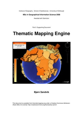
  • 1. Institute of Geography - School of GeoSciences - University of Edinburgh MSc in Geographical Information Science 2008 Awarded with Distinction Part 2: Supporting Document Thematic Mapping Engine Bjørn Sandvik This document is available from thematicmapping.org under a Creative Commons Attribution- Share Alike 3.0 License: http://creativecommons.org/licenses/by-sa/3.0/
  • 2. Thematic Mapping Engine Bjørn Sandvik Table of contents 1. Introduction 5 2. The Thematic Mapping Engine 7 2.1 Requirements .......................................................................................................7 2.3 The TME web Interface .......................................................................................8 2.3.1 User guide .....................................................................................................9 2.3.2 How the web interface works .....................................................................10 2.4 TME Application Programming Interface (API)...............................................13 2.4.1 TME DataConnector class ..........................................................................14 2.4.2 TME ThematicMap class............................................................................15 3. Data preparation 17 3.1 Using open data..................................................................................................17 3.2 UN statistics .......................................................................................................17 3.3 World borders dataset ........................................................................................18 3.4 International country codes................................................................................20 4. Database 21 4.1 Uploading spatial data........................................................................................21 4.2 Uploading statistical data...................................................................................22 4.3 Querying and transforming spatial data.............................................................23 5. Thematic mapping techniques for KML 26 5.1 The KML styling mechanism ............................................................................26 5.2 Mathematical scaling of point symbols .............................................................26 5.3 Proportional symbols .........................................................................................28 5.3.1 Proportional image icons ............................................................................28 5.3.2 Drawing regular polygons...........................................................................29 5.3.3 Proportional 3-D Collada objects................................................................31 5.4 Chart maps .........................................................................................................34 5.5 Bar maps ............................................................................................................35 5.6 Choropleth maps ................................................................................................36 5.7 Prism maps.........................................................................................................37 5.8 Temporal maps...................................................................................................38 5.9 Map tiles.............................................................................................................39 5.9.1 GDAL2Tiles ...............................................................................................39 5.9.2 KML super-overlay.....................................................................................40 5.10 Map colours .....................................................................................................41 5.11 Map legend.......................................................................................................42 5.11.1 Creating colour legends with GD .............................................................43 5.12 File compression ..............................................................................................44 6. The thematic mapping website 45 7. References 48 2
  • 3. Thematic Mapping Engine Bjørn Sandvik List of figures Figure 1: The interfaces of the Thematic Mapping Engine. ..........................................7 Figure 2: The web interface of the Thematic Mapping Engine .....................................8 Figure 3: Prism map shown with the Google Earth Plug-in. .......................................10 Figure 4: The plug-in is currently not supporting the KML time primitives...............10 Figure 5: AJAX based communication between web browser and web server...........11 Figure 6: TME web server infrastructure.....................................................................12 Figure 7: TME Application Programming Interface (API) .........................................13 Figure 8: Choropleth map in Google Earth..................................................................14 Figure 9: Choropleth map in Google Maps. ................................................................14 Figure 11: The world borders Shapefile ......................................................................18 Figure 12: World borders Shapefile: The resolution of the original dataset................19 Figure 13: World borders Shapefile: After removing island polygons........................19 Figure 14: World borders Shapefile: After simplifying borders..................................19 Figure 15: Entity-Relationship (ER) diagram showing the database structure............21 Figure 16: KML winding order....................................................................................24 Figure 17: Comparsion of 2-D and 3-D symbols.........................................................27 Figure 18: GDP per capita with 1-D bars, 2-D circles and 3-D spheres......................27 Figure 19: The KML icon images used to make proportional symbols ......................28 Figure 20: Proportional symbol map in Google Earth.................................................29 Figure 21: Proportional symbol map in Microsoft Virtual Earth. ...............................29 Figure 22: Scaling error in Google Earth.....................................................................29 Figure 23: Various regular polygons ...........................................................................30 Figure 24: Regular polygons in Google Maps. ............................................................31 Figure 25: Regular polygons in Google Earth. ............................................................31 Figure 26: How an object should be positioned in Google SketchUp.........................32 Figure 27: The Tape Measure Tool in Google SketchUp............................................32 Figure 28: The Paint Bucket tool in Google SketchUp ...............................................32 Figure 29: Collada objects available in the Thematic Mapping Engine......................33 Figure 30: Population in Southeast Asia visualised with 3-D domes..........................33 Figure 31: Population in Southeast Asia visualised with 3-D humans........................33 Figure 32: Pie chart showing age distribution. ............................................................34 Figure 33: World population visualised with scaled pie charts in Goole Earth...........34 Figure 34: World population visualised with scaled pie charts in Goole Maps ..........34 Figure 35: Bar map in Google Earth............................................................................35 Figure 36: Bar map in Google Earth (variable diameter) ............................................35 Figure 37: The polygon hole problem .........................................................................37 Figure 38: The Google Earth time animation. .............................................................39 Figure 40: Map tiles in Google Earth ..........................................................................40 Figure 41: The RGB colour cube.................................................................................41 Figure 42: Choropleh map showing life expectancy by using equal intervals ............43 Figure 43: Choropleh map showing life expectancy by using qunatiles .....................43 Figure 44: Colour legend generated by the GD library ...............................................43 Figure 46: Number of visitors to thematicmapping.org website .................................47 3
  • 4. Thematic Mapping Engine Bjørn Sandvik List of tables Table 1: Elements of TME web interface ......................................................................9 Table 2: UNdata indicators ..........................................................................................18 Table 3: KML style elements.......................................................................................26 Table 4: Number of map tiles for increasing zoom levels ...........................................39 Table 5: Number of visits to thematicmapping.org .....................................................47 4
  • 5. Thematic Mapping Engine Bjørn Sandvik 1. Introduction The aim of this research is to determine whether Keyhole Markup Language (KML) can be used for thematic mapping. As a proof-of-concept, the work culminates in the implementation of a fully functioning open source application, the Thematic Mapping Engine1. The term neogeography is commonly applied to the set of technologies and techniques presented in this document. Neogeography combines the complex techniques of cartography and GIS and places them within the reach of users and developers (Turner, 2006; Walsh, 2008; Davis, 2007). “Every now and again a web based service comes along that takes our breath away, Bjørn Sandvik's Thematic Mapping Engine is one of those services. (…) His Thematic Mapping Engine enables you to visualise global statistics on Google Earth in a way that only a few years ago would have been a showstopper using high end tools such as ESRI's ArcGlobe.” Dr Andrew Hudson-Smith, Digital Urban 1 July 20082 The Thematic Mapping Engine was developed using open source software, and it is released as an open source project. The goal was to develop a low-cost solution suitable for non-profits and public benefit organisations. The application also demonstrates what it is possible to achieve using open source tools, open standards and datasets in the public domain. Cartography and GIS have both emerged as major capabilities on the web. Distributed maps are different from traditional static maps in that they link information from various sources and provide a user-defined environment (Crampton, 2001). “Mapping should proceed thorough multiple, competing visualisations which are not created by a cartographer and transmitted to the user but made on the spot by the user acting as his or her own cartographer.” Jeremy W. Crampton (2001:236) Such mapping environments are now easier to create with recent advances in web technologies and standards. The user can, to a large extent, determine what information is to be displayed and in what context. This project aimed to provide data, visualisation tools and a cartographic toolbox to the user in a web-based interface. A step-wise approach was chosen in order to meet this aim: 1. Data preparation The first step involved finding appropriate statistical and spatial data that could be combined and used for thematic mapping. The data had to be gathered from various sources and stored in a database. 1 http://thematicmapping.org/engine 2 http://digitalurban.blogspot.com/2008/07/google-earth-thematic-mapping-engine.html 5
  • 6. Thematic Mapping Engine Bjørn Sandvik 2. Thematic mapping with KML A scripting language (PHP) was used to query the database and transform the result into KML documents representing various thematic mapping techniques. 3. Thematic Mapping Engine The Thematic Mapping Engine was developed to demonstrate how these techniques could be utilised in a web application. 4. Evaluation The various techniques were evaluated after gaining feedback from people using the Thematic Mapping Engine. The methods of thematic mapping are well described in the cartographic literature, but it was hard to find books and journal articles describing the use of KML and geobrowsers for this purpose. There is a lot of development going on, but little has so far been described in the academic literature. The focus was therefore shifted towards the “blogosphere”3. Blogs are now widely used among “geeks” and professionals alike, to present their own work and perspectives and to comment on other people’s work. Bloggers actively review and comment on the latest trends and developments, and this turned out to be a valuable information source for this project. A dedicated website4 was established to present the various thematic mapping techniques to a wider audience. This website became popular in the blogosphere, and it was also featured by the United Nations and Google. A lot of valuable feedback was received as a result of this publicity. This document is divided into five sections. The Thematic Mapping Engine is described in the first section. The second and third section describes how spatial and statistical data were collected, optimised, stored and retrieved. The forth section describes in detail the thematic mapping techniques introduced in the Research Paper (Sandvik, 2008), using code samples from the Thematic Mapping Engine. The last section shows how the thematicmapping.org website was used to exchange ideas with a wider community. 3 Blogosphere is a collective term encompassing blogs and their interconnections. 4 http://thematicmapping.org 6
  • 7. Thematic Mapping Engine Bjørn Sandvik 2. The Thematic Mapping Engine The Research Paper explains how Keyhole Markup Language (KML) and geobrowsers can be used for thematic mapping (Sandvik, 2008). The experiments show that KML has a great potential for thematic mapping, even though the techniques are complicated to use for non-programmers. By embedding the techniques in a Thematic Mapping Engine, it was possible to hide this complexity. TME allows the user to create thematic maps through an easy to use web interface, or by writing a few lines of code. Thematic KML/KMZ Mapping Engine Thematic Mapping Parameters Web PHP API Interface Figure 1: The interfaces of the Thematic Mapping Engine. Figure 1 shows how the Thematic Mapping Engine works on a high level. The engine takes statistical data (attributes), spatial features and thematic mapping parameters as input and returns a KML/KMZ file. This file can be viewed in Google Earth, or other geobrowsers supporting the KML standard. TME can be accessed from a web interface (section 2.3) or from a PHP script (section 2.4). 2.1 Requirements The Thematic Mapping Engine requires the following software (all are open source and available free of charge): • PHP (Version 5) PHP is a computer scripting language originally designed for producing dynamic web pages5. • MySQL (Version 5) MySQL is a relational database management system (RDBMS), especially popular for web applications6. 5 http://www.php.net 6 http://www.mysql.com 7
  • 8. Thematic Mapping Engine Bjørn Sandvik • Apache HTTP Server The Apache HTTP Server is an open source web server, developed and maintained by the Apache Software Foundation7. Both Linux and the Windows operating systems can be used. This software combination is often referred to as the LAMP8 or WAMP9 stack. This software combination is popular because of its low acquisition costs and because of the ubiquity of its components. It is the standard software package installed on many web servers (Kay, 2006). The easiest option is to use a hosting provider whereby this software is pre-installed on the web server. The Thematic Mapping Engine was successfully installed using a web hosting solution from Bluehost10. The software stack can also be installed on a PC by using the XAMPP11 distribution. XAMPP is an easy to install Apache distribution containing MySQL, PHP and Perl. Only the XAMPP Windows distribution has been tested. The TME web interface requires the Ext JS JavaScript library. To be able to preview thematic maps in the web browser, the Google Earth Plug-in is required. These components can be installed from the following web sites: • Ext JS (Version 2.1): http://extjs.com/products/extjs • Google Earth Plug-in: http://code.google.com/apis/earth 2.3 The TME web Interface With the TME web interface, thematic maps can be created in a web browser, without a single line of code. This is achieved through an interactive web form where the user can select between statistical indicators and various thematic mapping techniques. Mapping parameters, like the colour and size, can be readily changed. The form returns a KMZ file which can be visualised directly in the web browser using the new Google Earth plug-in, or downloaded to a computer. The web interface supports all major web browsers, including Internet Explorer 6+, Firefox 1.5+, Safari 3+ and Opera 9+. The Google Earth plug-in currently only supports Figure 2: The web interface of the web browsers on the Windows operating Thematic Mapping Engine system. 7 http://www.apache.org 8 LAMP is an acronym for Linux, Apache, MySQL and PHP. 9 WAMP is an acronym for Windows, Apache, MySQL and PHP. 10 http://www.bluehost.com 11 http://www.apachefriends.org/en/xampp.html 8
  • 9. Thematic Mapping Engine Bjørn Sandvik 2.3.1 User guide This guide explains how to use the web interface to create a thematic map. Table 1: Elements of TME web interface Select the statistical indicator and one of the years available. Select one of the thematic mapping techniques (Choropleth, Prism, Bar, Proportional symbol) Prism map: Maximum height (in metres) of the prisms can be changed. Bar map: Maximum height (in metres) and bar radius can be changed. Proportional symbol: Select symbol type (Image, Regular polygon or 3-D object) and symbol shape. Maximum size can be changed. Choose colour scale or single colour map. The colour scale can be unclassed or classed (equal intervals or quantiles). The number of classes can be changed (2-9 classes). Select Time series or Time slider to visualise statistics for all available years. Select information elements that should be displayed on the map. The default title, description and source of the map can be changed. Click the Preview button to view map in the web browser (requires Google Earth plug-in) or the Download button to download the KMZ file. 9
  • 10. Thematic Mapping Engine Bjørn Sandvik 2.3.2 How the web interface works The TME web interface can be characterised as a Rich Internet Application (RIA), a web application that has the features and functionality of traditional desktop applications (Loosley, 2006). In a traditional web application, all processing is done on the web server and a new web page is downloaded each time the user clicks. RIAs transfer the processing necessary for the user interface to the web browser, but keep the bulk of the data back on the web server. The web interface was developed using HTML, JavaScript, Ext JS, Google Earth API and AJAX12 techniques. By combining these technologies, it was possible to create a responsive user experience. Ext JS is a cross-browser JavaScript library for building desktop-like web applications. Ext is dual licensed under the General Public License (GPL), which TME uses, and a commercial license. By using Ext JS, it was possible to build interactive form elements which responded to various events initialised by the user or the program flow. The validity check of the user inputs is performed in the web browser and not on the server. Ext JS also controls the AJAX based communication between the web browser and the web server. Figure 3: Prism map shown with the Google Earth Plug-in. AJAX is a group of interrelated web development techniques used for creating interactive web applications. By using AJAX, it is possible to retrieve data from the web server asynchronously in the background without interfering with the display and behaviour of the existing web page. Despite its name, XML is not required as the data-interchange format. TME uses the JSON13 encoding to transfer data from the web server to the web browser, as it is more readily generated and parsed by programming languages. In May 2008, Google launched the Google Figure 4: The plug-in is currently not Earth Plug-in together with a free supporting the KML time primitives. All JavaScript API (Rademacher, 2008). This prisms are rendered on top of each other, regardless of the time specified. made it possible to embed Google Earth in a web interface, instead of having to switch between two applications (the web browser and Google Earth). 12 AJAX is an acronym for Asynchronous JavaScript and XML. 13 JSON is an acronym for JavaScript Object Notation. 10
  • 11. Thematic Mapping Engine Bjørn Sandvik Web browser 1. Get list of indicators Web server Google Earth API PHP 2. Get list of available years Ext JS MySQL 3. Make KML/KMZ document HTML / JavaScript Apache 4. Download KML/KMZ file Figure 5: AJAX based communication between web browser and web server. Figure 5 shows the communication occurring between the web browser and the web server when the user is creating a thematic map: 1. When the web interface is loaded by the web browser, an AJAX request is automatically fired to the web browser14. The browser is asking for a list of all available statistical indicators, and this list is returned by the web server. This information is added to the first drop-down box in the web form. 2. When the user selects one of the indicators in the list, a new request is sent, asking for a list of years where data is provided. The years are added to the second drop-down box. 3. The third request is sent when the user clicks the Preview or Download button. All of the map parameters, representing the choices made by the user, are then transferred to the web server. The parameters are used to generate a KML document, which are zipped into a KMZ file and stored on the server. A reference (URL) to the KMZ file is returned to the browser. 4. If the Preview button was clicked, the KMZ file is automatically loaded by the Google Earth Plug-in. If the Download button was clicked, a link to a KMZ file is displayed. The user can download the file by clicking on this link. 14 This happens to be the same web browser as the web interface was loaded from, but it could also be a different web server. 11
  • 12. Thematic Mapping Engine Bjørn Sandvik Web browser Web server MySQL Form Data Connector Handler MySQL Database File Server Thematic Mapping Engine KML/KMZ files Figure 6: TME web server infrastructure Figure 6 shows how the requests from the web browser are handled by the web server. All communication goes through a single PHP script. This Form Handler script makes use of two additional PHP classes: • MySQL Data Connector class This class retrieves data from the MySQL database (indicators, years or data used to make a thematic map). This class is further explained in section 2.4.1. • Thematic Mapping class The data from the MySQL Data Connector class are passed on to this class, together with the map parameters sent from the web browser. This information is used to generate the KML document. This class is further explained in section 2.4.2. 12
  • 13. Thematic Mapping Engine Bjørn Sandvik 2.4 TME Application Programming Interface (API) The Thematic Mapping Engine can also be used as an application programming interface (API). This allows thematic maps to be created with a few lines of PHP code. Existing or new applications can use this API to add thematic mapping functionality. Web server MySQL PHP Data Connector Application MySQL Database File Server Thematic Mapping Engine KML/KMZ files Figure 7: TME Application Programming Interface (API). The Form Handler script is here replaced by a custom PHP script. The TME API works by including the two classes introduced above in a PHP application. This is the code required to create a choropleth map: 01 include ('TME_MySQL_DataConnector.php'); 02 include ('TME_Engine.php'); 03 04 $dataConnector = new DataConnector(); 05 $dataStore = $dataConnector->getDataStore(68, 2005, 0); Create a new data connector objects, and use this object to retrieve a multidimensional 06 array.$parameters = array( 'mapType' 07 => 'choropleth', 08 'indicator' => 68, 09 'year' => 2005, 10 'classification' => 'equal' ); 11 12 $map = new ThematicMap($dataStore, $parameters); Build$file = of mapping parameters. 13 an array $map->getKML(); The two classes are included in line 1 and 2. A new dataConnector object is created from the DataConnector class (line 4). The getDataStore method is called to retrieve the data required to create a thematic map (line 5). The parameters refer to the indicator id, year and a region code. The region code is used only to select the values and features from one continental region (e.g. Africa)15. All map parameters are added 15 Region codes are from United Nations Statistical Division: http://unstats.un.org/unsd/methods/m49/m49regin.htm 13
  • 14. Thematic Mapping Engine Bjørn Sandvik to an array16 (line 7-10). A new map object is created from the ThematicMap class by adding the data array and the map parameters (line 12). Finally, a reference (URL) to the KMZ file is retrieved by calling the getKML method of the map object. Figure 8: The KMZ file, returned from the PHP Figure 9: The same KMZ file displayed in script above, displayed in Google Earth. Google Maps. All valid map parameters are listed in appendix C1. An additional example for proportional symbol maps is included in appendix C2. 2.4.1 TME DataConnector class The object-oriented programming (OOP) features introduced in PHP 5 were used to create an application that could be readily extended (Ullman, 2007). All queries to the MySQL database are kept in a separate class (TME_MySQL_DataConnector.php). A different database can be used by adding a new PHP data connector class17. The DataConnector class contains three methods: • getIndicators () This method returns a list of the statistical indicators in the database. • getIndicatorYears ($indicatorID) This method returns a list of available years for one indicator. • getDataStore ($indicatorID, $year, $region) This method retrieves the spatial features and statistical values required to create a thematic map. The data is returned in a multidimensional array: 16 A data structure that associates values with keys is also called a hash table. 17 Instead of creating a class interacting with a MySQL database, one could make one that interacts with a non-specific database. By using the OOP principles of inheritance and overriding, a more particular class for MySQL could be defined. This approach would enforce new data classes to implement the same functionality as the general class. 14
  • 15. Thematic Mapping Engine Bjørn Sandvik dataStore => Array [features] => Array [feature id] => Array [name] => name [lon] => longitude [lat] => latitude [wkt] => WKT geometry [...] [indicators] [indicator id] [name] [description] [source] [decimals] [max] [min] [values] => Array [2005] => Array [feature id] => value [...] [...] [years] => Array [...] The spatial features (e.g. countries) and the statistical values are kept separately in the array, as not all features have values, and not all values have associated features. Name, longitude, latitude and geometry (i.e. border) is added for each feature. Various metadata are added, together with the statistical values. 2.4.2 TME ThematicMap class The multidimensional array retrieved from the DataConnector class is passed on to the ThematicMap class together with the mapping parameters. Figure 10 shows a flow chart of how the KML document is created when the getKML method is called. Firstly, the shared styles are defined. The shared styles will be different for each thematic mapping technique. An exception is choropleth and prism maps, which have the same shared styles. There are two for-each loops. The outermost loop runs through each of the years. A new KML Folder element is added for each year. The inner loop runs throughout all the features (e.g. countries) present in the data store. A KML Placemark element is added for each feature. Within this element, feature specific styles and the feature itself are added. How this is done for each thematic mapping technique is explained in section 5. This is a simplified view, as there are many more conditions for handling all the map parameters. 15
  • 16. Thematic Mapping Engine Bjørn Sandvik Add KML <kml> header Symbol (5.3) Technique Type Choropleth Bar Image Polygon Collada Prism (5.6) (5.5) (5.3.1) (5.3.2) (5.3.3) Add Add Add Add Colourise shared shared shared shared Collada style style style style object(s) <Folder> For each year <Placemark> For each feature Symbol (5.3) Technique Type Choropleth Prism Bar Image Polygon Collada (5.6) (5.7) (5.5) (5.3.1) (5.3.2) (5.3.3) Add style Add style Add style Add style Add style Add link to and and and and and Collada feature feature feature feature feature object </Folder> Figure 10: Flow chart </Placemark> showing how a KML document is created. The numbers refer to the sections in which Add map title and each technique is legend </kml> described. 16
  • 17. Thematic Mapping Engine Bjørn Sandvik 3. Data preparation Due to special interest and availability, international statistics were used for the thematic mapping experiments. Three types of data were gathered: a spatial dataset containing world borders, statistical data from the United Nations, and international country codes. The latter was used to link statistical values to the spatial features. Although this is principally global data, the techniques developed here are scale- independent. 3.1 Using open data Since KML is an open, human-readable format, it was required to use data provided under open and non-restrictive licensing terms. The following requirements had to be met: • Access for all. Anyone with an internet connection should be able to access the mapping examples. The terms of use of the Google mapping technology also states that “your service must be freely accessible to end users”18. • Using vector data. Many data licenses do not readily permit use in an open interface as data providers are concerned about backward engineering. Using an open standard like KML would violate such licensing terms. • Allow redistribution. Many data providers forbid redistribution of their data, which is basically what this project is doing by using KML and publicly available geobrowsers. An important goal of this project was also to show the benefits of using public domain (“open”) data. 3.2 UN statistics UNdata19 is a new internet-based data service which offers free access to a wide range of global statistics through a single entry point. The database service is offered by the United Nations Statistics Division (UNSD). UNdata enables users to access a large number of UN databases, either by browsing the data series, or through a keyword search. The non-restrictive licensing terms made this data service an ideal source for this project. The following statistical indicators were downloaded from UNdata in an XML format: 18 http://code.google.com/apis/maps/terms.html 19 http://data.un.org 17
  • 18. Thematic Mapping Engine Bjørn Sandvik Table 2: UNdata indicators Indicator Years AIDS estimated deaths, aged 0-49 2001 - 2005 Children under five mortality rate 1960 - 2005 CO2 emissions 1980 - 2004 CO2 emissions per capita 1980 - 2004 GDP per capita 1975 - 2006 Infant mortality rate (0-1 year) 1960 - 2005 Internet users 1990 - 2005 Internet users per 100 population 1990 - 2005 Life expectancy at birth (both sexes) 1950 - 2045 Life expectancy (females) 1950 - 2045 Life expectancy (males) 1950 - 2045 Mobile phone subscribers 1980 - 2004 Mobile phone subscribers per 100 inhabitants 1980 - 2006 Patent applications 1984 - 2002 Percentage aged 0-14 1950 - 2050 Percentage aged 15-59 1950 - 2050 Percentage aged 60 or over 1950 - 2050 Population 1950 - 2050 Tuberculosis death rate 1990 - 2005 The table shows the long time series for some of the indicators - up to 100 years, including projections. The XML format did not include metadata like indicator name and description, and this information had to be copied manually. 3.3 World borders dataset A world borders dataset was needed for choropleth mapping and to calculate the positions (centroids) of the proportional symbols. Ideally, border data and country statistics should be from the same source, to ensure that the areas are identical. The United Nations International Boundaries Project20 offers a 1:1 and 1:15 million-scale dataset, which reflects the cartography practice of the UN Cartographic Section. Unfortunately, this dataset is only accessible to the UN community, due to sensitivity linked to international boundaries. A world borders Shapefile meeting the above requirements was downloaded from the Mapping Hacks website21. This dataset was originally derived by Schyler Erle from public domain sources. Various changes were made to Figure 11: The world borders Shapefile displayed with an make the dataset more suitable Equirectangular (Plate Carrée) projection. for thematic mapping (all changes are listed in appendix A): 20 http://boundaries.ungiwg.org 21 http://mappinghacks.com/data 18
  • 19. Thematic Mapping Engine Bjørn Sandvik • Added geographic coordinate system: GCS_WGS_198422 • Polygons representing one country/area were merged into one feature. • Various feature changes to make the dataset more compatible with the ISO 3611-1 country codes used by the United Nations. • Region and sub-region codes from the UN Statistical Division were added. • Longitude/latitude values for each country were added. Generalisation is the process of reducing the information content of maps due to scale change, map purpose, intended audience, and/or technical constraints (Slocum et al. 2005). When doing thematic mapping on the web, it is important to limit the amount of data transferred between the server and the mapping client. In addition, modern web browsers are only capable of displaying low-resolution vector data. The original world borders dataset Figure 12: The resolution of the original dataset. consisted of 3775 polygons. By deleting “small” island polygons, this number was reduced to 463. This was done manually to avoid the deletion of valid island states. Figure 12 and 13 show the effect on the Caribbean. All countries in the region are still represented. The remaining polygons were simplified using the Simplify Polygon tool in the ArcToolbox. The polygon simplification algorithm (POINT_REMOVE) keeps the so-called critical points that depict the Figure 13: After removing island polygons. essential shape of the polygon and removes all other points. The tolerance, that determines the degree of simplification, was set to 0.3 decimals degrees. Figure 14 shows the effect of the simplification algorithm. Even though the borders are greatly simplified, the main country shapes are preserved. To be able to generate proportional symbol maps, a latitude/longitude position was needed for each country. GeoDa23 was used to compute the centroids of each country. Figure 14: After simplifying borders. The positions had to be manually adjusted 22 The reference system used by KML is based on geographic coordinates (latitude and longitude) in WGS84 (World Geodetic System, 1984). This is the only reference system currently supported by KML (Wilson, 2008). 23 https://www.geoda.uiuc.edu 19
  • 20. Thematic Mapping Engine Bjørn Sandvik due to the uneven shape of many countries. The longitude/latitude values were added by inserting two extra columns in the attribute table. Appendix A lists all of the attribute columns in the world borders Shapefile. 3.4 International country codes A common identifier was needed to be able to link the statistical values to spatial features. The original world borders dataset contained FIPS codes, while UNdata uses ISO 3166-1. Codes for the Representation of Countries (ISO 3166-1)24 is maintained by the International Organisation for Standardisation (ISO). The standard includes two- and three-character alphabetic codes (alpha-2 and alpha-3) and three-digit numerical codes (numeric-3). Countries, Dependencies, Areas of Special Sovereignty, and Their Principal Administrative Divisions (FIPS 10)25 is maintained by the United States National Geospatial-Intelligence Agency, and intended for general use throughout the US Government. The country codes were downloaded from the World Factbook26 and checked against the listing from UN Statistical Division27. All ISO 3166-1 country codes (alpha-2, alpha-3 and numeric-3) and the FIPS codes (when applicable) were added to the attribute table of the world borders Shapefile. Only ISO 3166-1 numeric-3 was used for this project, but the other codes make it easier to link in other data sources if this project were to be extended. 24 http://www.iso.org/iso/country_codes.htm 25 http://www.itl.nist.gov/fipspubs/fip10-4.htm 26 https://www.cia.gov/library/publications/the-world-factbook/appendix/appendix-d.html 27 http://unstats.un.org/unsd/methods/m49/m49alpha.htm 20
  • 21. Thematic Mapping Engine Bjørn Sandvik 4. Database The world borders dataset and statistics from UNdata were stored in a MySQL28 database. MySQL was chosen more because of its availability than its spatial capabilities. MySQL has limited support for spatial data, but it was sufficient for this project. An alternative would be to use the PostgreSQL29 database with the PostGIS30 spatial extension, but this would exclude many potential users since PostGIS is seldom pre-installed by hosting providers. Geometry M 1 Spatial ref. Indicator columns system 1 M Indicator M 1 Country values (spatial) Figure 15: Entity-Relationship (ER) diagram showing the database structure. All table columns are listed in appendix B. Figure 15 shows an Entity-Relationship (ER) diagram of the database structure. One indicator can have several indicator values, and one country (feature) can have several indicator values. All indicator values are therefore kept in a separate table, with indicator id and country id as foreign keys. 4.1 Uploading spatial data The GDAL/OGR library31 was used to upload the world borders Shapefile to the MySQL database. This library contains the ogr2ogr utility program which converts simple features data between various file and database formats. The following command was used to upload the features (including the attribute table): ogr2ogr –f MySQL MySQL:myDatabase, user=root,password=myPassword TM_WORLD_BORDERS_SIMPL-0.1.shp –nln Country –nlt MULTIPOLYGON – update –overwrite –lco GEOMETRY_NAME=geom The country borders were stored in the database using the MultiPolygon datatype (MySQL, 2008). This datatype was needed because many countries consist of several polygons (i.e. land areas/islands). Some of the polygons are complex (i.e. contains 28 http://www.mysql.com 29 http://www.postgresql.org 30 http://postgis.refractions.net 31 Geospatial Data Abstraction Library (GDAL/OGR) is a cross platform translator library for raster and vector geospatial data formats that is released under an X/MIT style open source license by the Open Source Geospatial Foundation (OSGeo). http://www.gdal.org 21
  • 22. Thematic Mapping Engine Bjørn Sandvik holes) because of enclaves. The longitude/latitude position for each country was stored in two table columns. An alternative would be to use a spatial datatype (GEOMETRY POINT). The above command also created two extra tables (geometry_columns and spatial_ref_system). These tables are required according to the OpenGIS Simple Features Implementation Specification for SQL (OGC, 1999; Butler, 2006). 4.2 Uploading statistical data The statistical indicators were downloaded from UNdata in an XML format, and uploaded to the MySQL database through a tailored PHP script: // Check if file exists if (file_exists($file)) { // Load XML file $xml = simplexml_load_file($file); // Loop through all records foreach ($xml->data->record as $record) { // Loop through all fields in a record foreach ($record->field as $field) { // Store field values switch ($field['name']) { case 'Variable Code': case 'Series Code': $indicator = (int)$field; break; case 'Country or Area Code': $country = (int)$field; break; case 'Year': case 'Year(s)': $year = (int)$field; break; case 'Value': $value = (float)$field; break; } } // Add record to database table $sql = "INSERT INTO indicator_values (indicator, country, year, value) VALUES ($indicator, $country, $year, $value);"; if (@mysqli_query($dbc, $sql) === TRUE) { printf("Query: $sqln"); } } } else { exit("Failed to open $file."); } The script above reads and parses an XML file. Since it was impossible to download indicator metadata from UNdata, this information had to be entered manually in phpMyAdmin32. 32 http://www.phpmyadmin.net 22
  • 23. Thematic Mapping Engine Bjørn Sandvik 4.3 Querying and transforming spatial data MySQL stores spatial data in an internal geometry format (MySQL, 2008). The data can only be retrieved in this internal format or as Well-Known Text (WKT) or Well- Known Binary (WKB) representations (OGC, 1999). WKT/WKB predates the Geographical Markup Language (GML), which is now a more commonly used format. By using the AsText function, MySQL retrieves geometry in WKT format. This SQL query returns the simplified border of Italy: SELECT AsText(geom) FROM `country_simpl` WHERE un=380 Result: MULTIPOLYGON(((15.528889 38.13694,15.081388 36.649162,12.422222 37.796104,13.316666 38.21833,15.528889 38.13694)),((9.513332 41.14666,9.5691660000002 39.150551,8.406944 38.958611,8.192499 40.913605,9.513332 41.14666)),((12.127777 47.001663,13.718655 46.526611,13.383055 46.297218,13.716944 45.596107,12.281387 45.468048,12.368332 44.246666,13.621666 43.553886,14.739721 42.085548,16.141941 41.914162,15.932499 41.47805,18.512218 40.136665,18.349442 39.791939,16.913609 40.445549,16.486664 39.767494,17.169167 38.963333,16.062496 37.924164,15.631666 38.011665,16.2225 38.910828,15.666666 40.03083,11.098888 42.393051,10.107498 44.0075,8.7488880000001 44.429161,7.528055 43.788605,7.662222 44.17083,6.9763880000001 44.284164,6.61976 45.110138,7.1277770000001 45.257774,7.038054 45.931938,7.855742 45.919052,8.4363880000001 46.463333,9.036665 45.837776,9.2819440000001 46.495827,10.129999 46.227219,10.471235 46.871353,12.127777 47.001663),(12.459166 43.896111,12.509998 43.986938,12.415798 43.957954,12.459166 43.896111),(12.445090330889 41.903117521785,12.456660170954 41.901426024699,12.451653339581 41.907989033391,12.445090330889 41.903117521785))) Since the WKT and KML formats are very different, it was not straightforward to achieve a conversion of complex polygons. This function was made for the conversion: public function wkt2kml($wkt) { // Change coordinate format $wkt = preg_replace( "/([0-9.-]+) ([0-9.-]+),*/e", "round('$1',2).','.round('$2',2).',0 '", $wkt ); $wkt = substr($wkt, 15); // Remove 'MULTIPOLYGON(((' $wkt = substr($wkt, 0, -3); // Remove ')))' $polygons = explode(')),((', $wkt); // Find all polygons $kml = '<MultiGeometry>; foreach ($polygons as $polygon) { $kml .= '<Polygon>'; $boundary = explode('),(', $polygon); // Find all polygon boundaries $kml .= '<outerBoundaryIs>' . '<LinearRing>' . '<coordinates>' . self::kmlReverseCoordinates($boundary[0]) . '</coordinates>' 23
  • 24. Thematic Mapping Engine Bjørn Sandvik . '</coordinates>' . '</LinearRing>' . '</outerBoundaryIs>'; for ($i=1; $i < count($boundary); $i++) { // If inner boundaries $kml .= '<innerBoundaryIs>' . '<LinearRing>' . '<coordinates>' . self::kmlReverseCoordinates($boundary[$i]) . '</coordinates>' . '</LinearRing>' . '</innerBoundaryIs>'; } $kml .= '</Polygon>'; } $kml .= '</MultiGeometry>'; return $kml; } } } The coordinates returned from the MySQL database had 6 or more decimal points. This is far more than needed, and does not reflect the precision of the simplified borders. The function above reduces the number of decimal points to 2. When the KML polygons were used to create a 3-D prism map (see section 5.7), the prisms were not shaded properly (figure 16). The reason for this turned out to be the clockwise orientation of the polygon vertices (winding order). 3-D implementations of KML use the vertex winding order to determine the direction in which it faces33. This is necessary to display the correct lighting on curved surfaces. For the prisms to be displayed properly, the vertex order had to be anti-clockwise. Figure 16: The left image shows a prism map rendered in Google Earth, where the polygon vertices are in a clockwise order. In the right-hand image, the vertex order is counter-clockwise, and the polygons are properly shaded. 33 http://bbs.keyhole.com/ubb/showflat.php/Cat/0/Number/166922 24
  • 25. Thematic Mapping Engine Bjørn Sandvik The vertex order was corrected by adding this PHP function: function kmlReverseCoordinates($coordinates) { $coordinates = explode(" ", $coordinates); $coordinates = array_reverse($coordinates); $coordinates = implode(" ", $coordinates); return $coordinates; } The above wkt2kml function returns this KML structure representing the Italian border: <MultiGeometry> KML <Polygon> <outerBoundaryIs> <LinearRing> <coordinates> 15.53,38.14,0 13.32,38.22,0 12.42,37.8,0 15.08,36.65,0 15.53,38.14,0 </coordinates> </LinearRing> </outerBoundaryIs> </Polygon> <Polygon> <outerBoundaryIs> <LinearRing> <coordinates> 9.51,41.15,0 8.19,40.91,0 8.41,38.96,0 9.57,39.15,0 9.51,41.15,0 </coordinates> </LinearRing> </outerBoundaryIs> </Polygon> <Polygon> <outerBoundaryIs> <LinearRing> <coordinates> 12.13,47,0 10.47,46.87,0 10.13,46.23,0 9.28,46.5,0 9.04,45.84,0 8.44,46.46,0 7.86,45.92,0 7.04,45.93,0 7.13,45.26,0 6.62,45.11,0 6.98,44.28,0 7.66,44.17,0 7.53,43.79,0 8.75,44.43,0 10.11,44.01,0 11.1,42.39,0 15.67,40.03,0 16.22,38.91,0 15.63,38.01,0 16.06,37.92,0 17.17,38.96,0 16.49,39.77,0 16.91,40.45,0 18.35,39.79,0 18.51,40.14,0 15.93,41.48,0 16.14,41.91,0 14.74,42.09,0 13.62,43.55,0 12.37,44.25,0 12.28,45.47,0 13.72,45.6,0 13.38,46.3,0 13.72,46.53,0 12.13,47,0 </coordinates> </LinearRing> </outerBoundaryIs> <innerBoundaryIs> <LinearRing> <coordinates> 12.46,43.9,0 12.42,43.96,0 12.51,43.99,0 12.46,43.9,0 </coordinates> </LinearRing> </innerBoundaryIs> <innerBoundaryIs> <LinearRing> <coordinates> 12.45,41.9,0 12.45,41.91,0 12.46,41.9,0 12.45,41.9,0 </coordinates> </LinearRing> </innerBoundaryIs> </Polygon> </MultiGeometry> This method of representing geometry is based on GML 2.1.2 (Lake, 2005). 25
  • 26. Thematic Mapping Engine Bjørn Sandvik 5. Thematic mapping techniques for KML This section describes how the KML standard was utilised for thematic mapping. The techniques introduced in the Research Paper are here described in detail. 5.1 The KML styling mechanism In KML, features and geometries are specified along with their styles. KML does not support more flexible mechanisms, such as Cascading Style Sheets (CSS) or OpenGIS Symbology Encoding, which separates content from style. A KML Style element can contain the substyle elements listed in table 3 (Google, 2008a): Table 3: KML style elements and the thematic mapping techniques where they are used. Style element Thematic mapping technique IconStyle Scaled image icons (5.3.1) PolyStyle Scaled regular polygons (5.3.2), choropleth (5.6) and prism (5.7) maps LineStyle Not in use (could be used for flow maps) ListStyle Temporal maps (5.8) BalloonStyle All maps LabelStyle All maps Styles can be shared (i.e. defined once and used by several features) or inline (i.e. specified inside the feature that uses them). 5.2 Mathematical scaling of point symbols Mathematical scaling sizes the point symbols in direct proportion to the data (Slocum et al., 2005). If a data value is 10 times that of another, the height, area or volume of the corresponding point symbol will be 10 times as large. Below are the formulae used for calculating the symbol sizes. These equations could not be embedded in a KML document, so the mathematical scaling had to be performed by a PHP script. 1-dimensional symbols (height) Equation symbolSize = (value / maxValue) * maxSize PHP $symbolSize = ($value / $maxValue) * $maxSize This is how the height of the bars or prisms are calculated. 2-dimensional symbols (area) Equation symbolSize = power(value / maxValue; 1/2) * maxSize PHP $symbolSize = ($value / $maxValue) * $maxSize This is how the proportional images and regular polygons (e.g. circle, square) are scaled. 2-D symbols use areas as the mean of expression and thereby a square root of the value. 26
  • 27. Thematic Mapping Engine Bjørn Sandvik 3-dimensional symbols (volume) Equation symbolSize = power(value / maxValue; 1/3) * maxSize PHP symbolSize = pow($value / $maxValue, 1/3) * $maxSize This is how the 3D Collada objects (e.g. cube, sphere) is scaled. 3-D objects use volume as the mean of expression to show the cube root of the value. It is one degree harder for the viewer to assess the relative size of 3-dimensional symbols compared to 2-dimensional ones (see figure 17), which again are harder to compare that 1-dimensional symbols. Figure 17: Comparsion of the circle and sphere radius for the same mapped parameter. Credit: Dominik Mikiewicz Figure 18: These three images show GDP per capita in 2006 (UNdata) using bars (1-D), circles (2-D) and spheres (3-D). Proportional symbols are not dependant on the size of the spatial unit associated with its attribute. A small country will have the same visual appearance as a big country if their respective attribute values are the same. People tend to underestimate the size of larger symbols, and an alternative to mathematical scaling is perceptual scaling (Slocum et al. 2005). The underestimation is here taken into account when constructing the formula. The visual appearance could also be improved by using a logarithmic scale. 27
  • 28. Thematic Mapping Engine Bjørn Sandvik 5.3 Proportional symbols This section describes in detail three different ways of making proportional symbols in KML. 5.3.1 Proportional image icons KML icons are used to visualise various point data, and custom icons can be added by referencing an image stored on the local file system or a remote web server. Two symbols, a circle and a square, were created using Adobe Photoshop Elements. A shadow effect was added to give the icons a slightly 3-D appearance. The symbols are white on a transparent background, and saved as PNG files. An image size of 200 x 200 px seems appropriate when the image is scaled proportional to an attribute value. KML icon images can be scaled and colourised by using the IconStyle element. Only one image is thereby needed to create symbols in different colours and sizes. This reduces the total file size and improves the performance. The symbol image is Figure 19: The KML icon images referenced in a shared style: used to make proportional symbols. <Style id='sharedStyle'> KML <IconStyle> <Icon> <href>files/symbol.png</href> </Icon> </IconStyle> <Style> The colour can also be specified in the shared style if only one colour is used. If the colour varies, it needs to be defined as an inline style for each feature, together with the scaling factor: <Placemark> KML <name>China</name> <Snippet>1,312,978,855 (2005)</Snippet> <styleUrl>#sharedStyle</styleUrl> <Style> <IconStyle> <color>e50066ff</color> <scale>7</scale> </IconStyle> </Style> <Point> <coordinates>106.514,33.42,0</coordinates> </Point> </Placemark> 28
  • 29. Thematic Mapping Engine Bjørn Sandvik When a KML Point element is contained by a Placemark element, the point itself determines the position of the Placemark’s image icon (Google, 2008a). This is achieved by defining the longitude, latitude and (optional) altitude within the coordinates element. The drawback of this method is that the map is, so far, only viewable in Google Earth. Other geobrowsers are unable properly to scale and colourise the icon images (see figure 21). Figure 20: Proportional symbol map in Figure 21: The same KML file shown in Microsoft Google Earth showing the relative population Virtual Earth. The image icons are not scaled or in each country of the world. colourised. When comparing the results from the Google Earth plug-in with the Google Earth desktop program, there is a noticeable difference: the icons are much bigger in the plug-in. The reason is different viewport sizes, and it can be considered as a Google Earth bug. There are two different ways of adjusting the size of the Figure 22: Proportional image icons in Google Earth. planet in Google Earth. The left- The circles on the right planet are not properly scaled. hand visualisation in figure 22 shows the earth in a zoomed out view. The circle images are scaled properly. The other way of changing the size of the planet is by adjusting the Google Earth window. The problem is that the circle images maintain their size while the planet shrinks or expands. The KML Icon element is here used in a way that was probably not intended. 5.3.2 Drawing regular polygons KML has no built-in support for regular polygons so these have to be generated by calculating the longitude/latitude location for each vertex of the polygon. A PHP function from the Google Earth Community forum34 was modified for this purpose. The modified function generates a KML polygon from a set of parameters: longitude, latitude, radius, number of vertices and (optional) altitude. This is, of 34 http://bbs.keyhole.com/ubb/showflat.php?Cat=&Board=SupportKML&Number=166379 29
  • 30. Thematic Mapping Engine Bjørn Sandvik course, a complicated way of making regular polygons. Part of the function is shown below: function kmlSymbolCalculator( $longitude, $latitude, $radius, $vertices, $altitude ) { $EARTH_RADIUS_EQUATOR = 6378140.0; $RADIAN = 180 / pi(); $long = $longitude / $RADIAN; $lat = $latitude / $RADIAN; $f = 1/298.257; $e = 0.08181922; for ( $bearing = 45; $bearing <= 405; $bearing += 360/$vertices ) { $b = $bearing / $RADIAN; $R = $EARTH_RADIUS_EQUATOR * (1 - $e * $e) / pow( (1 - $e*$e * pow(sin($lat),2)), 1.5); $psi = $distance/$R; $phi = pi()/2 - $lat; $arccos = cos($psi) * cos($phi) + sin($psi) * sin($phi) * cos($b); $latA = (pi()/2 - acos($arccos)) * $RADIAN; $arcsin = sin($b) * sin($psi) / sin($phi); $longA = ($long - asin($arcsin)) * $RADIAN; (...) } (...) return $kml; } Figure 23: Various regular polygons. n refers to the number of vertices. The polygon style (fill and outline) is specified in a shared style: <Style id='sharedStyle'> KML <PolyStyle> <fill>1</fill> <outline>1</outline> </PolyStyle> <LineStyle> <color>cc000000</color> </LineStyle> </Style> The fill colour is specified for each feature, since the regular polygons can be colourised according to a statistical value: 30
  • 31. Thematic Mapping Engine Bjørn Sandvik <Placemark> KML <name>China</name> <Snippet>1,312,978,855 (2005)</Snippet> <styleUrl>#sharedStyle</styleUrl> <Style> <PolyStyle> <color>e50066ff</color> </PolyStyle> </Style> <Polygon> <outerBoundaryIs> <LinearRing> <coordinates> 102.77,36.48,0 102.77,30.24,0 110.26,30.24,0 110.26,36.48,0 102.77,36.48,0 </coordinates> </LinearRing> </outerBoundaryIs> </Polygon> </Placemark> The Polygon element includes the coordinates of the vertices in the polygon, calculated by the kmlSymbolCalculator function above. Figure 24: Showing regular polygons in Google Maps. Figure 25: The polygons are skewed when visualised on a 3-D globe. 5.3.3 Proportional 3-D Collada objects One unique feature to KML is the ability to embed 3-D models or objects into the KML file (Turner, 2006). The 3-D objects used in this project were downloaded from 3D Warehouse35, an online repository for 3D models. The objects were edited in Google SketchUp36 to make them more suitable for thematic mapping: 1. Each object was positioned so that the green and red lines were touching the bottom of the object. These lines mark the ground when the object is rendered. The blue line marks the latitude/longitude position where the object will be placed, and should bisect the object (figure 26). 2. The objects from 3D Warehouse had various scales. The Tape Measure Tools was used to apply a similar scale to all objects (figure 27). 3. A default colour was added (figure 28). 35 http://sketchup.google.com/3dwarehouse 36 http://sketchup.google.com 31
  • 32. Thematic Mapping Engine Bjørn Sandvik Figure 26: How an object Figure 27: Use the Tape Measure Figure 28: Use the Paint Bucket should be positioned in Google Tool to change the scale of the tool to add a default colour to SketchUp. object. the object. Click on the Create Material icon to select a colour. The KML Model element specifies the location, orientation and scale of a Collada object. It is impossible to attach any styles to the Model element, which makes it harder to use the feature for thematic mapping. <Placemark> KML <name>China</name> <Snippet>1,312,978,855 (2005)</Snippet> <Model> <Link> <href>files/object.dae</href> </Link> <altitudeMode>absolute</altitudeMode> <Location> <longitude>106.514</longitude> <latitude>33.42</latitude> <altitude>0</altitude> </Location> <Scale> <x>140000</x> <y>140000</y> <z>140000</z> </Scale> </Model> </Placemark> The Link element specifies the Collada object to load. The Location element specifies the coordinates of the object’s origin in latitude, longitude and altitude. The Scale element scales the object along the x, y and z axes in the object’s coordinate space. As for bars, the z (height) dimension could represent a different statistical indicator than the x/y dimension. Collada objects can also be placed on top of each other by specifying an increasing altitude value (e.g. to create stacked bars). Since it is impossible to colourise Collada objects in KML, this needs to be done in the Collada file itself. This PHP script shows how this can be achieved: 32
  • 33. Thematic Mapping Engine Bjørn Sandvik foreach($this->classColours as $class => $classColour){ $colladaColour = self::rgb2collada($classColour); // Read collada model $filename = "files/$this->symbolShape.dae"; $handle = fopen($filename, "r"); $collada = fread($handle, filesize($filename)); fclose($handle); // Search and replace colour $pos = strpos($collada, '<effect id="material0-effect" ...>'); $pos = strpos($collada, "<diffuse>", $pos); $pos = strpos($collada, "<color>", $pos); $collada = substr_replace($collada, $colladaColour, $pos+7, 28); // Add collada object to kmz archieve $zip->addFromString("files/object$class.dae", $collada); } } After the Collada text file is read into the memory, the default colour is replaced. Each object is stored using a different filename which can be referenced by the Model element. Cube Sphere Dome Human Mobile Figure 29: Collada objects available in the Thematic Mapping Engine. All objects were downloaded from 3D Warehouse. The human body is made by Snah and the mobile phone is made by Mikeyjm. Figure 30: Population (2005) in Southeast Asia Figure 31: Same indicator, but different Collada visualised with 3-D domes. object. 33
  • 34. Thematic Mapping Engine Bjørn Sandvik 5.4 Chart maps Google Chart API37 allows chart generation by embedding data and formatting parameters in a URL. The API returns a PNG image of the chart, which can be included on a web page or overlaid onto a map. The following URL will return the image in Figure 32: Pie chart showing age distribution. figure 32: http://chart.apis.google.com/chart?cht=p&chd=t:20,45,5&chs=300x150&ch l=0-14%20years%7C15-59%20years%7C60%20and%20over The URL contains the information needed to generate the pie chart. URLs like this can be specified within the IconStyle element as long as it returns a valid image file: <Placemark> KML <name>China</name> <Snippet>1,312,978,855 (2005)</Snippet> <Style> <IconStyle> <scale>7</scale> <Icon> <href>http://chart.apis.google.com/chart?cht=p(...)</href> </Icon> </IconStyle> </Style> <Point> <coordinates>106.514,33.42,0</coordinates> </Point> </Placemark> The chart image itself can also be scaled to represent a statistical value (e.g. the total population). Figure 33: World population (2005) visualised Figure 34: Same KMZ file visualised with with scaled pie charts. The size of the charts is Google Maps. The charts are loaded properly, but proportional to the total population of a country, not scaled according to the population value. while the pie shows the age distribution. 37 http://chart.apis.google.com 34
  • 35. Thematic Mapping Engine Bjørn Sandvik 5.5 Bar maps The regular polygons described above can be turned into bars by adding an altitude value for each coordinate tuple (vertex). Altitude values are in metres above sea level, and should be directly proportional to the statistical value. <Placemark> KML <name>China</name> <Snippet>1,312,978,855 (2005)</Snippet> <styleUrl>#sharedStyle</styleUrl> <Style> <PolyStyle> <color>e50066ff</color> </PolyStyle> </Style> <Polygon> <extrude>1</extrude> <altitudeMode>absolute</altitudeMode> <outerBoundaryIs> <LinearRing> <coordinates> 102.77,36.48,2000000 102.77,30.24,2000000 110.26,30.24,2000000 110.26,36.48,2000000 102.77,36.48,2000000 </coordinates> </LinearRing> </outerBoundaryIs> </Polygon> </Placemark> The extrude and altitudeMode elements are needed to create a 3-D bar. The extrude element specifies that the polygon is connected to the ground. When the altitudeMode is absolute, the altitude of each coordinate tuple is relative to sea level, regardless of the actual elevation of the terrain beneath the element. When bars are rendered on top of a 3-D landscape, the relativeToGround attribute should be used. Figure 35: The height and colour of the bars Figure 36: The bar diameter here represents the represents Internet users per 100 people, and population of each country, while the bar height clearly visualises the digital divide in the world. and colour still represent the proportion of Each country has the same visual appearance internet users. regardless of its population size. 35
  • 36. Thematic Mapping Engine Bjørn Sandvik 5.6 Choropleth maps The thematic mapping techniques presented so far are all using the longitude/latitude position (centroid) for each feature. A choropleth map requires the geometry representing the border of the feature (e.g. country). Section 4.3 describes how KML polygons are created from geometry stored in a MySQL database. The polygon style (fill and outline) is specified in a shared style: <Style id='sharedStyle'> KML <PolyStyle>" <fill>1</fill> <outline>1</outline> </PolyStyle> <LineStyle> <color>cc000000</color> </LineStyle> </Style> The fill colour is specified for each feature, since the polygons are colourised according to a statistical value: <Placemark> KML <name>China</name> <Snippet>1,312,978,855 (2005)</Snippet> <styleUrl>#sharedStyle</styleUrl> <Style> <PolyStyle> <color>DC0066FF</color> </PolyStyle> </Style> <MultiGeometry> <Polygon> <outerBoundaryIs> <LinearRing> <coordinates> 110.72,20.06,0 109.26,19.9,0 108.63,19.28,0 108.69,18.51,0 110.05,18.38,0 111.03,19.64,0 (...) </coordinates> </LinearRing> </outerBoundaryIs> </Polygon> <Polygon> (...) </Polygon> </MultiGeometry> </Placemark> The KML polygons are contained by a KML MultiGeometry element. Figure 8 and 9 show how choropleth maps are displayed in Google Earth and Google Maps. 36
  • 37. Thematic Mapping Engine Bjørn Sandvik 5.7 Prism maps As regular polygons can be turned into 3-D bars by adding an altitude value for each coordinate tuple (section 5.5), irregular polygons can be turned into prisms. <Placemark> KML <name>China</name> <Snippet>1,312,978,855 (2005)</Snippet> <styleUrl>#sharedStyle</styleUrl> <Style> <PolyStyle> <color>DC0066FF</color> </PolyStyle> </Style> <MultiGeometry> <Polygon> <extrude>1</extrude> <altitudeMode>absolute</altitudeMode> <outerBoundaryIs> <LinearRing> <coordinates> 110.72,20.06,2000000 109.26,19.9,2000000 108.63,19.28,2000000 108.69,18.51,2000000 110.05,18.38,2000000 111.03,19.64,2000000 (...) </coordinates> </LinearRing> </outerBoundaryIs> </Polygon> <Polygon> (...) </Polygon> </MultiGeometry> </Placemark> The extrude and altitudeMode elements have to be specified for each polygon contained by a MultiGeometry element. Figures 16 and 38 show examples of a prism map displayed in Google Earth. When 3-D prism maps are rendered in Google Earth, holes appear in the polygons representing large countries with low values on a statistical indicator (i.e. those with a low altitude value). KML has three parameters for controlling the behaviour of polygons; extrude, tessellate and altitudeMode. By setting altitudeMode to Figure 37: A hole in the polygon representing India. clampToGround, the country polygons follow the great circle. The problem arises when the polygons are extruded by adding an altitude representing a statistical value. Only the vertices of the polygon are extruded to the given altitude, 37
  • 38. Thematic Mapping Engine Bjørn Sandvik and not the centre of the geometry. A new a clampToAltitude option in KML could solve this problem. There are some ways of solving this problem: • Give all polygons a minimum altitude to support a "flat roof". This has to be a high value for a country like Russia. • Break up large polygons into smaller pieces. • Add additional clampToGround polygons to "hide" the holes. This only works with solid fills (no transparency). 5.8 Temporal maps The importance of the time dimension has been the subject of considerable recent debate within the fields of cartography and scientific visualisation (Harrower and Fabrikant, 2008; Andrienko et al., 2005; Kraak and van de Vlag, 2007). The same cardinal questions are often referred to (Andrienko et al., 2005): How to make computers understand temporality and handle time-related information, and how can computers support the visual exploration of spatio-temporal information? These questions are tightly connected, as techniques used for graphical representation of data have to correspond to characteristics of the data. By using the time primitives in KML, one can create animated thematic maps showing how a variable changes over time. The KML standard contains two time elements (Wilson, 2008): TimeSpan represents an extent in time bounded by begin and end dates, while TimeStamp represents a single moment in time. The time elements are used to limit the display of features to given period of time or instant of time. This is a relatively easy way to provide sophisticated map animations in a geobrowser. <Folder> KML <name>Years</name> <open>1</open> <Folder> <name>2000</name> <visibility>1</visibility> <TimeSpan> <begin>2000-01-01</begin> <end>2004-12-31</end> </TimeSpan> <Placemark> <name>Afghanistan</name> (...) </Placemark> (...) </Folder> <Folder> (...) </Folder> (...) </Folder> 38
  • 39. Thematic Mapping Engine Bjørn Sandvik All shaded polygons representing one year of data are wrapped in a KML Folder containing a TimeSpan element. Whenever a time element is specified in a KML file, the geobrowsers automatically displays a time slider that corresponds to the beginning and ending times in the file. The user can see the animation by using play button or moving the slider itself. Figure 38: This visualisation shows the declining infant mortality rate in Africa (1960, 1980 and 2005). The Google Earth time slider is located above the 3-D globe. 5.9 Map tiles A map tile approach is based on a multi- resolution image pyramid. The higher the zoom level, the greater the frequency of tiles required to cover any geographical area (see figure 39 and table 4). This image pyramid is a quadtree data structure, in which each region is sub-divided into four quadrants, each of which facilitates an increase in zoom Figure 39: Multi-resolution image pyramid. level (Gibin et al. 2008). Credit: OSGeo.org 5.9.1 GDAL2Tiles GDAL2Tiles38 is a command line Table 4: Number of map tiles for increasing zoom levels. tool that allows the easy publishing Level Image size Tiles Total tiles of raster maps on the Internet. The 1 512 x 256 2x1 2 raster image is converted into a 2 1024 x 512 4x2 8 directory structure of small image 3 2048 x 1024 8x4 32 tiles which can be copied to a web 4 4096 x 2048 16 x 8 128 5 8192 x 4096 32 x 16 512 server. Each map tile image 6 16384 x 8192 64 x 32 2048 generated by GDAL2Tiles is 256 x 7 32768 x 16384 128 x 64 8192 256 pixels. Table 4 shows the number of tiles that needs to be generated for each zoom level. GDAL2Tiles is compatible with the Tile Map Service (TMS) Specification39. TMS has been proposed as a standardised method whereby map tiles are requested by web clients and how servers describe their holdings. TMS is not an official standard and is currently managed by the Open Source Geospatial Foundation (OSGeo). The Open Geospatial Consortium (OGC) has released a discussion paper (Pomakis 2007) describing a tile map extension to the Web Map Service (WMS). 38 GDAL2Tiles is included in the GDAL library from the 1.5.0 release (http://www.gdal.org) 39 http://wiki.osgeo.org/wiki/Tile_Map_Service_Specification 39
  • 40. Thematic Mapping Engine Bjørn Sandvik Tom Patterson’s Natural Earth II40 is here used to show how GDAL2Tiles can be used to generate map tiles. The same method can be used for raster-based thematic maps (Gibin, 2008). If the supplied raster map uses the EPSG:4326 coordinate reference system (WGS84), GDAL2Tiles generates a KML super-overlay (see below) in addition to the map tiles. The map tiles were generated by using the following GDAL commands: Gdal_translate was first used to georeference the raster map: gdal_translate -a_srs EPSG:4326 -gcp 0 0 -180 90 -gcp 16200 0 180 90 -gcp 16200 8100 180 -90 NE2_modis3.jpg NE2_modis3.tif The image should now have the correct coordinate reference system (EPSG:4326), but GDAL2Tiles was not generating the KML super-overlay before the gdalwarp command was used: gdalwarp -t_srs EPSG:4326 NE2_modis3.tif NE2_modis3_4326.tif The original raster map was 16,200 x 8,100 pixels. For this purpose, 5 zoom levels would be sufficient. The map image was therefore reduced to 8192 x 4096 pixels (512 map tiles): gdal_translate -outsize 8192 4096 NE2_modis3_4326.tif NE2_modis3_4326_5.tif Finally, the GDAL2Tiles command was used to generate the map tiles and the KML super-overlay: gdal2tiles -title "Natural Earth II" -publishurl http://www.thematicmapping.org/maptiles/ -v NE2_modis3_4326_5.tif naturalearth 5.9.2 KML super-overlay A KML super-overlay is a hierarchy of KML files that can be used to serve a large set of images (Google, 2008b). Super- overlays take advantage of KML network links and their ability to determine whether a given region is within view and whether its projected size is appropriate for the view area. If both conditions are true, the KML file associated with the region is loaded. This KML files includes a reference to the Figure 40: The Natural Earth II map tiles loaded map tile image. When the user is zooming or as a KML super-overlay in Google Earth. panning a tile map in a geobrowser, only the tiles not currently in the memory are requested from the server. 40 http://www.shadedrelief.com/natural2 40
  • 41. Thematic Mapping Engine Bjørn Sandvik 5.10 Map colours The use of colour plays an important role in the 0,255,255 255,255,255 Cyan visualisation and analysis of White thematic map data, as it facilitates the observation of the patterns and 0,0,255 interrelationships. The various Blue 255,0,255 colour models can broadly be Magenta divided into two main categories: perceptually-based 255,255,0 and display based (Atlas of 0,255,0 Yellow z Canada, 2008). Perceptually y Green based models, such as HSB (hue, saturation, brightness), are organised in a way similar 0,0,0 X 255,0,0 to how humans perceive Black Red colour in everyday life. In display-based models, such as Figure 41: The RGB colour cube (after Robinson et al. 1995) RGB (red, green, blue), the appearance of the colours produced depends on the settings of the display device. In the RGB model, colours are specified based on the intensity of red, green, and blue colour guns (Slocum et al. 2005). The range of intensities for the colour gun values may be visualised as a cube with positions specified by x, y, z integer coordinates (Robinson et al. 1995). These coordinates control the intensities of the red, green and blue colour guns. The maximum integer value is usually 256, ranging from 0 to 255. This gives 2563 or 16,777,216 possible colour combinations. In the Thematic Mapping Engine, the start and end colours are given as six-digit hexadecimal colour codes, which allows a colour value to be specified in a single parameter value. The lowest statistical value is assigned with a start colour, and the largest value is assigned with an end colour. The values between these have their colours calculated by linear interpolation between these two colours. The red, green and blue integer values are extracted from the hexadecimal colour codes. The colour difference or range is calculated by subtracting the start red/green/blue integer from the end red/green/blue integer (linear interpolation). The colour codes for all of the intermediate statistical values can then be calculated. A disadvantage of the RGB model is that equal steps in the RGB colour space do not correspond to equal visual steps (Slocum et al. 2005). A colour value of 125,0,0 will not appear to fall midway between 0,0,0 and 255,0,0. KML represents colours in an OBGR format. This format represents each colour as a 32-bit hexadecimal number, with 8 bits each for opacity (transparency), blue, green and red. The ordering of the colour values is different from the usual web colour specification, which is RGB. 41
  • 42. Thematic Mapping Engine Bjørn Sandvik 5.11 Map legend Map legends are important in thematic mapping, but KML/Google Earth has no build- in legend support. The best way to add a map legend is to use the KML ScreenOverlay element. This element only supports image overlays and not HTML layers. This makes it harder to create a dynamic legend that changes with the data. As symbol size varies with scale (zoom level), useful symbol legends are difficult to create. An alternative method is to duplicate the symbology by supporting a colour legend for all thematic mapping techniques, also for proportional symbol maps. The colour legend informs the user about the range of values (min and max), and where the different symbols are positioned in this range. By using an unclassified scheme, a unique visual shade is assigned to each unique data value. The colour scale can also be classed by using equal intervals or quantiles: Equal intervals Each colour class occupies an equal interval along the value range. This scheme is easily interpreted by map readers, and is particularly useful for comparing a series of maps (Krygier and Wood 2005). The data distribution is not taken into account, and this classification may result in most data values falling into one of two classes, while other classes have no values. The classes are calculated by this PHP code: $interval = ($this->maxValue - $this->minValue) / $numClasses; for ($i = 0; $i < $numClasses; $i++) { $position = $this->minValue + ($interval * $i); $this->classBreaks[] = round($position, $this->precision); } $this->classBreaks[] = $this->maxValue; Quantiles Quantile schemes place the same number of data values in each class. A quantile classification is attractive because it always produces distinct map patterns: it will never have empty classes, or classes with only a few or too many values (Krygier and Wood 2005). The problem with this classification is that it often places similar values in different classes or very different values in the same class. The classes are calculated in this way: $values = array_values($this->indicator['values'][$this->year]); $numValues = count($values); $classNum = $numValues / $numClasses; // Number in each class for ($i = 0; $i < $numClasses; $i++) { $position = (int)($classNum * $i); $this->classBreaks[] = $values[$position]; } $this->classBreaks[] = $values[$numValues-1]; 42
  • 43. Thematic Mapping Engine Bjørn Sandvik Figure 42: Choropleh map showing life Figure 43: A quantile classification gives a expectancy by using equal intervals. different view. 5.11.1 Creating colour legends with GD GD41 is an open source graphics library for the dynamic creation of images by programmers. The library is commonly used to generate graphics on-the-fly in web applications. TME uses the PHP- GD42 binding, which is part of the standard PHP installation. The legend generation process can be generalised into the following steps (based on Coggeshall, 2004): 1. Create an legend “canvas” in memory Figure 44: The colour legend is generated by the 2. Allocate legend colours GD library and referenced by the KML 3. Draw the legend ScreenOverlay element. The map title is added by using the same method. 4. Save the legend canvas as a PNG image on the web server This is performed by the getColourLegend method for the ThematicMap class. The code listing shows that creating colour scales with GD is a complicated process. The PNG legend image is included in the KMZ file (see section 5.12) and referenced in the KML document as a ScreenOverlay: 41 http://www.libgd.org 42 http://php.net/gd 43