SlideShare a Scribd company logo
1 of 15
Download to read offline
Journal of Environmental Management (2002)
doi:10.1006/jema.2002.0583, available online at http://www.idealibrary.com on
1
Heavy equipment maintenance wastes
and environmental management in the
mining industry
Turlough F. Guerin
Shell Engineering Pty Ltd, NSW State Of®ce, PO Box 26, Granville 2142, NSW, Australia
Received 9 February 2001; accepted 23 April 2002
Maintenance wastes, if not managed properly, represent signi®cant environmental issues for mining operations.
Petroleum hydrocarbon liquid wastes were studied at an Australian site and a review of the literature and technology
vendors was carried out to identify oil/water separation technologies. Treatment technologies and practices for managing
oily wastewater, used across the broader mining industry in the Asia±Paci®c region, were also identi®ed. Key ®ndings
from the study were: (1) primary treatment is required to remove grease oil contamination and to protect secondary oily
wastewater treatment systems from being overloaded; (2) selection of an effective secondary treatment system is
dependent on in¯uent oil droplet size and concentration, suspended solids concentration, ¯ow rates (and their variability),
environmental conditions, maintenance schedules and effectiveness, treatment targets and costs; and (3) oily wastewater
treatment systems, based on mechanical separation, are favoured over those that are chemically based, as they simplify
operational requirements. Source reduction, through housekeeping, equipment and reagent modi®cations, and segre-
gation and/or consolidation of hydrocarbon waste streams, minimizes treatment costs, safety and environmental impact.
# 2002 Elsevier Science Ltd. All rights reserved.
Keywords: maintenance, mining, petroleum hydrocarbons, product stewardship, sustainable, environ-
mental, oily waste, wastewater.
Introduction
The mining industry is undergoing changes in how
it approaches the management of both process and
non-process wastes. Hydrocarbon contaminated
wastes, a major non-process waste, generated from
maintenance practices, pose a very important chal-
lenge in this regard. The effective management of
maintenance wastes is being achieved at many sites
throughout Australia and the role of technology,
and particularly biotechnology, has been instru-
mental in this change (Guerin et al., 1994a; Guerin
et al., 1994b).
While maintenance involves the generation of
wastes, it is important that these be managed
properly so that potential adverse environmental
effects are avoided. Maintenance and refueling
activities at mining operations can generate waste
streams that contain spilt fuel, used oil, grease, silt,
degreasers and detergents. Wastes include solid
materials such as oil ®lters, oil-soaked rags
and liquid wastes containing waste oils, water and
degreasing agents, from washdown operations.
Environmental implications from wastes generated
as a result of maintenance in the mining industry
are highlighted in Table 1.
Focus and scope
In the current paper, an Australian hard rock
mining operation was studied with the objective of
improving knowledge of effective oily waste man-
agement for this and related mining operations. The
study ®rst involved qualitative and selected quanti-
0301±4797/02/$ ± see front matter # 2002 Elsevier Science Ltd. All rights reserved.
tative characterization of the oily wastewater at theEmail: turlough.guerin@shell.com.au
operation. A survey of other mining operations was
also conducted to determine the type and extent of
oily wastewater problems across the minerals indus-
try in the Asia±Paci®c region. A brief review of
the literature and equipment vendors was also con-
ducted to assess options for managing the hydro-
carbon waste streams identi®ed. The focus of the
current study was to answer the following question:
What technologies are available for the treatment
and management of oily wastewater at a large
Australian mining operation? A further three
questions were then answered to address this
focus question. These were:
(1) What are the characteristics of the oily waste-
water generated at the Australian mining
operation?
(2) Are there lessons to be learnt on oily waste-
water management from other mining opera-
tions that have similar petroleum hydrocarbon
waste streams in the region?
(3) Are minimization and treatment technolo-
gies available which are suitable for managing
the particular petroleum hydrocarbon waste
streams at the Australian mining operation?
The scope of the study does not attempt to address
recycling or re-use technologies or practices in
detail, nor does it attempt to provide detailed
information on various bioremediation systems
suitable for treating oily wastewater or costs of
treatment technologies.
Methodology
The mining operation and
characterization of on-site
hydrocarbon waste
The hard rock mining operation is located in an arid
climate in Australia. Average rainfall is 270 mm and
evaporation is 2700 mm. Maximum summer tem-
peratures reached are up to 45
C. The mine was an
above ground, open cut operation, with a range of
equipment typical of large scale, international
mining operations. Oily wastewater is generated
by maintenance workshops, crushing and screening
plants, refueling stations, vehicle washdown areas,
ore load out and bunded hydrocarbon storage
areas. The following information was provided by
the operation: (1) a visual observation of whether
waste streams contained free and/or emulsi®ed
oils; (2) information on what petroleum hydrocar-
bonsand/orcleansersareusedandwheretheygo;and
(3) estimates of material balances for oily waste-
water,contaminatedsilt,wasteoil,diesel,andgrease.
Selected analyses were conducted on a represen-
tative oily wastewater stream. Oily wastewater
samples were analyzed using US EPA methods
(USEPA, 1983) and APHA standard methods
(Anonymous, 1992). A gross measure of oil and
grease (OG) content, based on the visible oil
content, was determined volumetrically.
Table 1. Environmental impact from waste generated from mining maintenance activities
Environmental aspectb
Description of impact or potential impacta
Petroleum hydrocarbons
(fuels and oils including engine, hydraulic,
gearbox, differential, steering oils, off-spec
fuels and oils, and oily wastewater)
Groundwater contamination
Soil and surface water contamination
Pollution (from volatiles)
Solvents Air pollution
Groundwater contamination
Waste grease Surface soil contamination
Metals Soil and groundwater contamination
Detergents Toxicity to numerous aquatic organisms
Energy usage High levels of use are unsustainable
Water usage High levels of use are unsustainable
(may reduce quantity of quality water supplies for local
communities)
Contaminated rags, paper, gloves and gaskets Excessive use and wastage is unsustainable
Used oil ®lters, burst hydraulic hoses, empty
fuel, oil and grease containers
Often land®lled which is unsustainable. Petroleum
hydrocarbons within these materials has the potential
to cause to groundwater contamination.
a
Including contaminants, co-contaminants or waste types.
b
Note that these are quali®ed as ``potential'' impacts because these wastes will not always have a negative impact on the environment,
i.e. if they are managed and disposed of properly.
2 T. F. Guerin
Information on the existing oily wastewater
treatment technologies at the operation were
obtained from the site personnel including ®eld
notes, wastewater volume estimates, supply inven-
tories, and discussion with operational personnel.
This information was largely qualitative or semi-
quantitative.
Review of vendors and literature
for oily wastewater treatment
technologies
A brief review of the literature and selected equip-
ment vendors was carried out to identify the main
types of existing and emerging oil-water separa-
tion and treatment technologies. The criteria used
for selecting a particular technology for speci®c
applications were based on performance, design
and operating parameters and (to a limited extent)
costs.
Survey of Asia±Paci®c mining
operations
Oily wastewater treatment practices used in the
mining industry across the Asia±Paci®c region were
reviewed through the use of a survey and site visits.
Twenty-two mining operations were identi®ed. This
involved identifying the bene®ts and problems asso-
ciated with oil-water separation and treatment
technologies. This information was assessed to
determine the effectiveness and popularity of the
selected technologies.
Results and discussion
Characterization of oily water
waste streams at the
mining operation
The main waste streams were oily wastewater,
waste oil and diesel, waste grease and contaminated
silt. An estimate of * 270 kL of waste oil (excluding
water), was given as the total quantity of waste oil
disposed of on the land treatment facility, i.e. the
main secondary oily wastewater process at the site.
This value of * 270 kL is therefore a minimum
value of the total amount of waste oil generated at
the site as there are likely to be quantities not
accounted for and collected or disposed of at other
locations. Other hydrocarbon waste streams include
coolants, oily rags, oily gloves, breathers, oil ®lters
and spill response absorbents. Spills, leaks and
lubricant change-outs are the primary sources of
waste oil, whilst over¯ows are the primary source of
waste diesel. Over®lling of haul trucks with diesel
contributes to * 20% of the total waste hydro-
carbon for the site. It has been observed that the
majority of wastewater streams contain both free
and emulsi®ed oils, detergents/degreasers and con-
tain silt and grease. The average annual oily waste-
water loadings are 140 kL/day, the total oil loadings
vary between 120±152 kL/yr, and oil purchases vary
within the range of 500±600 kL/yr.
Clearing of spills, leaks and over¯ows with ¯oor
washdowns generates 60% of the operations' oily
wastewater. The majority of this washdown water
passes through triple plate separators or sumps
(at an average concentration of 2000 mg/L) before
being treated at the land treatment facility or
discharged to the surrounding environment. Only
*50% of the waste oil/diesel is recovered from the
waste streams (15% goes to the land treatment
facility, *3% to nearby creek beds, *40% directly
to the soil and 1±2% volatilized). Vehicle washdown
water passes through silt traps and then, untreated,
it ¯ows to creek beds. Fixed plant washdown water is
not treated to separate the oil and contaminated silt
from the water. The operation has estimated that
*30% of the contaminated silt generated on-site is
disposed of to a licensed disposal area. A summary of
the types of contaminants present in the oily waste-
water streams from a typical maintenance area is
given in Table 2.
Quantitative data from the analysis of oily waste-
water from the heavy vehicle washdown facility,
during a typical year of operation is provided in
Table 3. High concentrations of methylene blue
active substances (MBAS) and OG were reported.
These were expected from such a maintenance
waste stream. There were large discrepancies
between the OG and TPH values. This is not
unexpected due to interfering hydrocarbons in the
TPH chromatograms such as organic matter and
complex, low volatility (high molecular weight)
petroleum hydrocarbons, that were unable to be
characterized and quanti®ed by the TPH (i.e. a gas
chromatographic) method. The TPH represented
only 5% of the OG values.
The quantities of petroleum hydrocarbon in the
oily wastewater applied to the land treatment faci-
lity were 0Á03±0Á23% (i.e. 3000±23 000 mg/L) petro-
leum hydrocarbons, when ascertained as visible oil
Mining industry waste and environmental management 3
(Table 4). This range was representative of the
average concentration of petroleum hydrocarbons
in the oily wastewater generated across the site.
These values, reported in Table 4, were substantial-
ly higher than the wastewater collected from the
heavy vehicle washdown area (Table 3).
Traces of zinc, copper and cadmium were detected
at 136, 36, and 16 the limits of detections for these
compounds (respectively) in the heavy vehicle wash-
down water (Table 3). Increases in metal concen-
trations in oil normally occur during machine
operation. The major metals expected in used
machine oil include aluminium, copper, chromium,
titanium, nickel, and antimony. Up until relatively
recently, oil from gasoline combustion engines also
contained elevated lead concentrations. Another
source of contaminants can include molybdenum
from oil additives.
Degreasers, detergents and other surfactants
(cleansers) in wastewater are derived from the
cleaning and regular maintenance of machinery
and vehicles. In addition to steam cleaning opera-
tions using only water, strong degreasing agents
have traditionally been used in the industry. The
early generation compounds were often organic
and included chlorinated solvents. They were
often petroleum-based and consequently were
excellent in cleaning oily surfaces. Older generation
surfactants, often referred to as hard detergents are
biodegraded in a range of environments. However,
some degradation products, particularly from these
hard detergents, can be toxic in the environment
and should be limited as far as practical (Scott and
Jones, 2000).
Qualitative information on the oily wastewater
treatment systems and practices at the operation
were described by site personnel. Information pro-
vided was: (1) primary oily wastewater treatment
systems were used across the site but worked at low
levels of ef®ciency; (2) the oily wastewater loadings
onto the land treatment facility had increased in
recent years and there was evidence that the land
treatment facility was becoming saturated for
extended periods of time, which could eventually
lower the treatment ef®ciency of the facility; (3) the
only functional secondary oily wastewater treat-
ment system was the land treatment facility.
Quantitative data indicated that this was treating
up to 64 000 kL of oily wastewater annually which
was equivalent to *152 kL of waste oil. An addi-
tional *120 kL (of waste oil) from mobile waste oil
tankers was being added to the land treatment
facility annually. The arid climate had some effect
on handling oily wastewater at the operation. This
effect was to increase the rate of water evaporation
from the oily wastewater maintenance stream,
which effectively enhanced the capacity of the land
treatment facility.
Table 2. Summary of qualitative data on composition of oily wastewater stream composition at an Australian mining
operation
Site locations Free
oil
Emulsi®ed
oil
Detergent Degreaser
(solvent)
Silt Stormwater Grease Diesel or
gasoline
Brake ¯uid,
¯occulentsa
Ore crusher houses,
train load out
4 4 4 4 4 4 4
Plant workshop 4 4 4 4 4
Stackers and
reclaimers, conveyors
4 4 4 4 4 4 4
Heavy equipment
workshop and light
vehicle workshop
4 4 4 4 4 4 4 4 4
Mine services workshop 4 4 4 4
Transport services 4 4 4 4 4 4 4 4
Drills and shovels 4 4 4 4 4 4 4 4 4
Truckshop 4 4 4 4 4 4 4 4
Workshop 4 4 4 4 4 4 4 4
Heavy equipment
washpad
4 4 4 4 4 4 4 4
Light vehicle washpad 4 4 4 4 4
Light vehicle refueling 4 4 4 4
Fast fuel outlet 4 4 4 4 4 4 4 4
Primary crusher 4 4 4 4 4
Heavy equipment
storage and parkup
4 4 4 4 4 4 4 4 4
a
Brake ¯uid and ¯occulent are not oils but have been included in this ¯uids inventory for completeness.
4 T. F. Guerin
Table 3. Heavy vehicle washdown water quality during a typical year at an Australian operation
Sample number 1 2 3 4 5 6 7 8 9 10 Mean
Sample locationa
D D D D D D D P P P (all locations)
Parameter (mg/L)b
MBAS LODc
75 75 150 13 34 10Á2 590 65 7Á3 110 107
Oil and grease (OG) 9Á6 9Á6 9Á5 37 0Á4 67Á8 290 365 26 10 82
Arsenic 0Á005 0Á005 0Á005 0Á005 0Á005 0Á005 0Á005 0Á005 0Á005 0Á005 0Á005 0Á005
Cadmium 0Á005 0Á005 0Á005 0Á005 0Á005 0Á005 0Á005 0Á005 0Á005 0Á005 0Á005 0Á005
Chromium (Total) 0Á05 0Á05 0Á05 0Á05 0Á05 0Á05 0Á05 0Á05 0Á05 0Á05 0Á05 0Á05
Lead 0Á05 0Á05 0Á05 0Á05 0Á05 0Á05 0Á05 0Á05 0Á05 0Á05 0Á05 0Á05
Mercury 0Á0005 0Á0005 0Á0005 0Á0005 0Á0005 0Á0005 0Á0005 0Á0005 0Á0005 0Á0005 0Á0005 0Á0005
Nickel 0Á05 0Á05 0Á05 0Á05 0Á05 0Á05 0Á05 0Á05 0Á05 0Á05 0Á05 0Á05
Zinc 0Á05 0Á05 0Á05 0Á05 0Á05 0Á05 0Á05 0Á65 0Á3 0Á05 0Á05 0Á1
Copper 0Á05 0Á05 0Á05 0Á3 0Á05 0Á05 0Á05 0Á1 0Á05 0Á15 0Á05 0Á1
C6±C9
d
0Á04 0Á21 0Á21 0Á59 0Á225 0Á01 0Á05 0Á75 0Á86 0Á01 0Á47 0Á33
C10±C14 0Á04 0Á04 0Á04 0Á24 0Á01 0Á09 0Á615 1 0Á31 0Á065 0Á24 0Á26
C15±C28 0Á2 0Á01 0Á01 3Á45 0Á01 4 7 10Á2 0Á01 0Á5 0Á01 2Á60
C29±C36 0Á2 0Á01 0Á01 0Á01 0Á01 0Á01 0Á01 2Á7 0Á01 0Á01 0Á01 0Á28
Total C6±C36 0Á5 0Á3 0Á3 4Á3 0Á3 4Á1 7Á7 14Á7 1Á2 0Á6 0Á7 3Á47
a
P ˆ retention pond; D ˆ drain leading into retention pond.
b
Analysed by US EPA and APHA methods (US EPA 1983; Anonymous 1982).
c
LOD ˆ limit of detection.
d
carbon number fractions (of total petroleum hydrocarbons).
Miningindustrywasteandenvironmentalmanagement5
Review of vendors and literature
detailing treatment technologies
Coarse or primary treatment systems
Coarseorprimarytreatment,e.g.gravityseparators,
close to the source of contamination, is required to
protect the downstream oil-water treatment system
from being overloaded. Gravity separation is used
for coarse treatment and as protection against
major spills or leaks. Gravity based oil-water separa-
tors have been widely used in the past, as a protec-
tive device for containment of spills and leaks and as
a pretreatment stage to remove free phase oil. Most
other separation technologies do not deal well with
`slugs' of oil. These systems also function as a
sedimentation basin, capturing settleable solids
and trash and may be as simple as a concrete pit.
Plate separators use the principle of gravity separa-
tion due to differences in densities between oils and
water. They comprise of either a single plate, three
plates or may contain a nest of parallel plates
(typically *10±20 mm wide). Once the oil contacts
the plates it migrates upward where it can be
recovered. These are only effective when operators
are using products that are susceptible to rapid
phase separation or where a belt skimmer is
employed (for example lube oils). Performance can
be enhanced by selecting appropriate plate designs
or by the use of a coalescer. This is a labyrinth of
material that is preferentially wetted by the oil.
Where an oily wastewater stream is thoroughly
emulsi®ed, or solvents are present, plate separators
are unlikely to be effective. Separator size is selected
on the basis of wastewater ¯ow rates. Manufac-
turers of plate separators encourage minimal use of
hard detergents and to only use small amounts
of quick-breaking detergents.
Reduction of oil, chemicals (e.g. detergents,
degreasers, and coolants) and trash (e.g. rags,
gloves, and paper towels) at source should be an
integral part of the process of implementing any oil-
water separation system. Reduction at source pro-
vides a means of minimizing costs and potential
maintenance issues, as well as maximizing separa-
tion ef®ciency at this coarse treatment stage.
Positioning the separator close to the source of
contamination minimizes (1) the potential for envi-
ronmental contamination of soils (transport path-
ways), (2) the potential for oil emulsi®cation due to
pumping (where this occurs), and hence the
increased dif®culty of subsequent separation of oil
from water, and (3) the volume to be treated by the
separator, by limiting the water input which affects
the size of the separator required.
Many mining operations use triple plate inter-
ceptors. However, there has been variable success
with these systems for oil-water separation at mines
in the Asia±Paci®c (Table 5). The main barriers to
the effective use of gravity separators are inappro-
priate usage, the need for frequent maintenance,
Table 4. Typical oily wastewater applications rates and observed oil content in waste
stream applied to a land treatment facility at an Australian operation
Month Wastewater application rate Observed
oil content (%)
Total oil
added (kL)
Total (kL) kL per day
Jan 9799 327 0Á14 18Á2
Feb 11 847 423 0Á03 12Á9
Mar 5169 199 0Á08 7Á2
Apr 6264 232 0Á2 13Á6
May 6971 188 0Á36 32Á1
Jun 3440 138 0Á03 16Á4
Jul 2790 90 0Á16 12Á4
Aug 4469 144Á2 0Á20 13Á3
Sep 5147 172 0Á16 10Á3
Oct 4465 150 0Á2 9Á3
Nov 2889 96Á3 0Á23 5Á8
Dec 277 8Á9 0Á18 0Á6
Total (or mean) 63 527 2168Á4 0Á13 (0Á2)a
152Á1b
a
These were estimated from the height of oil ¯oating in a 100 mL glass measuring cylinder. Samples
were taken from the oily wastewater outlet going to the land treatment facility and allowed to settle in
the measuring cylinders for $ 20 min. Waste oil speci®c gravity was measured at 0Á9 g/mL.
b
This value has been as low as 119 kL/yr. This includes oil entering the land treatment facility other
than via the oily wastewater from the main collection tanks and included quantities collected by the
mobile waste oil tanker.
6 T. F. Guerin
Table 5. Results of survey of maintenance oily wastewater treatment technologies and practices used across Asia±
Paci®c mining operations and their effectivenessa
Applications at mining operations (each row represents a mine site) Effective?b
Operating
environment
Gravity separator systems (9 sites)
Heavy equipment washdown and small vehicle refueling spills
(small amounts of free and emulsi®ed oils, fuels, and sediment).
Yes Tropical
Equipment and vehicle washdown areas. No Arid
Maintenance workshops wastewater (solids and mainly free oil). Yes Cold, wet winters
Workshop washdown, truck washdown (detergent, free and emulsi®ed oil). No Tropical
All oily wastewater from mine. Yes Tropical
Washdown water and maintenance workshop spillages (soil, oil, detergent). No Arid
Refueling bay for mobile vehicles. No Arid
Washdown water from truck wash (free oil, greases/and silt) Yes Arid
Washdown water from heavy and light duty equipment (oily sludges, free oil,
silt and diesel).
Yes Arid
Skimmers (7 sites)
In oil trap prior to retention dam (low oil concentrations). No Cold, wet winters
Proposed for sedimentation ponds (selected system is based on adsorbents
and a collection drum).
NDc
Arid
For one particular sediment/oil trap, a skimmer is proposed to recover diesel. ND Arid
Floating weir-type skimmer used in dry weather, post grit sump but prior
to interceptor.
ND
Wash waters containing free oils, diesel and silt. Yes Arid
Washdown water from truck wash (free oil, diesel, greases and silt) (2 sites) No Arid
Drain/creek and retention dam/sedimentation pond (6 sites)
Primary treated ef¯uent from sediment/oil traps and interceptors. Yes Arid
Stormwater, untreated washdown water, `treated' ef¯uent from oil/sediment traps. Yes Cold, wet winters
Treated ef¯uent from oil traps and stormwater. Bund over¯ow from maintenance
oil storage area in high rainfall periods.
Yes Tropical
Workshop water (often 4 1000 mg/L OG) and heavy vehicle washdown
(high volumes).
Yes Temperate
Workshop oily wastewater. Yes Temperate
Workshop and truck washdown (oil, detergents, suspended solids and solids). ND Temperate
Traps on stormwater drains (1 site)
Used to eliminate oil sheen and retain free oil from spills. Yes Temperate
Coalescing plate interceptor (6 sites)
Hardstand runoff (potential spills). Treated ef¯uent from primary gravity separator
(used to improve the quality of oil recovered from maintenance streams).
Has ®rst ¯ush treatment.
ND Cold, wet winters
Used on wastewater with 200±1000 mg/L oil. ND Tropical
Used for heavy mobile equipment washdown water
(500±800 mg/L OG, $ 2000 L/min).
No Cold, wet winters
For washdown water after grit removal system (degreasing solvents, diesel fuel,
lubricating oil and hydraulic ¯uids). Also for free oil from spillage and
emulsi®ed oil from degreaser usage; high concentration of grit and gravel.
ND Arid
For spillages of diesel and gasoline, which become mixed with water. Yes Not provided
Coal ®nes (1 site)
Residual oil when recycled process water is mixed with retention dam water. ND Temperate
Centrifuge (1 site)
Oily sludge from triple interceptors from around the plant and power station. ND Tropical
Mixed system (3 sites)
Washdown water from light equipment (free oil, silt, oily sludges and grease). Yes Arid
Washdown from heavy vehicle equipment (plate separators,
sedimentation tanks, retention ponds).
Yes Subtropical
Workshop oily wastewater treated ®rst by plate separators followed
by secondary treatment in reed beds.
Yes Subtropical
a
These sites were identi®ed by surveying 22 operations in Australia and the Asia±Paci®c region.
b
Qualitative as assessed and provided by site personnel at each site and from observations of the author during site visits.
c
ND ˆ not determined.
Mining industry waste and environmental management 7
and environmental conditions. These are each
discussed in the following subsections.
Inappropriate usage. Gravity separators
should not be used as the only mechanism for
separating oily contaminants from an oily waste-
water stream. They should be considered a coarse,
or pretreatment, stage of oil-water treatment.
Conventional gravity separators should not be
expected to achieve ef¯uent oil levels 5 100 mg/L
(API, 1990). Ef¯uent oil concentrations from grav-
ity separators in re®neries range from 30±150 mg/L,
although deviations on either side of this range are
common because of the extreme variety of waste-
waters to which this type of oil removal treatment is
applied (Ford, 1978). Removal ef®ciency is a func-
tion of the minimum oil droplet size that can be
removed, the density differences between the oil
and water, temperature, and the ef®ciency of the oil
removal devices (e.g. skimmers). Large droplets and
density differences (i.e. light hydrocarbon products
such as diesel, gasoline and kerosene), low water
viscosity and high temperatures favour gravity
separation. As a result, conventional separators
are generally referred to as the most economical
and ef®cient means to remove large quantities of
free oil (Ford, 1978). They do not, however, effect-
ively separate emulsi®ed oils (of small droplet size)
from the water phase.
Maintenance frequency. Inadequate mainten-
ance practices were the main cause of separator
failure at mine sites (Table 5). Methods for remo-
ving oil and solids from an oil-water separator and
the proper functioning of these systems (to avoid
excess build up) are crucial to their effective opera-
tion. Regular inspections and maintenance should
be scheduled. Oil and solids disposal options should
be addressed at the design stage, including how
and when these should be removed.
Free ¯oating oils (or fuel, e.g. diesel) can be
recovered by a number of techniques, including
manual removal by bucketing out (e.g. in emergency
situations), vacuum or pumping out, use of absor-
bent pads or socks, and skimmers. Absorbent pads
or socks can be wrung out and reused if handled
properly. Appropriate disposal of the absorbent
materials needs to be considered. Several types of
oil-skimming devices are in use including the rotat-
able slotted-pipe skimmer, the rotary-drum skim-
mer, the ¯oating skimmer (Anonymous, 2001b), and
rope skimmers. Large ¯oating skimmers, called
weir skimmers, are also commercially available for
recovering free oil from large surface water areas.
The ef®ciency of any skimmer is limited by the
minimum thickness of oil that it can achieve on the
water surface, the rate of oil removal, and the
minimum amount of water that it withdraws with
the oil. Waste oil skimmings from separators can
usually be stored under quiescent conditions to
allow further separation. The separated oil can
then be re-used. For open gravity separators or
washdown pits in refueling areas, signi®cant build-
up of fuels such as diesel, gasoline and kerosene
should be prevented by the use of skimmers, to
minimize the potential for OHS issues to arise.
Once the oil is recovered, incinerators (particularly
those with an energy recovery option) offer an
environmentally attractive alternative to land®ll
disposal, but potential occupational health and
safety (OHS) issues need to be considered
(Anonymous, 2001c) and air emissions must be
monitored and minimized. Some absorbents are
biodegradable offering the opportunity to compost
these wastes.
Oil-water separators, whether intentional or not,
also function as a sedimentation basin. Provision
must therefore be made to remove settleable solids.
Typically silt and sand traps are required upstream
to the separator to minimize problems associated
with high solid loads. Solids can be removed manu-
ally (e.g. using a small bucket excavator) or a sludge
pump, depending on the design of the primary or
coarse treatment system. The solids produced by oil-
water separators are potentially hazardous and
appropriate disposal methods should be de®ned
during the design phase. At the Australian mining
operation, one option was to place the contaminated
sediment on the land treatment facility already
established at the site.
Environmental conditions. The capacity of
a primary oily water separator must be matched to
the oily wastewater in¯uent ¯owrate. Where pos-
sible, water runoff from clean areas should be
segregated from contaminated wastewaters by
appropriate bunding and plumbing. Catchments
should be limited where rainfall is intense, in an
attempt to match capacity to ¯ow. Control of sedi-
ment build up is also critical.
Secondary treatment systems
Secondary treatment systems include:
 coalescing plate separators/®brous bed coalescers,
 ¯otation (e.g. dissolved air ¯otation and induced
gas ¯otation),
 chemical cracking,
8 T. F. Guerin
membranes (e.g. cross-¯ow ®ltration, ultra®ltra-
tion),
 ®lter beds (e.g. activated carbon, coal and peat),
 hydrocyclones,
 bioremediation,
 retention dams, and
 reed beds.
A secondary treatment process for a given waste
stream may require one or more of the above tech-
nologies. Selection of the most appropriate techno-
logy(s) is primarily dependent on characteristics of
the waste stream speci®cally oil droplet size distri-
bution, in¯uent suspended solids concentration,
in¯uent oil concentration, and treatment targets.
The most critical parameter in the selection of an
appropriate oil-water separation technology is
knowledge of an oily wastewater's droplet size
distribution (Gopalratnam et al., 1988). Free oil is
generally considered to have droplets b250 mm in
diameter. Oil droplet size is primarily reduced by
chemical or mechanical emulsi®cation by (1) sub-
jecting the wastewater to very strong turbulence,
e.g. by high-shear pumps or mixing, or (2) by
the action of chemicals. Chemicals that can cause
emulsi®cation of oils include radiator coolants/
glycols (if present at concentrations of b1%),
degreasers (solvent-based cleaners), detergents
(detergents with high pH generally are more aggres-
sive in their cleansing action), and any number of
organic and inorganic chemicals that may enter an
oily wastewater system such as from tank cleaning
and rinsing.
The presence of cleansers does not necessarily
result in the generation of stable emulsions, par-
ticularly if the cleansers are of a `quick-break' type.
These types of cleansers aid the removal of oil from
water. Furthermore, some hydrocarbon products
(e.g. certain hydraulic oils) have additives that have
emulsifying properties. The stability of the emul-
sion (i.e. ability to maintain a constant size distri-
bution), is dependent on surface charge, pH,
viscosity, temperature, the concentration of emulsi-
fying agents (Kulowiec, 1979) and particulates.
Particulates destabilize emulsions (API, 1990).
Emulsi®ed oils are often resistant to separation
because the droplets either do not rise to the surface
(e.g. because chemicals interfere with the coales-
cence of the smaller oil droplets) or rise so slowly
that they cannot be removed effectively with most
oil/water separators. In general, the technology
needed to remove smaller droplets is more expen-
sive and maintenance-intensive than that needed
for larger droplets. It should be noted, however, that
for a given technology, it is possible to determine the
probability of an oil droplet of a given size being
removed. Three techniques are commonly used to
determine size distributions. These are (1) use of a
Coulter counter, (2) light microscope, and (3) laser,
which use the light-scattering properties of the
droplets. These tests require trained analysts and
may be expensive. Sampling can also be dif®cult, as
it is not uncommon for the droplet size distribution
of a wastewater to change over time. Smaller
droplets may coalesce after a period of quiescence
(Kulowiec, 1979). Therefore, in practice, there is a
tendency to rely on an understanding of the types
and amounts of oil and other chemicals, the type of
operation/source, the methods used to transport the
waste streams, observation, and the experience of
technology suppliers. Some examples of generic
wastewater `types' and their droplet size ranges
are as follows: (1) oily water from fuelling depots
(*50±150 mm); workshop washdown water (*20±
60 mm); and parts washing, some vehicle washers
and workshops (525 mm). There are, however,
operational methods for determining the emulsi®ed
and dissolved oil fraction (API, 1990). This may
assist in giving an indication as to the potential
effectiveness of gravity-based separation (coarse
treatment), as well as the potential for the presence
of smaller droplet sizes. This test may be simpli®ed
to provide a quick ®eld test for comparing waste-
waters. Such a test simply involves measuring the
relative height or volume (if a measuring cylinder is
used) of the oily layer that separates out over a given
time period. It may also be possible to adapt the test
to provide time-series results. This may assist in
predicting the retention time required in certain
secondary treatment systems (e.g. retention dams).
Based on the US EPA guidelines, oil concentra-
tions allowed in wastewater discharges to sewers
are generally in the range of 50±100 mg/L, while oil
allowed in direct discharges (to surface water) must
normally be in the range of 5±15 mg/L with the
added stipulation that none be ¯oating or visible
(i.e. no oil sheen visible) (Bennett, 1988). Achieving
an ef¯uent oil quality of 5±15 mg/L should not be
assumed as a given fact for most oil-water separ-
ation technologies, especially for more complex
waste streams. Ef¯uent qualities quoted in the
product literature are generally for a new, opti-
mized process and should only be used as a guide for
narrowing down the technologies for use.
Implementing secondary treatment systems
Implementing secondary treatment systems is
dependent on in¯uent ¯ow rate (and variability),
environmental conditions (e.g. location, access, and
Mining industry waste and environmental management 9
weather), maintenance issues (e.g. engineering,
scheduling, ease and frequency; and amount of
sludge for further treatment/disposal), and capital
cost (including installation) and operating costs
(e.g. utilities, labour and chemical requirements).
Numerous secondary treatment systems are
available and are brie¯y discussed in this section.
Coalescing or parallel plate separators operate using
the same mechanism as conventional gravity
separators. However, the separator's effective hori-
zontal surface area (and thus ef®ciency) is increased
by the installation of parallel plates in the sepa-
ration chamber, without requiring an increase in
the size of the separator basin. This results in
(1) decrease in the space requirements for the
unit, (2) a potential for an increase in the ¯ow
through the unit (by 2±3 times), (3) a reduction
in non-uniform, turbulent ¯ow characteristics,
thus providing more favourable conditions for sepa-
ration of free oil, and (4) an increase in the removal
of smaller oil droplets of free oil (resulting in a lower
ef¯uent concentration of oil). It also results in
emulsi®ed and dissolved oils not being removed
and concentrated amounts of oily products over-
loading the baf¯es or plates.
Parallel plates are available in modules that can
usually be retro®tted into a conventional separator
without major structural modi®cations. However,
mechanical sludge removal equipment may also be
required, to avoid having to raise the plate pack
from the separator at regular intervals. Clean
parallel plate separators are ef®cient systems for
removing oil droplets down to 30±60 mm (compared
with 150 mm for conventional gravity separators).
There are numerous systems currently on the mar-
ket. These have capital costs ranging from approx-
imately $3±9 K (AUD) for a 1000±2000 L/hr ¯owrate.
Care should be taken in selecting a system that will
continue to operate reliably over a continued time-
frame. Parallel plate units may experience clogging
problems if the plate inclination is too shallow or the
plate-to-plate spacing is too narrow. Flushing with
water or air, or mechanical cleaning, may be
required to clear blockages if the design or installa-
tion is inappropriate, if bulk solids are not removed
prior to the separator, or if the unit is not main-
tained. The growth of bacteria, especially in high
temperature environments, can also cause problems
with coalescing plate systems, as can the generation
of H2S in anaerobic conditions.
Hydrocyclones increase the force for phase sepa-
ration and can handle solids in the in¯uent. These
are claimed to be capable of separating droplets as
small as 10±20 mm. However, it is also possible to
adjust the cyclones to remove smaller droplet sizes,
but at an increased cost. Suppliers of liquid-
liquid cyclones were identi®ed in the literature and
vendor review (Anonymous, 2001a). The generic
concept of the hydrocyclone system (Figure 1)
is increasingly being used for treatment of light
Figure 1. Flow diagram of a hydrocyclone treatment system.
10 T. F. Guerin
and heavy vehicle washdown water and workshop
wastewaters. Such systems have a capital cost of
*$7±10 K (AUD) for a 2000 L/hr wastewater ¯ow-
rate. However, suppliers consider that the hydro-
cyclone units are comparable in cost to any
coalescing plate system after 2±3 years, due to
signi®cantly lower maintenance and operating
costs (Anonymous, 2001a). The advantages of a
hydrocyclone system include (1) they are typically
less expensive to install than plate separators, (2)
there are usually few (if any) issues with hazardous
goods zoning (i.e. from ¯ammability), (3) ¯oating
suction skimmer ensures material is fed to the
cyclone from the top of the collection pit, (4) they
minimize oil build-up in the collection pit (most
coalescing plate separators suction off the bottom of
the pit), (5) they are totally enclosed systems, (6) the
cyclone action increases the droplet size distri-
bution of the oil, making subsequent gravity
separation more effective.
For very stable emulsions, chemical treatment
may be the only method for ensuring that oil can be
removed from the waste stream. Chemical separ-
ation can result in coalescence (formation of larger
droplets) and/or precipitation (binding the oil dro-
plets to a chemical ¯occulent). The former increases
the volume of free oil removed, while the latter
increases the volume of solids generated by the
treatment process. Different chemicals, are used,
depending on whether the surface charge in the
emulsion is anionic, neutral or cationic (depending
on the dispersing agent involved). A number of pro-
prietary emulsion breakers are available through
specialty chemical suppliers. Their effectiveness in
speci®c situations may be determined through
bench-scale treatability tests, though such tests
can be very limited because of the likelihood of
changes in the oily wastewater characteristics when
taken from a site. Any discharge limitations on the
concentrations of these chemicals and any affect on
downstream biological processes should be assessed.
To minimize the amount of emulsion breaker
required (and thus minimize cost), additions should
be made to the wastewater as far upstream of the
oil-water separator as is practical, before the emul-
si®ed wastewater is greatly diluted. However, if the
in¯uent is pumped via high-shear pumps (which
should be avoided), then emulsion breakers should
be injected downstream of the pump discharge. The
duration and degree of mixing of the emulsi®ed
wastewater with an emulsion breaker are also
critical to the cost-effectiveness of such chemical
addition (API, 1990). Chemical treatment does not
need to be incorporated into an existing oil/water
separation system, but it is often used with dissolved
air ¯otation (DAF). In ¯otation, chemicals are
added to alter the surface properties (e.g. for oil
emulsions) and to enhance ¯otation of suspended
solids (Varadarajan and Viraraghavan, 1993).
Flotation systems increase the difference in spe-
ci®c gravity between the oil and water by blowing
®ne air bubbles through the wastewater. As the
bubbles rise (at a rate governed by Stoke's law), they
attach themselves to the oil droplets. The oil/air
droplets have a lower speci®c gravity than the oil
alone and rise quickly to the surface (2±3 times the
rate achieved by gravity separation (Kulowiec,
1979)). The rising bubbles also transfer momentum
to the oil droplets. Both of these mechanisms, which
enhance the removal of oil droplets, hinder the
removal of solids. The DAF process enables the
separation of ®ne particulate matter, oil, emulsi®ed
oil and grease from in¯owing wastewater. At speci®c
times, chemical coagulants are automatically dosed
into the suction line, which produce coagulation of
the small particulate matter. The small bubbles,
which are generated as a result of depressurization
of the in¯uent, combine with the particle agglom-
erates, become buoyant and ¯oat with the particu-
late matter. The DAF process therefore requires
that a portion of the in¯uent stream be pressurized
up to 10 atm to generate the bubbles. The ¯oating
mass is continually removed by a rake or skimmer
and transferred to a sludge pit. When the chemical
coagulant liquid aluminium sulphate is added, the
acidity of the stream increases. When this coagulant
is employed, caustic soda needs to be added to offset
the acidity. The DAF process can handle large
volumes of oily wastewater (up to 1 kL per minute,
depending on the capacity of the unit). The oil in
the sludge pit can then be reclaimed, treated, or
recycled (Guerin et al., 1994b).
There are essentially ®ve different types of ¯ota-
tion systems, their classi®cation being based on the
method of bubble formation (Bennett, 1988). DAF
and induced/dispersed air (or gas) ¯otation are the
major commercial applications. The advantages of
DAF systems are that they can achieve low ef¯uent
concentrations of oil and can remove very small
droplet sizes (1±5 mm). However, the systems tend to
be sensitive to changes in ¯owrate and in¯uent
concentrations of suspended solids and oil (general-
ly not economical for waste streams with oil con-
centrations of b300 mg/L) (Bennett, 1988). A
vapour recovery hood (or `carpet') may be also
required to capture emissions (volatile organic car-
bons). These systems tend to be signi®cantly more
capital intensive than other oil separation systems
and have high operating (chemical, labour, power
and maintenance) costs.
Mining industry waste and environmental management 11
Membranes are generally regarded as polishing
technologies for emulsi®ed oils. These can result in
very low ef¯uent concentrations of oil (55 mg/L).
The presence of free oil and large amounts of
suspended solids can interfere with the operation
of a membrane system. Membrane systems are also
very expensive. Filter beds have been widely used in
the past as secondary treatment systems. Peat, for
example, has been used in a wide range of ®lter bed
applications (Malterer et al., 1996). Peats with low
®bre contents and high lignin pyrolysis material and
ash content have been shown to be the most
effective peats to remove free and dissolved phase
petroleum hydrocarbons from water (Cohen et al.,
1991). Peat has the ability to both adsorb dissolved
and free phase petroleum hydrocarbons from
water, and provide a catalytic surface on which
microbial activity can occur (Cohen et al., 1991), and
it has recently been reported to be effective for
petroleum hydrocarbon contaminated groundwater
at the ®eld scale (Guerin et al., 2002).
Retention ponds are also widely used across the
minerals industry for oily wastewater separation.
Many emulsions, given suf®cient time and quies-
cence, will form separate oil and water layers. This
is the rationale behind the use of retention dams.
Retention dams provide a relatively simple concept
and low cost option for secondary treatment of oily
wastewater. Their use is best in arid climates and
where there are large areas of land for evaporation.
Such systems are, however, inappropriate where
there are odorous or volatile compounds in the
waste stream.
Bioremediation. Land treatment, commonly
known and referred to as land farming, is a widely
used bioremediation process for the treatment of
organic wastes. From a minerals industry perspec-
tive, land treatment is particularly well suited to the
treatment of oily wastewater (where the free oil has
been removed), in low rainfall high evaporation
(desert) climates, and where there are large areas of
land available. Such environments are often present
at mining operations and hence these processes
have been widely adopted in the mining industry.
Land treatment processes involve the application of
a waste stream (typically a liquid, solid or sludge) to
a shallow treatment plot. The bed is tilled regularly
to aerate and mix the soil. Nutrients are applied
according to their background concentrations, and
the biological demand imposed by the contaminants
(Huesemann, 1994). While this technology is gen-
erally supported by environmental regulatory auth-
orities in Australia for use in arid climates, under
speci®c licensing requirements for a particular site,
its deployment should only be used where alter-
native secondary treatment technologies cannot
be used.
The limitations of land treatment processes, as
applied to treatment of oily wastewater, need to be
stressed to provide an overall perspective of this
technology in relation to environmental manage-
ment at mining operations. The limitations of land
treatment technologies are as follows:
 Successful applications are typically in desert-
like environments where evaporation rates are
high and rainfall is low and soil is well drained.
 Loss of volatile contaminants applied in the
wastes. This is only an issue where light
hydrocarbon fractions (e.g. from gasoline, sol-
vents, kerosene) are present in the waste stream.
However, it is often dif®cult to prevent lighter
hydrocarbon wastes entering the land treatment
in¯uent stream and some contamination via this
route is likely to occur.
 Potential for contaminants to leach from the
treatment plots to underlying groundwater. This
includes mobile hydrocarbons, detergents and
metals, depending on the underlying soil type
and hydrogeology.
 The establishment of such processes has also
been viewed as forming further contaminated
areas. The contaminated soil may contain metals
in addition to organic contaminants. Once
the mining operation has ceased, there will
be contaminated soil remaining that will require
responsible disposal and therefore will have an
associated closure cost.
 Labour intensive. Land treatment facilities
require ongoing supervision, maintenance and
materials handling works. Contractors need to
be managed and these activities incur substan-
tial costs.
 Potential for saline conditions to develop in the
land treatment soil bed. This could occur where
high concentrations of salts enter the in¯uent
and are left unchecked. This has not been found
to be an issue (to date) from observations of land
treatment facilities visited and studied by the
author.
Detailed operational aspects of land treatment as
applied to oily wastewater and soil contaminated
with organic wastes including petroleum hydrocar-
bons is beyond the scope of the current paper;
however, these issues are covered in detail in other
scienti®c and technical papers (Elbagouri et al.,
1994; Guerin, 1996; Guerin et al., 1994a; Guerin
et al., 1994b; Huesemann, 1994).
12 T. F. Guerin
Bene®ts of mechanical oil water
separation systems
Systems based on chemical addition or pH control
tend to be more operator-intensive and more sen-
sitive to ¯uctuations in ¯ow rate, contaminant
concentration and temperature (Bennett, 1988).
Incorporation of an equalization tank can minimize
the impact and allow operation at a constant
reagent dosage, or for some batch processes (e.g.
truckwash), suppliers can provide rule-of-thumb
tests so that operators can determine how much
demulsifying reagent should be added. Given this
potential sensitivity and/or increased complexity
of operation, there is a trend to favour the use
of mechanical separation systems. The cost of
reagents (which can lead to high operating costs)
and potential environmental/OHS implications
resulting from reagent storage and use, also pro-
vides further incentive for sites to avoid chemically-
based treatment systems. Only one of the
mining operations personnel contacted in the
survey proposes to use chemical conditioning
(in conjunction with a scraped-bottom clari®er) as
a secondary treatment system to handle emulsi®ed
oil (Table 5).
Survey of mining operations in
Asia±Paci®c region
The results from the survey of other mining opera-
tions are summarized in Table 5. These indicate
that gravity separators are the most common tech-
niques for separating oil from water. Nine of these
were in operation across the 22 sites surveyed. Six
of the operations surveyed used coalescing plate
separators. These coalescing plate separators per-
formed at varying levels of effectiveness. Retention
areas (ponds) and skimmers were also commonly
used with 6 of the 22 operations surveyed employing
these. The ineffectiveness of the systems used was
largely due to poor maintenance on the oil-water
separation technology itself. It was also evident that
the oil-water separation technologies were generally
not maintained for optimum performance. Also,
there was range of water quality targets for the
ef¯uent streams for each operation, re¯ecting dif-
fering regulatory and operational requirements.
Common feedback from operations was that they
were seeking services for improving and maintain-
ing their oil-water separation and oily wastewater
treatment systems.
Conclusions and
recommendations
The following action conclusions and recommenda-
tions are from the results of the study of hydro-
carbon waste streams at the Australian mine, the
review of literature and vendors, and the Asia±
Paci®c survey. These are presented as a series of
steps that could be taken by maintenance operators
to enhance the management of oily wastewater at
(1) the Australian mining operation and (2) more
broadly at other mining operations.
Importance of material balances and
waste characterization
Characterization of waste streams is an important
®rst step in the selection of an appropriate treat-
ment technology. The design calculations for oil-
water separation systems require that certain
characteristics of the hydrocarbon waste stream be
known. The more thoroughly the wastewater is
characterized, the more predictable the perform-
ance of the separation process or technology. This
characterization should be conducted as part of an
initial assessment or review of the oily waste man-
agement system and practices at an operation.
Importance of source reduction
General issues
Source reduction has the potential to greatly min-
imize environmental impact by decreasing the
volumes and changing the characteristics of
the wastewaters requiring treatment. This can be
achieved through proper housekeeping, equipment
modi®cations, and segregation or consolidation of
contaminated streams, and is critical to minimize
treatment costs and the potential for environmental
impact. With appropriately trained and motivated
people, and appropriate equipment and systems,
the production of waste can be minimized. Source
reduction at mining operations can include
(1) addressing technical issues such as introducing
equipment for ensuring oil is captured or directed
from the engine or plant to an appropriate transfer
and/or storage vessel such as adaptors and connec-
tors compatible with plant oil/¯uid drain outlets,
and (2) addressing people issues such as chang-
ing work practices to minimize contamination.
Mining industry waste and environmental management 13
Management and supervisors need to be made
aware of source reduction potential and then
to provide speci®c training to personnel doing
the work. Sustainable solutions require effective
problem solving and solution development and this
can be achieved by including hydrocarbon product
suppliers and waste management contractors in
regular site meetings. Mining operations personnel
are unlikely to have all the necessary knowledge for
maximum source reduction and usually bene®t
from an outside perspective.
Housekeeping
Where there is potential for signi®cant spills to
occur (e.g. planned maintenance), oil adsorbents
such as matting and/or drip trays should be con-
sidered. Organic absorbent material for example
can be cut to any shape, and does not generate ®ne
particles (as kitty litter does), which may contam-
inate `clean' systems. The absorbents can then be
stored (segregated from other forms of solid waste)
and incinerated. Some absorbent materials can be
wrung out and reused if handled properly. A spill
recovery system is also necessary where free oil is
handled, and where maintenance is carried out.
Vacuum systems allow oil spills to be recovered
rather than emulsi®ed, are very effective, and can
often incorporate intensive cleaning systems to
minimize the volume of contaminated water gen-
erated during spill cleanup. Sawdust or other adsor-
bents may also be used to adsorb the spill, which will
reduce the amount of water used during washdown.
Solid wastes should be kept separate from liquid
wastes. Any non-liquid and solidi®ed greases, oily
rags and other solid waste (e.g. saturated adsorbent
material or sawdust used to mop up spills) should
be responsibly disposed of through a licensed
waste contractor with current certi®cation. All
staff should be trained in the use of spill response
kits, and these should be located at convenient
points close to potential spill locations. Also, reduc-
ing the solids loading in oily wastewater can also be
achieved by using an industrial vacuum system
prior to a ®nal washdown. Site personnel often do
not see the value in this since the washdown will
achieve the same results. However, this can greatly
reduce the maintenance that is required on the
primary and secondary systems.
Standard practices should be developed, along
with a training and awareness program for opera-
tors, aimed at highlighting the consequences of not
following these practices. Housekeeping should also
consider opportunities for the different waste
streams to be combined, segregated or treated closer
to the source (to prevent dilution effects). House-
keeping should also be added to the agenda for the
on-site meetings.
Equipment and reagent modi®cation
The Australian mining operation was to purchase
up to 10 different degreasers. Degreaser usage
appears to have decreased (between 1995 and
1996), but up to 1000 L/day (400 L/day on average)
of cleansers were still being used on site during
1997. Such procurement activity is not uncommon
at mining operations. Steam cleaning can reduce
the presence of detergents and degreasers that, in
turn, have the potential to emulsify oils in the
wastewater (Guerin et al., 1994b). The survey
indicated that some sites consider steam cleaning
to present unacceptable OHS hazards, especially for
heavy equipment. There are numerous opportuni-
ties at mining operations for deploying innovations,
technologies and practices for management of oily
wastewater streams.
Segregation and consolidation of
contaminated streams
Wastewater treatment facilities are best operated
with a relatively constant ¯owrate of water, rather
than having to deal with ¯ows that always vary.
Collection structures should be evaluated to deter-
mine if the water entering treatment systems can be
minimized. Waste streams, which are generated at
irregular intervals, could be combined with other
streams after primary treatment.
Technology selection
The expected ef¯uent qualities provided by supp-
liers should only be used as a guide for technology
selection. This data is based on ideal operating
conditions and does not necessarily hold for very
complex waste streams. Site-speci®c testwork is
recommended if stringent treatment targets
(530±50 mg/L oil) are required.
Recommendations for the Australian
Mining Operation
Ef¯uent discharge requirements for the operation
are 10 mg/L of oil in water (NEPC, 1999). This value
could be achieved by the use of the conventional
gravity separators in conjunction with a secondary
14 T. F. Guerin
treatment technology. Individual technologies
would need to be adjusted to provide the necessary
discharge limits once they were installed. In terms
of cost effectiveness, the most appropriate means of
achieving this is to optimize the existing conven-
tional gravity separators at the site, and explore
means of reducing the oil loadings into the waste
stream. By reducing the quantities of oily waste-
water reaching the land treatment facility, this
will help to ensure that the land treatment faci-
lity will continue to operate effectively over the life
of the mine.
Consolidation of the range of cleansers used
would assist in minimizing the amount of oil emul-
si®cation occurring in the oily wastewater stream.
Quick break detergents could be used to replace the
older generation of hard detergents, which form
very stable oil-in-water emulsions. Oil droplet size
analysis could be conducted on representative sam-
ples of oily wastewater from the ef¯uent stream
from the site. This will provide more de®nitive
information on the nature of the oily wastewater
and would assist in determining which treatment
technologies would be most appropriate.
A secondary treatment system could also be
installed for treating the oily wastewater ef¯uent
from the gravity plate separators such as a hydro-
cyclone system, or a retention dam. Retention dams
would be an appropriate technology because of the
high rates of evaporation at the site.
These recommendations will also be applicable to
other mining operations with related maintenance
waste streams in arid climates.
Acknowledgements
Colleagues in Rio Tinto Technical Services, in particular
Stuart Rhodes, who have assisted the author in under-
standing and developing the issues covered. The opinions
expressed in this paper are the authors own and do not
necessarily re¯ect those of Shell Engineering Limited.
References
Anonymous (1992). Standard methods for the enumera-
tion of water and wastewater APHA, AWWA, WEF,
Washington, D.C.
Anonymous (2001a). [http://www.bakerhughes.com/
bakerprocess and www.spinifex-group.com.au].
Anonymous (2001b). [http://www.abanaki.com/oilfacts.
html#SEC5].
Anonymous (2001c), [http://www.globalspill.com.au/
incinerators/enviro.html].
API (1990). Design and operation of oil-water separators
American Petroleum Institute (API). Washington, D.C.
Bennett, G. F. (1988). The removal of oil from waste-
water by air ¯otation: a review. CRC Critical Reviews
in Environmental Control 18, 189±253.
Cohen, A. D., Rollings, M. S., Zunic, W. M. and Durig, J. D.
(1991). Effects of chemical and physical differences in
peats on their ability to extract hydrocarbons from
water. Water Resources Research 25, 1047±1060.
Elbagouri, I. H., Elnawawy, A. S., Abdal, M., Al Daher, R.
and Khalafawi, M. S. (1994). Mobility of soil and other
sludge constituents during oily sludge treatment by
landfarming. Resources Conservation and Recycling
11, 93±100.
Ford, D. L. (1978). Technology for removal of hydro-
carbons from surface and groundwater sources. In Oil
in Freshwater: Chemistry, Biology, Countermeasure
Technology (J. H. Vandermeulen and S. E. Hruey, eds).
New York, NY: Pergamon Press.
Gopalratnam, V. C., Bennett, G. F. and Peters, R. W.
(1988). The simultaneous removal of oil and heavy
metals from industrial wastewater by joint precipita-
tion and air ¯otation. Environmental Progress 7, 84±92.
Guerin, T. F. (1996). Selecting the appropriate techno-
logy for treating a contaminated site or waste stream.
Australian Journal of Mining 11, 82±86.
Guerin, T. F., Horner, S., McGovern, T. and Davey, B.
(2002). An application of permeable reactive barrier
technology to petroleum hydrocarbon contaminated
groundwater. Water Research 36, 15±24.
Guerin, T. F., Rhodes, S. H., Kelley, B. C. and Peck, P. C.
(1994a). The application of bioremediation to the
clean-up of contaminated sites: the potential and
limitations. In Contaminated Soil, Royal Australian
Chemical Institute (RACI) Industrial Chemist Com-
mercial Services Group in conjunction with the
University of Newcastle, Newcastle, NSW
Guerin, T. F., Rhodes, S. H., Leiner, C., Hammerschmid,
K., Roden, S., McAllister, P. J., Peck, P. C. and Kelley,
B. C. (1994b). Management and treatment of wastes
from maintenance operations in the mining industry.
In Maintenance in the Mining and Metallurgical
industries (A. Hargreaves and J. Montegner, eds),
The Australasian Institute of Mining and Metallurgy
and The University of Wollongong, Wollongong.
Huesemann, M. H. (1994). Guidelines for land-treating
petroleum hydrocarbon-contaminated soils. Journal of
Soil Contamination 3, 299±318.
Kulowiec, J. J. (1979). Techniques for removing oil and
grease from industrial wastewater. Pollution Engi-
neering February, 49±52.
Malterer, T., McCarthy, B. and Adams, R. (1996). Use
of peat in waste treatment. Mining Engineering
January, 53±56.
NEPC (1999). National environmental protection
measureÐschedule b (1) guidelines on the investiga-
tions levels for soil and groundwater. Adelaide: NEPC
(National Environmental Protection Council).
Scott, M. J. and Jones, M. N. (2000). The biodegradation
of surfactants in the environment. Biochim Biophys
Acta 1508, 235±251.
USEPA (1983). Methods for chemical analysis of water
and wastes. Environmental Monitoring and Support
Laboratory, Of®ce of Research and Development, U.S.
Environmental Protection Agency, Cincinnati.
Varadarajan, R.andViraraghavan, T.(1993). Dissolved air
¯otation in water and wastewater treatment. Indian
Journal of Environmental Protection 13, 103±108.
Mining industry waste and environmental management 15

More Related Content

What's hot

Waste Stabilisation and Solidification (Guide for Regulators & Operators in t...
Waste Stabilisation and Solidification (Guide for Regulators & Operators in t...Waste Stabilisation and Solidification (Guide for Regulators & Operators in t...
Waste Stabilisation and Solidification (Guide for Regulators & Operators in t...Abbyoo Environmental Consulting
 
06038 cetp report
06038 cetp report06038 cetp report
06038 cetp reportullash1987
 
design of common hazardous waste treatment, storage and 2
design of common hazardous waste treatment, storage and 2design of common hazardous waste treatment, storage and 2
design of common hazardous waste treatment, storage and 2Arvind Kumar
 
IRJET- Prospects of using Locally Sourced Oil Palm Fronds Fibres as Fluid...
IRJET-  	  Prospects of using Locally Sourced Oil Palm Fronds Fibres as Fluid...IRJET-  	  Prospects of using Locally Sourced Oil Palm Fronds Fibres as Fluid...
IRJET- Prospects of using Locally Sourced Oil Palm Fronds Fibres as Fluid...IRJET Journal
 
Rcra Compliance And Hazardous Waste Management In A Tough Economy Roundtable ...
Rcra Compliance And Hazardous Waste Management In A Tough Economy Roundtable ...Rcra Compliance And Hazardous Waste Management In A Tough Economy Roundtable ...
Rcra Compliance And Hazardous Waste Management In A Tough Economy Roundtable ...Mark Campanale
 
A Part 14 Environment
A  Part 14 EnvironmentA  Part 14 Environment
A Part 14 EnvironmentJames McCann
 
Hazardous waste Management
Hazardous waste Management Hazardous waste Management
Hazardous waste Management sankethkulkarni1
 
Eng. ch. rama krushna chary drilling waste management
Eng. ch. rama krushna chary  drilling waste managementEng. ch. rama krushna chary  drilling waste management
Eng. ch. rama krushna chary drilling waste managementpromediakw
 
Hazardous waste management in industires.
Hazardous waste management in industires.Hazardous waste management in industires.
Hazardous waste management in industires.Suniel Sapkal
 
20130219_NGRP_brochure
20130219_NGRP_brochure20130219_NGRP_brochure
20130219_NGRP_brochureNicky Messer
 
Protect our Environment while Reducing operational expense
Protect our Environment while Reducing operational expense Protect our Environment while Reducing operational expense
Protect our Environment while Reducing operational expense Rob Harrison
 
Hazardous waste treatment
Hazardous waste treatmentHazardous waste treatment
Hazardous waste treatmentMONISHA SELVAN
 
DEGRÉMONT INDUSTRY CORPORATE BROCHURE 2013
DEGRÉMONT INDUSTRY CORPORATE BROCHURE 2013DEGRÉMONT INDUSTRY CORPORATE BROCHURE 2013
DEGRÉMONT INDUSTRY CORPORATE BROCHURE 2013Rick Nabett
 
8 min. BNI presentation - Shubham inc. Ahmedabad
8 min. BNI presentation - Shubham inc. Ahmedabad8 min. BNI presentation - Shubham inc. Ahmedabad
8 min. BNI presentation - Shubham inc. AhmedabadVinod Malviya
 
Dyes and Pigments Manufacturing Industrial Waste Water Treatment Methodology
Dyes and Pigments Manufacturing Industrial Waste Water  Treatment MethodologyDyes and Pigments Manufacturing Industrial Waste Water  Treatment Methodology
Dyes and Pigments Manufacturing Industrial Waste Water Treatment MethodologyIRJET Journal
 
Haz lecture iit r 2010
Haz lecture   iit r 2010Haz lecture   iit r 2010
Haz lecture iit r 2010Arvind Kumar
 

What's hot (20)

Technical document for batch waste
Technical document for batch wasteTechnical document for batch waste
Technical document for batch waste
 
Waste Stabilisation and Solidification (Guide for Regulators & Operators in t...
Waste Stabilisation and Solidification (Guide for Regulators & Operators in t...Waste Stabilisation and Solidification (Guide for Regulators & Operators in t...
Waste Stabilisation and Solidification (Guide for Regulators & Operators in t...
 
06038 cetp report
06038 cetp report06038 cetp report
06038 cetp report
 
design of common hazardous waste treatment, storage and 2
design of common hazardous waste treatment, storage and 2design of common hazardous waste treatment, storage and 2
design of common hazardous waste treatment, storage and 2
 
IRJET- Prospects of using Locally Sourced Oil Palm Fronds Fibres as Fluid...
IRJET-  	  Prospects of using Locally Sourced Oil Palm Fronds Fibres as Fluid...IRJET-  	  Prospects of using Locally Sourced Oil Palm Fronds Fibres as Fluid...
IRJET- Prospects of using Locally Sourced Oil Palm Fronds Fibres as Fluid...
 
Concept of cetp
Concept of cetpConcept of cetp
Concept of cetp
 
Rcra Compliance And Hazardous Waste Management In A Tough Economy Roundtable ...
Rcra Compliance And Hazardous Waste Management In A Tough Economy Roundtable ...Rcra Compliance And Hazardous Waste Management In A Tough Economy Roundtable ...
Rcra Compliance And Hazardous Waste Management In A Tough Economy Roundtable ...
 
A Part 14 Environment
A  Part 14 EnvironmentA  Part 14 Environment
A Part 14 Environment
 
Hazardous waste Management
Hazardous waste Management Hazardous waste Management
Hazardous waste Management
 
Eng. ch. rama krushna chary drilling waste management
Eng. ch. rama krushna chary  drilling waste managementEng. ch. rama krushna chary  drilling waste management
Eng. ch. rama krushna chary drilling waste management
 
Hazardous waste
Hazardous wasteHazardous waste
Hazardous waste
 
Hazardous waste management in industires.
Hazardous waste management in industires.Hazardous waste management in industires.
Hazardous waste management in industires.
 
Leachate Treatment
Leachate TreatmentLeachate Treatment
Leachate Treatment
 
20130219_NGRP_brochure
20130219_NGRP_brochure20130219_NGRP_brochure
20130219_NGRP_brochure
 
Protect our Environment while Reducing operational expense
Protect our Environment while Reducing operational expense Protect our Environment while Reducing operational expense
Protect our Environment while Reducing operational expense
 
Hazardous waste treatment
Hazardous waste treatmentHazardous waste treatment
Hazardous waste treatment
 
DEGRÉMONT INDUSTRY CORPORATE BROCHURE 2013
DEGRÉMONT INDUSTRY CORPORATE BROCHURE 2013DEGRÉMONT INDUSTRY CORPORATE BROCHURE 2013
DEGRÉMONT INDUSTRY CORPORATE BROCHURE 2013
 
8 min. BNI presentation - Shubham inc. Ahmedabad
8 min. BNI presentation - Shubham inc. Ahmedabad8 min. BNI presentation - Shubham inc. Ahmedabad
8 min. BNI presentation - Shubham inc. Ahmedabad
 
Dyes and Pigments Manufacturing Industrial Waste Water Treatment Methodology
Dyes and Pigments Manufacturing Industrial Waste Water  Treatment MethodologyDyes and Pigments Manufacturing Industrial Waste Water  Treatment Methodology
Dyes and Pigments Manufacturing Industrial Waste Water Treatment Methodology
 
Haz lecture iit r 2010
Haz lecture   iit r 2010Haz lecture   iit r 2010
Haz lecture iit r 2010
 

Similar to Mining, Maintenance and the Environment

Oil and gas refinery
Oil and gas refineryOil and gas refinery
Oil and gas refineryDipo Elegbs
 
HSerrddsawedeeeeewwwfwwdedssdeww-U-I.ppt
HSerrddsawedeeeeewwwfwwdedssdeww-U-I.pptHSerrddsawedeeeeewwwfwwdedssdeww-U-I.ppt
HSerrddsawedeeeeewwwfwwdedssdeww-U-I.pptJagdishannaya
 
Environmental aspects of food industries
Environmental aspects of food industriesEnvironmental aspects of food industries
Environmental aspects of food industriesMufassil
 
EMP for 220,000 BPD Oil Refinery
EMP for 220,000 BPD Oil RefineryEMP for 220,000 BPD Oil Refinery
EMP for 220,000 BPD Oil RefineryAlvaro H. Pescador
 
Harards of oily waste & its management
Harards of oily waste & its managementHarards of oily waste & its management
Harards of oily waste & its managementArvind Kumar
 
Produced water potable reuse nov10
Produced water potable reuse nov10Produced water potable reuse nov10
Produced water potable reuse nov10Ian Calder
 
common effluent treatment plant
common effluent treatment plantcommon effluent treatment plant
common effluent treatment plantJay Kumar
 
Veolia oil-and-gas-160728 water challenges of the oil and gas industry
Veolia oil-and-gas-160728 water challenges of the oil and gas industryVeolia oil-and-gas-160728 water challenges of the oil and gas industry
Veolia oil-and-gas-160728 water challenges of the oil and gas industrySteve Wittrig
 
The Level of Base Oil Recovery from Niger Delta Drill Cuttings Using Thermal ...
The Level of Base Oil Recovery from Niger Delta Drill Cuttings Using Thermal ...The Level of Base Oil Recovery from Niger Delta Drill Cuttings Using Thermal ...
The Level of Base Oil Recovery from Niger Delta Drill Cuttings Using Thermal ...IJERA Editor
 
Zero Liquid Discharge For Pulp and paper industries
Zero Liquid Discharge For Pulp and paper industriesZero Liquid Discharge For Pulp and paper industries
Zero Liquid Discharge For Pulp and paper industriesSooraj Garg
 
IRJET- Marine Pollution and its Removal (Oil Spillage)
IRJET-  	  Marine Pollution and its Removal (Oil Spillage)IRJET-  	  Marine Pollution and its Removal (Oil Spillage)
IRJET- Marine Pollution and its Removal (Oil Spillage)IRJET Journal
 
Produced water overview ppt, Oct 2011, M Rashid
Produced water overview ppt, Oct 2011, M RashidProduced water overview ppt, Oct 2011, M Rashid
Produced water overview ppt, Oct 2011, M RashidMahbubur Rashid
 
Pollution prevention and mining
Pollution prevention and miningPollution prevention and mining
Pollution prevention and miningMelissaBoado
 
Presentation - Waste Management in Petroleum Refinery.
Presentation - Waste Management in Petroleum Refinery.Presentation - Waste Management in Petroleum Refinery.
Presentation - Waste Management in Petroleum Refinery.OmZavare
 
IRJET- Applications of Anaerobic Baffled Reactor in Wastewater Treatment usin...
IRJET- Applications of Anaerobic Baffled Reactor in Wastewater Treatment usin...IRJET- Applications of Anaerobic Baffled Reactor in Wastewater Treatment usin...
IRJET- Applications of Anaerobic Baffled Reactor in Wastewater Treatment usin...IRJET Journal
 
Drilling waste guide
Drilling waste guideDrilling waste guide
Drilling waste guideVimal Singh
 
IRJET- Treatment of Tannery Effluent using Groundnut Shells
IRJET- Treatment of Tannery Effluent using Groundnut ShellsIRJET- Treatment of Tannery Effluent using Groundnut Shells
IRJET- Treatment of Tannery Effluent using Groundnut ShellsIRJET Journal
 
Applications of Stakeholder Engagement and Eco-Efficiency as Enablers of Corp...
Applications of Stakeholder Engagement and Eco-Efficiency as Enablers of Corp...Applications of Stakeholder Engagement and Eco-Efficiency as Enablers of Corp...
Applications of Stakeholder Engagement and Eco-Efficiency as Enablers of Corp...Turlough Guerin GAICD FGIA
 

Similar to Mining, Maintenance and the Environment (20)

Oil and gas refinery
Oil and gas refineryOil and gas refinery
Oil and gas refinery
 
HSerrddsawedeeeeewwwfwwdedssdeww-U-I.ppt
HSerrddsawedeeeeewwwfwwdedssdeww-U-I.pptHSerrddsawedeeeeewwwfwwdedssdeww-U-I.ppt
HSerrddsawedeeeeewwwfwwdedssdeww-U-I.ppt
 
Environmental aspects of food industries
Environmental aspects of food industriesEnvironmental aspects of food industries
Environmental aspects of food industries
 
EMP for 220,000 BPD Oil Refinery
EMP for 220,000 BPD Oil RefineryEMP for 220,000 BPD Oil Refinery
EMP for 220,000 BPD Oil Refinery
 
cetp
cetpcetp
cetp
 
Harards of oily waste & its management
Harards of oily waste & its managementHarards of oily waste & its management
Harards of oily waste & its management
 
Produced water potable reuse nov10
Produced water potable reuse nov10Produced water potable reuse nov10
Produced water potable reuse nov10
 
common effluent treatment plant
common effluent treatment plantcommon effluent treatment plant
common effluent treatment plant
 
Veolia oil-and-gas-160728 water challenges of the oil and gas industry
Veolia oil-and-gas-160728 water challenges of the oil and gas industryVeolia oil-and-gas-160728 water challenges of the oil and gas industry
Veolia oil-and-gas-160728 water challenges of the oil and gas industry
 
The Level of Base Oil Recovery from Niger Delta Drill Cuttings Using Thermal ...
The Level of Base Oil Recovery from Niger Delta Drill Cuttings Using Thermal ...The Level of Base Oil Recovery from Niger Delta Drill Cuttings Using Thermal ...
The Level of Base Oil Recovery from Niger Delta Drill Cuttings Using Thermal ...
 
Final PPT
Final PPTFinal PPT
Final PPT
 
Zero Liquid Discharge For Pulp and paper industries
Zero Liquid Discharge For Pulp and paper industriesZero Liquid Discharge For Pulp and paper industries
Zero Liquid Discharge For Pulp and paper industries
 
IRJET- Marine Pollution and its Removal (Oil Spillage)
IRJET-  	  Marine Pollution and its Removal (Oil Spillage)IRJET-  	  Marine Pollution and its Removal (Oil Spillage)
IRJET- Marine Pollution and its Removal (Oil Spillage)
 
Produced water overview ppt, Oct 2011, M Rashid
Produced water overview ppt, Oct 2011, M RashidProduced water overview ppt, Oct 2011, M Rashid
Produced water overview ppt, Oct 2011, M Rashid
 
Pollution prevention and mining
Pollution prevention and miningPollution prevention and mining
Pollution prevention and mining
 
Presentation - Waste Management in Petroleum Refinery.
Presentation - Waste Management in Petroleum Refinery.Presentation - Waste Management in Petroleum Refinery.
Presentation - Waste Management in Petroleum Refinery.
 
IRJET- Applications of Anaerobic Baffled Reactor in Wastewater Treatment usin...
IRJET- Applications of Anaerobic Baffled Reactor in Wastewater Treatment usin...IRJET- Applications of Anaerobic Baffled Reactor in Wastewater Treatment usin...
IRJET- Applications of Anaerobic Baffled Reactor in Wastewater Treatment usin...
 
Drilling waste guide
Drilling waste guideDrilling waste guide
Drilling waste guide
 
IRJET- Treatment of Tannery Effluent using Groundnut Shells
IRJET- Treatment of Tannery Effluent using Groundnut ShellsIRJET- Treatment of Tannery Effluent using Groundnut Shells
IRJET- Treatment of Tannery Effluent using Groundnut Shells
 
Applications of Stakeholder Engagement and Eco-Efficiency as Enablers of Corp...
Applications of Stakeholder Engagement and Eco-Efficiency as Enablers of Corp...Applications of Stakeholder Engagement and Eco-Efficiency as Enablers of Corp...
Applications of Stakeholder Engagement and Eco-Efficiency as Enablers of Corp...
 

More from Turlough Guerin GAICD FGIA

How to work with petroleum hydrocarbon suppliers to reduce and eliminate cont...
How to work with petroleum hydrocarbon suppliers to reduce and eliminate cont...How to work with petroleum hydrocarbon suppliers to reduce and eliminate cont...
How to work with petroleum hydrocarbon suppliers to reduce and eliminate cont...Turlough Guerin GAICD FGIA
 
Harvard x Course Notes - Technology Entrepreneurship: Lab to Market
Harvard x Course Notes - Technology Entrepreneurship: Lab to MarketHarvard x Course Notes - Technology Entrepreneurship: Lab to Market
Harvard x Course Notes - Technology Entrepreneurship: Lab to MarketTurlough Guerin GAICD FGIA
 
Using Telecommunications to Reduce Your Organisation's Carbon Footprint
Using Telecommunications to Reduce Your Organisation's Carbon FootprintUsing Telecommunications to Reduce Your Organisation's Carbon Footprint
Using Telecommunications to Reduce Your Organisation's Carbon FootprintTurlough Guerin GAICD FGIA
 
Precincts to Support the Delivery of Zero Energy
Precincts to Support the Delivery of Zero EnergyPrecincts to Support the Delivery of Zero Energy
Precincts to Support the Delivery of Zero EnergyTurlough Guerin GAICD FGIA
 
Are your sustainability projects resonating with the business?
Are your sustainability projects resonating with the business?Are your sustainability projects resonating with the business?
Are your sustainability projects resonating with the business?Turlough Guerin GAICD FGIA
 
Harvardx - Technology Entreprenuership - Lab to Market
Harvardx - Technology Entreprenuership - Lab to MarketHarvardx - Technology Entreprenuership - Lab to Market
Harvardx - Technology Entreprenuership - Lab to MarketTurlough Guerin GAICD FGIA
 
Foundations for Net Zero Target Setting Using a Science Based Approach
Foundations for Net Zero Target Setting Using a Science Based ApproachFoundations for Net Zero Target Setting Using a Science Based Approach
Foundations for Net Zero Target Setting Using a Science Based ApproachTurlough Guerin GAICD FGIA
 
Health of-the-australian-construction-industry-research-report
Health of-the-australian-construction-industry-research-reportHealth of-the-australian-construction-industry-research-report
Health of-the-australian-construction-industry-research-reportTurlough Guerin GAICD FGIA
 

More from Turlough Guerin GAICD FGIA (20)

Climate Risk Governance Guide
Climate Risk Governance GuideClimate Risk Governance Guide
Climate Risk Governance Guide
 
Australian Bushfire Climate Plan
Australian Bushfire Climate PlanAustralian Bushfire Climate Plan
Australian Bushfire Climate Plan
 
How to work with petroleum hydrocarbon suppliers to reduce and eliminate cont...
How to work with petroleum hydrocarbon suppliers to reduce and eliminate cont...How to work with petroleum hydrocarbon suppliers to reduce and eliminate cont...
How to work with petroleum hydrocarbon suppliers to reduce and eliminate cont...
 
Harvard x Course Notes - Technology Entrepreneurship: Lab to Market
Harvard x Course Notes - Technology Entrepreneurship: Lab to MarketHarvard x Course Notes - Technology Entrepreneurship: Lab to Market
Harvard x Course Notes - Technology Entrepreneurship: Lab to Market
 
The Rise of Megaprojects
The Rise of MegaprojectsThe Rise of Megaprojects
The Rise of Megaprojects
 
Using Telecommunications to Reduce Your Organisation's Carbon Footprint
Using Telecommunications to Reduce Your Organisation's Carbon FootprintUsing Telecommunications to Reduce Your Organisation's Carbon Footprint
Using Telecommunications to Reduce Your Organisation's Carbon Footprint
 
Bringing Embodied Carbon Upfront
Bringing Embodied Carbon UpfrontBringing Embodied Carbon Upfront
Bringing Embodied Carbon Upfront
 
A New Choice Australias Climate for Growth
A New Choice Australias Climate for GrowthA New Choice Australias Climate for Growth
A New Choice Australias Climate for Growth
 
Roadmap Reducing Food Waste
Roadmap Reducing Food WasteRoadmap Reducing Food Waste
Roadmap Reducing Food Waste
 
Building the Case-for Net Zero
Building the Case-for Net ZeroBuilding the Case-for Net Zero
Building the Case-for Net Zero
 
PWC State of Climate Tech 2020
PWC State of Climate Tech 2020PWC State of Climate Tech 2020
PWC State of Climate Tech 2020
 
First Low Emissions Technology Statement 2020
First Low Emissions Technology Statement 2020First Low Emissions Technology Statement 2020
First Low Emissions Technology Statement 2020
 
The Next Normal in Construction
The Next Normal in Construction The Next Normal in Construction
The Next Normal in Construction
 
Helping Australia Bounce Back
Helping Australia Bounce BackHelping Australia Bounce Back
Helping Australia Bounce Back
 
Sustainable Finance Industry Guide
Sustainable Finance Industry GuideSustainable Finance Industry Guide
Sustainable Finance Industry Guide
 
Precincts to Support the Delivery of Zero Energy
Precincts to Support the Delivery of Zero EnergyPrecincts to Support the Delivery of Zero Energy
Precincts to Support the Delivery of Zero Energy
 
Are your sustainability projects resonating with the business?
Are your sustainability projects resonating with the business?Are your sustainability projects resonating with the business?
Are your sustainability projects resonating with the business?
 
Harvardx - Technology Entreprenuership - Lab to Market
Harvardx - Technology Entreprenuership - Lab to MarketHarvardx - Technology Entreprenuership - Lab to Market
Harvardx - Technology Entreprenuership - Lab to Market
 
Foundations for Net Zero Target Setting Using a Science Based Approach
Foundations for Net Zero Target Setting Using a Science Based ApproachFoundations for Net Zero Target Setting Using a Science Based Approach
Foundations for Net Zero Target Setting Using a Science Based Approach
 
Health of-the-australian-construction-industry-research-report
Health of-the-australian-construction-industry-research-reportHealth of-the-australian-construction-industry-research-report
Health of-the-australian-construction-industry-research-report
 

Recently uploaded

chapter 5.pptx: drainage and irrigation engineering
chapter 5.pptx: drainage and irrigation engineeringchapter 5.pptx: drainage and irrigation engineering
chapter 5.pptx: drainage and irrigation engineeringmulugeta48
 
Top Rated Call Girls In chittoor 📱 {7001035870} VIP Escorts chittoor
Top Rated Call Girls In chittoor 📱 {7001035870} VIP Escorts chittoorTop Rated Call Girls In chittoor 📱 {7001035870} VIP Escorts chittoor
Top Rated Call Girls In chittoor 📱 {7001035870} VIP Escorts chittoordharasingh5698
 
Work-Permit-Receiver-in-Saudi-Aramco.pptx
Work-Permit-Receiver-in-Saudi-Aramco.pptxWork-Permit-Receiver-in-Saudi-Aramco.pptx
Work-Permit-Receiver-in-Saudi-Aramco.pptxJuliansyahHarahap1
 
Call Girls Wakad Call Me 7737669865 Budget Friendly No Advance Booking
Call Girls Wakad Call Me 7737669865 Budget Friendly No Advance BookingCall Girls Wakad Call Me 7737669865 Budget Friendly No Advance Booking
Call Girls Wakad Call Me 7737669865 Budget Friendly No Advance Bookingroncy bisnoi
 
KubeKraft presentation @CloudNativeHooghly
KubeKraft presentation @CloudNativeHooghlyKubeKraft presentation @CloudNativeHooghly
KubeKraft presentation @CloudNativeHooghlysanyuktamishra911
 
Hazard Identification (HAZID) vs. Hazard and Operability (HAZOP): A Comparati...
Hazard Identification (HAZID) vs. Hazard and Operability (HAZOP): A Comparati...Hazard Identification (HAZID) vs. Hazard and Operability (HAZOP): A Comparati...
Hazard Identification (HAZID) vs. Hazard and Operability (HAZOP): A Comparati...soginsider
 
Thermal Engineering -unit - III & IV.ppt
Thermal Engineering -unit - III & IV.pptThermal Engineering -unit - III & IV.ppt
Thermal Engineering -unit - III & IV.pptDineshKumar4165
 
UNIT - IV - Air Compressors and its Performance
UNIT - IV - Air Compressors and its PerformanceUNIT - IV - Air Compressors and its Performance
UNIT - IV - Air Compressors and its Performancesivaprakash250
 
VIP Call Girls Ankleshwar 7001035870 Whatsapp Number, 24/07 Booking
VIP Call Girls Ankleshwar 7001035870 Whatsapp Number, 24/07 BookingVIP Call Girls Ankleshwar 7001035870 Whatsapp Number, 24/07 Booking
VIP Call Girls Ankleshwar 7001035870 Whatsapp Number, 24/07 Bookingdharasingh5698
 
Call Girls In Bangalore ☎ 7737669865 🥵 Book Your One night Stand
Call Girls In Bangalore ☎ 7737669865 🥵 Book Your One night StandCall Girls In Bangalore ☎ 7737669865 🥵 Book Your One night Stand
Call Girls In Bangalore ☎ 7737669865 🥵 Book Your One night Standamitlee9823
 
VIP Model Call Girls Kothrud ( Pune ) Call ON 8005736733 Starting From 5K to ...
VIP Model Call Girls Kothrud ( Pune ) Call ON 8005736733 Starting From 5K to ...VIP Model Call Girls Kothrud ( Pune ) Call ON 8005736733 Starting From 5K to ...
VIP Model Call Girls Kothrud ( Pune ) Call ON 8005736733 Starting From 5K to ...SUHANI PANDEY
 
XXXXXXXXXXXXXXXXXXXXXXXXXXXXXXXXXXXXXXXXXXXXXXXXXXXX
XXXXXXXXXXXXXXXXXXXXXXXXXXXXXXXXXXXXXXXXXXXXXXXXXXXXXXXXXXXXXXXXXXXXXXXXXXXXXXXXXXXXXXXXXXXXXXXXXXXXXXXX
XXXXXXXXXXXXXXXXXXXXXXXXXXXXXXXXXXXXXXXXXXXXXXXXXXXXssuser89054b
 
Thermal Engineering Unit - I & II . ppt
Thermal Engineering  Unit - I & II . pptThermal Engineering  Unit - I & II . ppt
Thermal Engineering Unit - I & II . pptDineshKumar4165
 
A Study of Urban Area Plan for Pabna Municipality
A Study of Urban Area Plan for Pabna MunicipalityA Study of Urban Area Plan for Pabna Municipality
A Study of Urban Area Plan for Pabna MunicipalityMorshed Ahmed Rahath
 
FULL ENJOY Call Girls In Mahipalpur Delhi Contact Us 8377877756
FULL ENJOY Call Girls In Mahipalpur Delhi Contact Us 8377877756FULL ENJOY Call Girls In Mahipalpur Delhi Contact Us 8377877756
FULL ENJOY Call Girls In Mahipalpur Delhi Contact Us 8377877756dollysharma2066
 

Recently uploaded (20)

chapter 5.pptx: drainage and irrigation engineering
chapter 5.pptx: drainage and irrigation engineeringchapter 5.pptx: drainage and irrigation engineering
chapter 5.pptx: drainage and irrigation engineering
 
Top Rated Call Girls In chittoor 📱 {7001035870} VIP Escorts chittoor
Top Rated Call Girls In chittoor 📱 {7001035870} VIP Escorts chittoorTop Rated Call Girls In chittoor 📱 {7001035870} VIP Escorts chittoor
Top Rated Call Girls In chittoor 📱 {7001035870} VIP Escorts chittoor
 
(INDIRA) Call Girl Meerut Call Now 8617697112 Meerut Escorts 24x7
(INDIRA) Call Girl Meerut Call Now 8617697112 Meerut Escorts 24x7(INDIRA) Call Girl Meerut Call Now 8617697112 Meerut Escorts 24x7
(INDIRA) Call Girl Meerut Call Now 8617697112 Meerut Escorts 24x7
 
Work-Permit-Receiver-in-Saudi-Aramco.pptx
Work-Permit-Receiver-in-Saudi-Aramco.pptxWork-Permit-Receiver-in-Saudi-Aramco.pptx
Work-Permit-Receiver-in-Saudi-Aramco.pptx
 
Call Girls Wakad Call Me 7737669865 Budget Friendly No Advance Booking
Call Girls Wakad Call Me 7737669865 Budget Friendly No Advance BookingCall Girls Wakad Call Me 7737669865 Budget Friendly No Advance Booking
Call Girls Wakad Call Me 7737669865 Budget Friendly No Advance Booking
 
KubeKraft presentation @CloudNativeHooghly
KubeKraft presentation @CloudNativeHooghlyKubeKraft presentation @CloudNativeHooghly
KubeKraft presentation @CloudNativeHooghly
 
Hazard Identification (HAZID) vs. Hazard and Operability (HAZOP): A Comparati...
Hazard Identification (HAZID) vs. Hazard and Operability (HAZOP): A Comparati...Hazard Identification (HAZID) vs. Hazard and Operability (HAZOP): A Comparati...
Hazard Identification (HAZID) vs. Hazard and Operability (HAZOP): A Comparati...
 
Thermal Engineering -unit - III & IV.ppt
Thermal Engineering -unit - III & IV.pptThermal Engineering -unit - III & IV.ppt
Thermal Engineering -unit - III & IV.ppt
 
UNIT - IV - Air Compressors and its Performance
UNIT - IV - Air Compressors and its PerformanceUNIT - IV - Air Compressors and its Performance
UNIT - IV - Air Compressors and its Performance
 
VIP Call Girls Ankleshwar 7001035870 Whatsapp Number, 24/07 Booking
VIP Call Girls Ankleshwar 7001035870 Whatsapp Number, 24/07 BookingVIP Call Girls Ankleshwar 7001035870 Whatsapp Number, 24/07 Booking
VIP Call Girls Ankleshwar 7001035870 Whatsapp Number, 24/07 Booking
 
Call Girls In Bangalore ☎ 7737669865 🥵 Book Your One night Stand
Call Girls In Bangalore ☎ 7737669865 🥵 Book Your One night StandCall Girls In Bangalore ☎ 7737669865 🥵 Book Your One night Stand
Call Girls In Bangalore ☎ 7737669865 🥵 Book Your One night Stand
 
VIP Model Call Girls Kothrud ( Pune ) Call ON 8005736733 Starting From 5K to ...
VIP Model Call Girls Kothrud ( Pune ) Call ON 8005736733 Starting From 5K to ...VIP Model Call Girls Kothrud ( Pune ) Call ON 8005736733 Starting From 5K to ...
VIP Model Call Girls Kothrud ( Pune ) Call ON 8005736733 Starting From 5K to ...
 
XXXXXXXXXXXXXXXXXXXXXXXXXXXXXXXXXXXXXXXXXXXXXXXXXXXX
XXXXXXXXXXXXXXXXXXXXXXXXXXXXXXXXXXXXXXXXXXXXXXXXXXXXXXXXXXXXXXXXXXXXXXXXXXXXXXXXXXXXXXXXXXXXXXXXXXXXXXXX
XXXXXXXXXXXXXXXXXXXXXXXXXXXXXXXXXXXXXXXXXXXXXXXXXXXX
 
(INDIRA) Call Girl Bhosari Call Now 8617697112 Bhosari Escorts 24x7
(INDIRA) Call Girl Bhosari Call Now 8617697112 Bhosari Escorts 24x7(INDIRA) Call Girl Bhosari Call Now 8617697112 Bhosari Escorts 24x7
(INDIRA) Call Girl Bhosari Call Now 8617697112 Bhosari Escorts 24x7
 
Thermal Engineering Unit - I & II . ppt
Thermal Engineering  Unit - I & II . pptThermal Engineering  Unit - I & II . ppt
Thermal Engineering Unit - I & II . ppt
 
(INDIRA) Call Girl Aurangabad Call Now 8617697112 Aurangabad Escorts 24x7
(INDIRA) Call Girl Aurangabad Call Now 8617697112 Aurangabad Escorts 24x7(INDIRA) Call Girl Aurangabad Call Now 8617697112 Aurangabad Escorts 24x7
(INDIRA) Call Girl Aurangabad Call Now 8617697112 Aurangabad Escorts 24x7
 
Call Now ≽ 9953056974 ≼🔝 Call Girls In New Ashok Nagar ≼🔝 Delhi door step de...
Call Now ≽ 9953056974 ≼🔝 Call Girls In New Ashok Nagar  ≼🔝 Delhi door step de...Call Now ≽ 9953056974 ≼🔝 Call Girls In New Ashok Nagar  ≼🔝 Delhi door step de...
Call Now ≽ 9953056974 ≼🔝 Call Girls In New Ashok Nagar ≼🔝 Delhi door step de...
 
A Study of Urban Area Plan for Pabna Municipality
A Study of Urban Area Plan for Pabna MunicipalityA Study of Urban Area Plan for Pabna Municipality
A Study of Urban Area Plan for Pabna Municipality
 
Cara Menggugurkan Sperma Yang Masuk Rahim Biyar Tidak Hamil
Cara Menggugurkan Sperma Yang Masuk Rahim Biyar Tidak HamilCara Menggugurkan Sperma Yang Masuk Rahim Biyar Tidak Hamil
Cara Menggugurkan Sperma Yang Masuk Rahim Biyar Tidak Hamil
 
FULL ENJOY Call Girls In Mahipalpur Delhi Contact Us 8377877756
FULL ENJOY Call Girls In Mahipalpur Delhi Contact Us 8377877756FULL ENJOY Call Girls In Mahipalpur Delhi Contact Us 8377877756
FULL ENJOY Call Girls In Mahipalpur Delhi Contact Us 8377877756
 

Mining, Maintenance and the Environment

  • 1. Journal of Environmental Management (2002) doi:10.1006/jema.2002.0583, available online at http://www.idealibrary.com on 1 Heavy equipment maintenance wastes and environmental management in the mining industry Turlough F. Guerin Shell Engineering Pty Ltd, NSW State Of®ce, PO Box 26, Granville 2142, NSW, Australia Received 9 February 2001; accepted 23 April 2002 Maintenance wastes, if not managed properly, represent signi®cant environmental issues for mining operations. Petroleum hydrocarbon liquid wastes were studied at an Australian site and a review of the literature and technology vendors was carried out to identify oil/water separation technologies. Treatment technologies and practices for managing oily wastewater, used across the broader mining industry in the Asia±Paci®c region, were also identi®ed. Key ®ndings from the study were: (1) primary treatment is required to remove grease oil contamination and to protect secondary oily wastewater treatment systems from being overloaded; (2) selection of an effective secondary treatment system is dependent on in¯uent oil droplet size and concentration, suspended solids concentration, ¯ow rates (and their variability), environmental conditions, maintenance schedules and effectiveness, treatment targets and costs; and (3) oily wastewater treatment systems, based on mechanical separation, are favoured over those that are chemically based, as they simplify operational requirements. Source reduction, through housekeeping, equipment and reagent modi®cations, and segre- gation and/or consolidation of hydrocarbon waste streams, minimizes treatment costs, safety and environmental impact. # 2002 Elsevier Science Ltd. All rights reserved. Keywords: maintenance, mining, petroleum hydrocarbons, product stewardship, sustainable, environ- mental, oily waste, wastewater. Introduction The mining industry is undergoing changes in how it approaches the management of both process and non-process wastes. Hydrocarbon contaminated wastes, a major non-process waste, generated from maintenance practices, pose a very important chal- lenge in this regard. The effective management of maintenance wastes is being achieved at many sites throughout Australia and the role of technology, and particularly biotechnology, has been instru- mental in this change (Guerin et al., 1994a; Guerin et al., 1994b). While maintenance involves the generation of wastes, it is important that these be managed properly so that potential adverse environmental effects are avoided. Maintenance and refueling activities at mining operations can generate waste streams that contain spilt fuel, used oil, grease, silt, degreasers and detergents. Wastes include solid materials such as oil ®lters, oil-soaked rags and liquid wastes containing waste oils, water and degreasing agents, from washdown operations. Environmental implications from wastes generated as a result of maintenance in the mining industry are highlighted in Table 1. Focus and scope In the current paper, an Australian hard rock mining operation was studied with the objective of improving knowledge of effective oily waste man- agement for this and related mining operations. The study ®rst involved qualitative and selected quanti- 0301±4797/02/$ ± see front matter # 2002 Elsevier Science Ltd. All rights reserved. tative characterization of the oily wastewater at theEmail: turlough.guerin@shell.com.au
  • 2. operation. A survey of other mining operations was also conducted to determine the type and extent of oily wastewater problems across the minerals indus- try in the Asia±Paci®c region. A brief review of the literature and equipment vendors was also con- ducted to assess options for managing the hydro- carbon waste streams identi®ed. The focus of the current study was to answer the following question: What technologies are available for the treatment and management of oily wastewater at a large Australian mining operation? A further three questions were then answered to address this focus question. These were: (1) What are the characteristics of the oily waste- water generated at the Australian mining operation? (2) Are there lessons to be learnt on oily waste- water management from other mining opera- tions that have similar petroleum hydrocarbon waste streams in the region? (3) Are minimization and treatment technolo- gies available which are suitable for managing the particular petroleum hydrocarbon waste streams at the Australian mining operation? The scope of the study does not attempt to address recycling or re-use technologies or practices in detail, nor does it attempt to provide detailed information on various bioremediation systems suitable for treating oily wastewater or costs of treatment technologies. Methodology The mining operation and characterization of on-site hydrocarbon waste The hard rock mining operation is located in an arid climate in Australia. Average rainfall is 270 mm and evaporation is 2700 mm. Maximum summer tem- peratures reached are up to 45 C. The mine was an above ground, open cut operation, with a range of equipment typical of large scale, international mining operations. Oily wastewater is generated by maintenance workshops, crushing and screening plants, refueling stations, vehicle washdown areas, ore load out and bunded hydrocarbon storage areas. The following information was provided by the operation: (1) a visual observation of whether waste streams contained free and/or emulsi®ed oils; (2) information on what petroleum hydrocar- bonsand/orcleansersareusedandwheretheygo;and (3) estimates of material balances for oily waste- water,contaminatedsilt,wasteoil,diesel,andgrease. Selected analyses were conducted on a represen- tative oily wastewater stream. Oily wastewater samples were analyzed using US EPA methods (USEPA, 1983) and APHA standard methods (Anonymous, 1992). A gross measure of oil and grease (OG) content, based on the visible oil content, was determined volumetrically. Table 1. Environmental impact from waste generated from mining maintenance activities Environmental aspectb Description of impact or potential impacta Petroleum hydrocarbons (fuels and oils including engine, hydraulic, gearbox, differential, steering oils, off-spec fuels and oils, and oily wastewater) Groundwater contamination Soil and surface water contamination Pollution (from volatiles) Solvents Air pollution Groundwater contamination Waste grease Surface soil contamination Metals Soil and groundwater contamination Detergents Toxicity to numerous aquatic organisms Energy usage High levels of use are unsustainable Water usage High levels of use are unsustainable (may reduce quantity of quality water supplies for local communities) Contaminated rags, paper, gloves and gaskets Excessive use and wastage is unsustainable Used oil ®lters, burst hydraulic hoses, empty fuel, oil and grease containers Often land®lled which is unsustainable. Petroleum hydrocarbons within these materials has the potential to cause to groundwater contamination. a Including contaminants, co-contaminants or waste types. b Note that these are quali®ed as ``potential'' impacts because these wastes will not always have a negative impact on the environment, i.e. if they are managed and disposed of properly. 2 T. F. Guerin
  • 3. Information on the existing oily wastewater treatment technologies at the operation were obtained from the site personnel including ®eld notes, wastewater volume estimates, supply inven- tories, and discussion with operational personnel. This information was largely qualitative or semi- quantitative. Review of vendors and literature for oily wastewater treatment technologies A brief review of the literature and selected equip- ment vendors was carried out to identify the main types of existing and emerging oil-water separa- tion and treatment technologies. The criteria used for selecting a particular technology for speci®c applications were based on performance, design and operating parameters and (to a limited extent) costs. Survey of Asia±Paci®c mining operations Oily wastewater treatment practices used in the mining industry across the Asia±Paci®c region were reviewed through the use of a survey and site visits. Twenty-two mining operations were identi®ed. This involved identifying the bene®ts and problems asso- ciated with oil-water separation and treatment technologies. This information was assessed to determine the effectiveness and popularity of the selected technologies. Results and discussion Characterization of oily water waste streams at the mining operation The main waste streams were oily wastewater, waste oil and diesel, waste grease and contaminated silt. An estimate of * 270 kL of waste oil (excluding water), was given as the total quantity of waste oil disposed of on the land treatment facility, i.e. the main secondary oily wastewater process at the site. This value of * 270 kL is therefore a minimum value of the total amount of waste oil generated at the site as there are likely to be quantities not accounted for and collected or disposed of at other locations. Other hydrocarbon waste streams include coolants, oily rags, oily gloves, breathers, oil ®lters and spill response absorbents. Spills, leaks and lubricant change-outs are the primary sources of waste oil, whilst over¯ows are the primary source of waste diesel. Over®lling of haul trucks with diesel contributes to * 20% of the total waste hydro- carbon for the site. It has been observed that the majority of wastewater streams contain both free and emulsi®ed oils, detergents/degreasers and con- tain silt and grease. The average annual oily waste- water loadings are 140 kL/day, the total oil loadings vary between 120±152 kL/yr, and oil purchases vary within the range of 500±600 kL/yr. Clearing of spills, leaks and over¯ows with ¯oor washdowns generates 60% of the operations' oily wastewater. The majority of this washdown water passes through triple plate separators or sumps (at an average concentration of 2000 mg/L) before being treated at the land treatment facility or discharged to the surrounding environment. Only *50% of the waste oil/diesel is recovered from the waste streams (15% goes to the land treatment facility, *3% to nearby creek beds, *40% directly to the soil and 1±2% volatilized). Vehicle washdown water passes through silt traps and then, untreated, it ¯ows to creek beds. Fixed plant washdown water is not treated to separate the oil and contaminated silt from the water. The operation has estimated that *30% of the contaminated silt generated on-site is disposed of to a licensed disposal area. A summary of the types of contaminants present in the oily waste- water streams from a typical maintenance area is given in Table 2. Quantitative data from the analysis of oily waste- water from the heavy vehicle washdown facility, during a typical year of operation is provided in Table 3. High concentrations of methylene blue active substances (MBAS) and OG were reported. These were expected from such a maintenance waste stream. There were large discrepancies between the OG and TPH values. This is not unexpected due to interfering hydrocarbons in the TPH chromatograms such as organic matter and complex, low volatility (high molecular weight) petroleum hydrocarbons, that were unable to be characterized and quanti®ed by the TPH (i.e. a gas chromatographic) method. The TPH represented only 5% of the OG values. The quantities of petroleum hydrocarbon in the oily wastewater applied to the land treatment faci- lity were 0Á03±0Á23% (i.e. 3000±23 000 mg/L) petro- leum hydrocarbons, when ascertained as visible oil Mining industry waste and environmental management 3
  • 4. (Table 4). This range was representative of the average concentration of petroleum hydrocarbons in the oily wastewater generated across the site. These values, reported in Table 4, were substantial- ly higher than the wastewater collected from the heavy vehicle washdown area (Table 3). Traces of zinc, copper and cadmium were detected at 136, 36, and 16 the limits of detections for these compounds (respectively) in the heavy vehicle wash- down water (Table 3). Increases in metal concen- trations in oil normally occur during machine operation. The major metals expected in used machine oil include aluminium, copper, chromium, titanium, nickel, and antimony. Up until relatively recently, oil from gasoline combustion engines also contained elevated lead concentrations. Another source of contaminants can include molybdenum from oil additives. Degreasers, detergents and other surfactants (cleansers) in wastewater are derived from the cleaning and regular maintenance of machinery and vehicles. In addition to steam cleaning opera- tions using only water, strong degreasing agents have traditionally been used in the industry. The early generation compounds were often organic and included chlorinated solvents. They were often petroleum-based and consequently were excellent in cleaning oily surfaces. Older generation surfactants, often referred to as hard detergents are biodegraded in a range of environments. However, some degradation products, particularly from these hard detergents, can be toxic in the environment and should be limited as far as practical (Scott and Jones, 2000). Qualitative information on the oily wastewater treatment systems and practices at the operation were described by site personnel. Information pro- vided was: (1) primary oily wastewater treatment systems were used across the site but worked at low levels of ef®ciency; (2) the oily wastewater loadings onto the land treatment facility had increased in recent years and there was evidence that the land treatment facility was becoming saturated for extended periods of time, which could eventually lower the treatment ef®ciency of the facility; (3) the only functional secondary oily wastewater treat- ment system was the land treatment facility. Quantitative data indicated that this was treating up to 64 000 kL of oily wastewater annually which was equivalent to *152 kL of waste oil. An addi- tional *120 kL (of waste oil) from mobile waste oil tankers was being added to the land treatment facility annually. The arid climate had some effect on handling oily wastewater at the operation. This effect was to increase the rate of water evaporation from the oily wastewater maintenance stream, which effectively enhanced the capacity of the land treatment facility. Table 2. Summary of qualitative data on composition of oily wastewater stream composition at an Australian mining operation Site locations Free oil Emulsi®ed oil Detergent Degreaser (solvent) Silt Stormwater Grease Diesel or gasoline Brake ¯uid, ¯occulentsa Ore crusher houses, train load out 4 4 4 4 4 4 4 Plant workshop 4 4 4 4 4 Stackers and reclaimers, conveyors 4 4 4 4 4 4 4 Heavy equipment workshop and light vehicle workshop 4 4 4 4 4 4 4 4 4 Mine services workshop 4 4 4 4 Transport services 4 4 4 4 4 4 4 4 Drills and shovels 4 4 4 4 4 4 4 4 4 Truckshop 4 4 4 4 4 4 4 4 Workshop 4 4 4 4 4 4 4 4 Heavy equipment washpad 4 4 4 4 4 4 4 4 Light vehicle washpad 4 4 4 4 4 Light vehicle refueling 4 4 4 4 Fast fuel outlet 4 4 4 4 4 4 4 4 Primary crusher 4 4 4 4 4 Heavy equipment storage and parkup 4 4 4 4 4 4 4 4 4 a Brake ¯uid and ¯occulent are not oils but have been included in this ¯uids inventory for completeness. 4 T. F. Guerin
  • 5. Table 3. Heavy vehicle washdown water quality during a typical year at an Australian operation Sample number 1 2 3 4 5 6 7 8 9 10 Mean Sample locationa D D D D D D D P P P (all locations) Parameter (mg/L)b MBAS LODc 75 75 150 13 34 10Á2 590 65 7Á3 110 107 Oil and grease (OG) 9Á6 9Á6 9Á5 37 0Á4 67Á8 290 365 26 10 82 Arsenic 0Á005 0Á005 0Á005 0Á005 0Á005 0Á005 0Á005 0Á005 0Á005 0Á005 0Á005 0Á005 Cadmium 0Á005 0Á005 0Á005 0Á005 0Á005 0Á005 0Á005 0Á005 0Á005 0Á005 0Á005 0Á005 Chromium (Total) 0Á05 0Á05 0Á05 0Á05 0Á05 0Á05 0Á05 0Á05 0Á05 0Á05 0Á05 0Á05 Lead 0Á05 0Á05 0Á05 0Á05 0Á05 0Á05 0Á05 0Á05 0Á05 0Á05 0Á05 0Á05 Mercury 0Á0005 0Á0005 0Á0005 0Á0005 0Á0005 0Á0005 0Á0005 0Á0005 0Á0005 0Á0005 0Á0005 0Á0005 Nickel 0Á05 0Á05 0Á05 0Á05 0Á05 0Á05 0Á05 0Á05 0Á05 0Á05 0Á05 0Á05 Zinc 0Á05 0Á05 0Á05 0Á05 0Á05 0Á05 0Á05 0Á65 0Á3 0Á05 0Á05 0Á1 Copper 0Á05 0Á05 0Á05 0Á3 0Á05 0Á05 0Á05 0Á1 0Á05 0Á15 0Á05 0Á1 C6±C9 d 0Á04 0Á21 0Á21 0Á59 0Á225 0Á01 0Á05 0Á75 0Á86 0Á01 0Á47 0Á33 C10±C14 0Á04 0Á04 0Á04 0Á24 0Á01 0Á09 0Á615 1 0Á31 0Á065 0Á24 0Á26 C15±C28 0Á2 0Á01 0Á01 3Á45 0Á01 4 7 10Á2 0Á01 0Á5 0Á01 2Á60 C29±C36 0Á2 0Á01 0Á01 0Á01 0Á01 0Á01 0Á01 2Á7 0Á01 0Á01 0Á01 0Á28 Total C6±C36 0Á5 0Á3 0Á3 4Á3 0Á3 4Á1 7Á7 14Á7 1Á2 0Á6 0Á7 3Á47 a P ˆ retention pond; D ˆ drain leading into retention pond. b Analysed by US EPA and APHA methods (US EPA 1983; Anonymous 1982). c LOD ˆ limit of detection. d carbon number fractions (of total petroleum hydrocarbons). Miningindustrywasteandenvironmentalmanagement5
  • 6. Review of vendors and literature detailing treatment technologies Coarse or primary treatment systems Coarseorprimarytreatment,e.g.gravityseparators, close to the source of contamination, is required to protect the downstream oil-water treatment system from being overloaded. Gravity separation is used for coarse treatment and as protection against major spills or leaks. Gravity based oil-water separa- tors have been widely used in the past, as a protec- tive device for containment of spills and leaks and as a pretreatment stage to remove free phase oil. Most other separation technologies do not deal well with `slugs' of oil. These systems also function as a sedimentation basin, capturing settleable solids and trash and may be as simple as a concrete pit. Plate separators use the principle of gravity separa- tion due to differences in densities between oils and water. They comprise of either a single plate, three plates or may contain a nest of parallel plates (typically *10±20 mm wide). Once the oil contacts the plates it migrates upward where it can be recovered. These are only effective when operators are using products that are susceptible to rapid phase separation or where a belt skimmer is employed (for example lube oils). Performance can be enhanced by selecting appropriate plate designs or by the use of a coalescer. This is a labyrinth of material that is preferentially wetted by the oil. Where an oily wastewater stream is thoroughly emulsi®ed, or solvents are present, plate separators are unlikely to be effective. Separator size is selected on the basis of wastewater ¯ow rates. Manufac- turers of plate separators encourage minimal use of hard detergents and to only use small amounts of quick-breaking detergents. Reduction of oil, chemicals (e.g. detergents, degreasers, and coolants) and trash (e.g. rags, gloves, and paper towels) at source should be an integral part of the process of implementing any oil- water separation system. Reduction at source pro- vides a means of minimizing costs and potential maintenance issues, as well as maximizing separa- tion ef®ciency at this coarse treatment stage. Positioning the separator close to the source of contamination minimizes (1) the potential for envi- ronmental contamination of soils (transport path- ways), (2) the potential for oil emulsi®cation due to pumping (where this occurs), and hence the increased dif®culty of subsequent separation of oil from water, and (3) the volume to be treated by the separator, by limiting the water input which affects the size of the separator required. Many mining operations use triple plate inter- ceptors. However, there has been variable success with these systems for oil-water separation at mines in the Asia±Paci®c (Table 5). The main barriers to the effective use of gravity separators are inappro- priate usage, the need for frequent maintenance, Table 4. Typical oily wastewater applications rates and observed oil content in waste stream applied to a land treatment facility at an Australian operation Month Wastewater application rate Observed oil content (%) Total oil added (kL) Total (kL) kL per day Jan 9799 327 0Á14 18Á2 Feb 11 847 423 0Á03 12Á9 Mar 5169 199 0Á08 7Á2 Apr 6264 232 0Á2 13Á6 May 6971 188 0Á36 32Á1 Jun 3440 138 0Á03 16Á4 Jul 2790 90 0Á16 12Á4 Aug 4469 144Á2 0Á20 13Á3 Sep 5147 172 0Á16 10Á3 Oct 4465 150 0Á2 9Á3 Nov 2889 96Á3 0Á23 5Á8 Dec 277 8Á9 0Á18 0Á6 Total (or mean) 63 527 2168Á4 0Á13 (0Á2)a 152Á1b a These were estimated from the height of oil ¯oating in a 100 mL glass measuring cylinder. Samples were taken from the oily wastewater outlet going to the land treatment facility and allowed to settle in the measuring cylinders for $ 20 min. Waste oil speci®c gravity was measured at 0Á9 g/mL. b This value has been as low as 119 kL/yr. This includes oil entering the land treatment facility other than via the oily wastewater from the main collection tanks and included quantities collected by the mobile waste oil tanker. 6 T. F. Guerin
  • 7. Table 5. Results of survey of maintenance oily wastewater treatment technologies and practices used across Asia± Paci®c mining operations and their effectivenessa Applications at mining operations (each row represents a mine site) Effective?b Operating environment Gravity separator systems (9 sites) Heavy equipment washdown and small vehicle refueling spills (small amounts of free and emulsi®ed oils, fuels, and sediment). Yes Tropical Equipment and vehicle washdown areas. No Arid Maintenance workshops wastewater (solids and mainly free oil). Yes Cold, wet winters Workshop washdown, truck washdown (detergent, free and emulsi®ed oil). No Tropical All oily wastewater from mine. Yes Tropical Washdown water and maintenance workshop spillages (soil, oil, detergent). No Arid Refueling bay for mobile vehicles. No Arid Washdown water from truck wash (free oil, greases/and silt) Yes Arid Washdown water from heavy and light duty equipment (oily sludges, free oil, silt and diesel). Yes Arid Skimmers (7 sites) In oil trap prior to retention dam (low oil concentrations). No Cold, wet winters Proposed for sedimentation ponds (selected system is based on adsorbents and a collection drum). NDc Arid For one particular sediment/oil trap, a skimmer is proposed to recover diesel. ND Arid Floating weir-type skimmer used in dry weather, post grit sump but prior to interceptor. ND Wash waters containing free oils, diesel and silt. Yes Arid Washdown water from truck wash (free oil, diesel, greases and silt) (2 sites) No Arid Drain/creek and retention dam/sedimentation pond (6 sites) Primary treated ef¯uent from sediment/oil traps and interceptors. Yes Arid Stormwater, untreated washdown water, `treated' ef¯uent from oil/sediment traps. Yes Cold, wet winters Treated ef¯uent from oil traps and stormwater. Bund over¯ow from maintenance oil storage area in high rainfall periods. Yes Tropical Workshop water (often 4 1000 mg/L OG) and heavy vehicle washdown (high volumes). Yes Temperate Workshop oily wastewater. Yes Temperate Workshop and truck washdown (oil, detergents, suspended solids and solids). ND Temperate Traps on stormwater drains (1 site) Used to eliminate oil sheen and retain free oil from spills. Yes Temperate Coalescing plate interceptor (6 sites) Hardstand runoff (potential spills). Treated ef¯uent from primary gravity separator (used to improve the quality of oil recovered from maintenance streams). Has ®rst ¯ush treatment. ND Cold, wet winters Used on wastewater with 200±1000 mg/L oil. ND Tropical Used for heavy mobile equipment washdown water (500±800 mg/L OG, $ 2000 L/min). No Cold, wet winters For washdown water after grit removal system (degreasing solvents, diesel fuel, lubricating oil and hydraulic ¯uids). Also for free oil from spillage and emulsi®ed oil from degreaser usage; high concentration of grit and gravel. ND Arid For spillages of diesel and gasoline, which become mixed with water. Yes Not provided Coal ®nes (1 site) Residual oil when recycled process water is mixed with retention dam water. ND Temperate Centrifuge (1 site) Oily sludge from triple interceptors from around the plant and power station. ND Tropical Mixed system (3 sites) Washdown water from light equipment (free oil, silt, oily sludges and grease). Yes Arid Washdown from heavy vehicle equipment (plate separators, sedimentation tanks, retention ponds). Yes Subtropical Workshop oily wastewater treated ®rst by plate separators followed by secondary treatment in reed beds. Yes Subtropical a These sites were identi®ed by surveying 22 operations in Australia and the Asia±Paci®c region. b Qualitative as assessed and provided by site personnel at each site and from observations of the author during site visits. c ND ˆ not determined. Mining industry waste and environmental management 7
  • 8. and environmental conditions. These are each discussed in the following subsections. Inappropriate usage. Gravity separators should not be used as the only mechanism for separating oily contaminants from an oily waste- water stream. They should be considered a coarse, or pretreatment, stage of oil-water treatment. Conventional gravity separators should not be expected to achieve ef¯uent oil levels 5 100 mg/L (API, 1990). Ef¯uent oil concentrations from grav- ity separators in re®neries range from 30±150 mg/L, although deviations on either side of this range are common because of the extreme variety of waste- waters to which this type of oil removal treatment is applied (Ford, 1978). Removal ef®ciency is a func- tion of the minimum oil droplet size that can be removed, the density differences between the oil and water, temperature, and the ef®ciency of the oil removal devices (e.g. skimmers). Large droplets and density differences (i.e. light hydrocarbon products such as diesel, gasoline and kerosene), low water viscosity and high temperatures favour gravity separation. As a result, conventional separators are generally referred to as the most economical and ef®cient means to remove large quantities of free oil (Ford, 1978). They do not, however, effect- ively separate emulsi®ed oils (of small droplet size) from the water phase. Maintenance frequency. Inadequate mainten- ance practices were the main cause of separator failure at mine sites (Table 5). Methods for remo- ving oil and solids from an oil-water separator and the proper functioning of these systems (to avoid excess build up) are crucial to their effective opera- tion. Regular inspections and maintenance should be scheduled. Oil and solids disposal options should be addressed at the design stage, including how and when these should be removed. Free ¯oating oils (or fuel, e.g. diesel) can be recovered by a number of techniques, including manual removal by bucketing out (e.g. in emergency situations), vacuum or pumping out, use of absor- bent pads or socks, and skimmers. Absorbent pads or socks can be wrung out and reused if handled properly. Appropriate disposal of the absorbent materials needs to be considered. Several types of oil-skimming devices are in use including the rotat- able slotted-pipe skimmer, the rotary-drum skim- mer, the ¯oating skimmer (Anonymous, 2001b), and rope skimmers. Large ¯oating skimmers, called weir skimmers, are also commercially available for recovering free oil from large surface water areas. The ef®ciency of any skimmer is limited by the minimum thickness of oil that it can achieve on the water surface, the rate of oil removal, and the minimum amount of water that it withdraws with the oil. Waste oil skimmings from separators can usually be stored under quiescent conditions to allow further separation. The separated oil can then be re-used. For open gravity separators or washdown pits in refueling areas, signi®cant build- up of fuels such as diesel, gasoline and kerosene should be prevented by the use of skimmers, to minimize the potential for OHS issues to arise. Once the oil is recovered, incinerators (particularly those with an energy recovery option) offer an environmentally attractive alternative to land®ll disposal, but potential occupational health and safety (OHS) issues need to be considered (Anonymous, 2001c) and air emissions must be monitored and minimized. Some absorbents are biodegradable offering the opportunity to compost these wastes. Oil-water separators, whether intentional or not, also function as a sedimentation basin. Provision must therefore be made to remove settleable solids. Typically silt and sand traps are required upstream to the separator to minimize problems associated with high solid loads. Solids can be removed manu- ally (e.g. using a small bucket excavator) or a sludge pump, depending on the design of the primary or coarse treatment system. The solids produced by oil- water separators are potentially hazardous and appropriate disposal methods should be de®ned during the design phase. At the Australian mining operation, one option was to place the contaminated sediment on the land treatment facility already established at the site. Environmental conditions. The capacity of a primary oily water separator must be matched to the oily wastewater in¯uent ¯owrate. Where pos- sible, water runoff from clean areas should be segregated from contaminated wastewaters by appropriate bunding and plumbing. Catchments should be limited where rainfall is intense, in an attempt to match capacity to ¯ow. Control of sedi- ment build up is also critical. Secondary treatment systems Secondary treatment systems include: coalescing plate separators/®brous bed coalescers, ¯otation (e.g. dissolved air ¯otation and induced gas ¯otation), chemical cracking, 8 T. F. Guerin
  • 9. membranes (e.g. cross-¯ow ®ltration, ultra®ltra- tion), ®lter beds (e.g. activated carbon, coal and peat), hydrocyclones, bioremediation, retention dams, and reed beds. A secondary treatment process for a given waste stream may require one or more of the above tech- nologies. Selection of the most appropriate techno- logy(s) is primarily dependent on characteristics of the waste stream speci®cally oil droplet size distri- bution, in¯uent suspended solids concentration, in¯uent oil concentration, and treatment targets. The most critical parameter in the selection of an appropriate oil-water separation technology is knowledge of an oily wastewater's droplet size distribution (Gopalratnam et al., 1988). Free oil is generally considered to have droplets b250 mm in diameter. Oil droplet size is primarily reduced by chemical or mechanical emulsi®cation by (1) sub- jecting the wastewater to very strong turbulence, e.g. by high-shear pumps or mixing, or (2) by the action of chemicals. Chemicals that can cause emulsi®cation of oils include radiator coolants/ glycols (if present at concentrations of b1%), degreasers (solvent-based cleaners), detergents (detergents with high pH generally are more aggres- sive in their cleansing action), and any number of organic and inorganic chemicals that may enter an oily wastewater system such as from tank cleaning and rinsing. The presence of cleansers does not necessarily result in the generation of stable emulsions, par- ticularly if the cleansers are of a `quick-break' type. These types of cleansers aid the removal of oil from water. Furthermore, some hydrocarbon products (e.g. certain hydraulic oils) have additives that have emulsifying properties. The stability of the emul- sion (i.e. ability to maintain a constant size distri- bution), is dependent on surface charge, pH, viscosity, temperature, the concentration of emulsi- fying agents (Kulowiec, 1979) and particulates. Particulates destabilize emulsions (API, 1990). Emulsi®ed oils are often resistant to separation because the droplets either do not rise to the surface (e.g. because chemicals interfere with the coales- cence of the smaller oil droplets) or rise so slowly that they cannot be removed effectively with most oil/water separators. In general, the technology needed to remove smaller droplets is more expen- sive and maintenance-intensive than that needed for larger droplets. It should be noted, however, that for a given technology, it is possible to determine the probability of an oil droplet of a given size being removed. Three techniques are commonly used to determine size distributions. These are (1) use of a Coulter counter, (2) light microscope, and (3) laser, which use the light-scattering properties of the droplets. These tests require trained analysts and may be expensive. Sampling can also be dif®cult, as it is not uncommon for the droplet size distribution of a wastewater to change over time. Smaller droplets may coalesce after a period of quiescence (Kulowiec, 1979). Therefore, in practice, there is a tendency to rely on an understanding of the types and amounts of oil and other chemicals, the type of operation/source, the methods used to transport the waste streams, observation, and the experience of technology suppliers. Some examples of generic wastewater `types' and their droplet size ranges are as follows: (1) oily water from fuelling depots (*50±150 mm); workshop washdown water (*20± 60 mm); and parts washing, some vehicle washers and workshops (525 mm). There are, however, operational methods for determining the emulsi®ed and dissolved oil fraction (API, 1990). This may assist in giving an indication as to the potential effectiveness of gravity-based separation (coarse treatment), as well as the potential for the presence of smaller droplet sizes. This test may be simpli®ed to provide a quick ®eld test for comparing waste- waters. Such a test simply involves measuring the relative height or volume (if a measuring cylinder is used) of the oily layer that separates out over a given time period. It may also be possible to adapt the test to provide time-series results. This may assist in predicting the retention time required in certain secondary treatment systems (e.g. retention dams). Based on the US EPA guidelines, oil concentra- tions allowed in wastewater discharges to sewers are generally in the range of 50±100 mg/L, while oil allowed in direct discharges (to surface water) must normally be in the range of 5±15 mg/L with the added stipulation that none be ¯oating or visible (i.e. no oil sheen visible) (Bennett, 1988). Achieving an ef¯uent oil quality of 5±15 mg/L should not be assumed as a given fact for most oil-water separ- ation technologies, especially for more complex waste streams. Ef¯uent qualities quoted in the product literature are generally for a new, opti- mized process and should only be used as a guide for narrowing down the technologies for use. Implementing secondary treatment systems Implementing secondary treatment systems is dependent on in¯uent ¯ow rate (and variability), environmental conditions (e.g. location, access, and Mining industry waste and environmental management 9
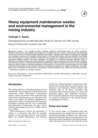
  • 10. weather), maintenance issues (e.g. engineering, scheduling, ease and frequency; and amount of sludge for further treatment/disposal), and capital cost (including installation) and operating costs (e.g. utilities, labour and chemical requirements). Numerous secondary treatment systems are available and are brie¯y discussed in this section. Coalescing or parallel plate separators operate using the same mechanism as conventional gravity separators. However, the separator's effective hori- zontal surface area (and thus ef®ciency) is increased by the installation of parallel plates in the sepa- ration chamber, without requiring an increase in the size of the separator basin. This results in (1) decrease in the space requirements for the unit, (2) a potential for an increase in the ¯ow through the unit (by 2±3 times), (3) a reduction in non-uniform, turbulent ¯ow characteristics, thus providing more favourable conditions for sepa- ration of free oil, and (4) an increase in the removal of smaller oil droplets of free oil (resulting in a lower ef¯uent concentration of oil). It also results in emulsi®ed and dissolved oils not being removed and concentrated amounts of oily products over- loading the baf¯es or plates. Parallel plates are available in modules that can usually be retro®tted into a conventional separator without major structural modi®cations. However, mechanical sludge removal equipment may also be required, to avoid having to raise the plate pack from the separator at regular intervals. Clean parallel plate separators are ef®cient systems for removing oil droplets down to 30±60 mm (compared with 150 mm for conventional gravity separators). There are numerous systems currently on the mar- ket. These have capital costs ranging from approx- imately $3±9 K (AUD) for a 1000±2000 L/hr ¯owrate. Care should be taken in selecting a system that will continue to operate reliably over a continued time- frame. Parallel plate units may experience clogging problems if the plate inclination is too shallow or the plate-to-plate spacing is too narrow. Flushing with water or air, or mechanical cleaning, may be required to clear blockages if the design or installa- tion is inappropriate, if bulk solids are not removed prior to the separator, or if the unit is not main- tained. The growth of bacteria, especially in high temperature environments, can also cause problems with coalescing plate systems, as can the generation of H2S in anaerobic conditions. Hydrocyclones increase the force for phase sepa- ration and can handle solids in the in¯uent. These are claimed to be capable of separating droplets as small as 10±20 mm. However, it is also possible to adjust the cyclones to remove smaller droplet sizes, but at an increased cost. Suppliers of liquid- liquid cyclones were identi®ed in the literature and vendor review (Anonymous, 2001a). The generic concept of the hydrocyclone system (Figure 1) is increasingly being used for treatment of light Figure 1. Flow diagram of a hydrocyclone treatment system. 10 T. F. Guerin
  • 11. and heavy vehicle washdown water and workshop wastewaters. Such systems have a capital cost of *$7±10 K (AUD) for a 2000 L/hr wastewater ¯ow- rate. However, suppliers consider that the hydro- cyclone units are comparable in cost to any coalescing plate system after 2±3 years, due to signi®cantly lower maintenance and operating costs (Anonymous, 2001a). The advantages of a hydrocyclone system include (1) they are typically less expensive to install than plate separators, (2) there are usually few (if any) issues with hazardous goods zoning (i.e. from ¯ammability), (3) ¯oating suction skimmer ensures material is fed to the cyclone from the top of the collection pit, (4) they minimize oil build-up in the collection pit (most coalescing plate separators suction off the bottom of the pit), (5) they are totally enclosed systems, (6) the cyclone action increases the droplet size distri- bution of the oil, making subsequent gravity separation more effective. For very stable emulsions, chemical treatment may be the only method for ensuring that oil can be removed from the waste stream. Chemical separ- ation can result in coalescence (formation of larger droplets) and/or precipitation (binding the oil dro- plets to a chemical ¯occulent). The former increases the volume of free oil removed, while the latter increases the volume of solids generated by the treatment process. Different chemicals, are used, depending on whether the surface charge in the emulsion is anionic, neutral or cationic (depending on the dispersing agent involved). A number of pro- prietary emulsion breakers are available through specialty chemical suppliers. Their effectiveness in speci®c situations may be determined through bench-scale treatability tests, though such tests can be very limited because of the likelihood of changes in the oily wastewater characteristics when taken from a site. Any discharge limitations on the concentrations of these chemicals and any affect on downstream biological processes should be assessed. To minimize the amount of emulsion breaker required (and thus minimize cost), additions should be made to the wastewater as far upstream of the oil-water separator as is practical, before the emul- si®ed wastewater is greatly diluted. However, if the in¯uent is pumped via high-shear pumps (which should be avoided), then emulsion breakers should be injected downstream of the pump discharge. The duration and degree of mixing of the emulsi®ed wastewater with an emulsion breaker are also critical to the cost-effectiveness of such chemical addition (API, 1990). Chemical treatment does not need to be incorporated into an existing oil/water separation system, but it is often used with dissolved air ¯otation (DAF). In ¯otation, chemicals are added to alter the surface properties (e.g. for oil emulsions) and to enhance ¯otation of suspended solids (Varadarajan and Viraraghavan, 1993). Flotation systems increase the difference in spe- ci®c gravity between the oil and water by blowing ®ne air bubbles through the wastewater. As the bubbles rise (at a rate governed by Stoke's law), they attach themselves to the oil droplets. The oil/air droplets have a lower speci®c gravity than the oil alone and rise quickly to the surface (2±3 times the rate achieved by gravity separation (Kulowiec, 1979)). The rising bubbles also transfer momentum to the oil droplets. Both of these mechanisms, which enhance the removal of oil droplets, hinder the removal of solids. The DAF process enables the separation of ®ne particulate matter, oil, emulsi®ed oil and grease from in¯owing wastewater. At speci®c times, chemical coagulants are automatically dosed into the suction line, which produce coagulation of the small particulate matter. The small bubbles, which are generated as a result of depressurization of the in¯uent, combine with the particle agglom- erates, become buoyant and ¯oat with the particu- late matter. The DAF process therefore requires that a portion of the in¯uent stream be pressurized up to 10 atm to generate the bubbles. The ¯oating mass is continually removed by a rake or skimmer and transferred to a sludge pit. When the chemical coagulant liquid aluminium sulphate is added, the acidity of the stream increases. When this coagulant is employed, caustic soda needs to be added to offset the acidity. The DAF process can handle large volumes of oily wastewater (up to 1 kL per minute, depending on the capacity of the unit). The oil in the sludge pit can then be reclaimed, treated, or recycled (Guerin et al., 1994b). There are essentially ®ve different types of ¯ota- tion systems, their classi®cation being based on the method of bubble formation (Bennett, 1988). DAF and induced/dispersed air (or gas) ¯otation are the major commercial applications. The advantages of DAF systems are that they can achieve low ef¯uent concentrations of oil and can remove very small droplet sizes (1±5 mm). However, the systems tend to be sensitive to changes in ¯owrate and in¯uent concentrations of suspended solids and oil (general- ly not economical for waste streams with oil con- centrations of b300 mg/L) (Bennett, 1988). A vapour recovery hood (or `carpet') may be also required to capture emissions (volatile organic car- bons). These systems tend to be signi®cantly more capital intensive than other oil separation systems and have high operating (chemical, labour, power and maintenance) costs. Mining industry waste and environmental management 11
  • 12. Membranes are generally regarded as polishing technologies for emulsi®ed oils. These can result in very low ef¯uent concentrations of oil (55 mg/L). The presence of free oil and large amounts of suspended solids can interfere with the operation of a membrane system. Membrane systems are also very expensive. Filter beds have been widely used in the past as secondary treatment systems. Peat, for example, has been used in a wide range of ®lter bed applications (Malterer et al., 1996). Peats with low ®bre contents and high lignin pyrolysis material and ash content have been shown to be the most effective peats to remove free and dissolved phase petroleum hydrocarbons from water (Cohen et al., 1991). Peat has the ability to both adsorb dissolved and free phase petroleum hydrocarbons from water, and provide a catalytic surface on which microbial activity can occur (Cohen et al., 1991), and it has recently been reported to be effective for petroleum hydrocarbon contaminated groundwater at the ®eld scale (Guerin et al., 2002). Retention ponds are also widely used across the minerals industry for oily wastewater separation. Many emulsions, given suf®cient time and quies- cence, will form separate oil and water layers. This is the rationale behind the use of retention dams. Retention dams provide a relatively simple concept and low cost option for secondary treatment of oily wastewater. Their use is best in arid climates and where there are large areas of land for evaporation. Such systems are, however, inappropriate where there are odorous or volatile compounds in the waste stream. Bioremediation. Land treatment, commonly known and referred to as land farming, is a widely used bioremediation process for the treatment of organic wastes. From a minerals industry perspec- tive, land treatment is particularly well suited to the treatment of oily wastewater (where the free oil has been removed), in low rainfall high evaporation (desert) climates, and where there are large areas of land available. Such environments are often present at mining operations and hence these processes have been widely adopted in the mining industry. Land treatment processes involve the application of a waste stream (typically a liquid, solid or sludge) to a shallow treatment plot. The bed is tilled regularly to aerate and mix the soil. Nutrients are applied according to their background concentrations, and the biological demand imposed by the contaminants (Huesemann, 1994). While this technology is gen- erally supported by environmental regulatory auth- orities in Australia for use in arid climates, under speci®c licensing requirements for a particular site, its deployment should only be used where alter- native secondary treatment technologies cannot be used. The limitations of land treatment processes, as applied to treatment of oily wastewater, need to be stressed to provide an overall perspective of this technology in relation to environmental manage- ment at mining operations. The limitations of land treatment technologies are as follows: Successful applications are typically in desert- like environments where evaporation rates are high and rainfall is low and soil is well drained. Loss of volatile contaminants applied in the wastes. This is only an issue where light hydrocarbon fractions (e.g. from gasoline, sol- vents, kerosene) are present in the waste stream. However, it is often dif®cult to prevent lighter hydrocarbon wastes entering the land treatment in¯uent stream and some contamination via this route is likely to occur. Potential for contaminants to leach from the treatment plots to underlying groundwater. This includes mobile hydrocarbons, detergents and metals, depending on the underlying soil type and hydrogeology. The establishment of such processes has also been viewed as forming further contaminated areas. The contaminated soil may contain metals in addition to organic contaminants. Once the mining operation has ceased, there will be contaminated soil remaining that will require responsible disposal and therefore will have an associated closure cost. Labour intensive. Land treatment facilities require ongoing supervision, maintenance and materials handling works. Contractors need to be managed and these activities incur substan- tial costs. Potential for saline conditions to develop in the land treatment soil bed. This could occur where high concentrations of salts enter the in¯uent and are left unchecked. This has not been found to be an issue (to date) from observations of land treatment facilities visited and studied by the author. Detailed operational aspects of land treatment as applied to oily wastewater and soil contaminated with organic wastes including petroleum hydrocar- bons is beyond the scope of the current paper; however, these issues are covered in detail in other scienti®c and technical papers (Elbagouri et al., 1994; Guerin, 1996; Guerin et al., 1994a; Guerin et al., 1994b; Huesemann, 1994). 12 T. F. Guerin
  • 13. Bene®ts of mechanical oil water separation systems Systems based on chemical addition or pH control tend to be more operator-intensive and more sen- sitive to ¯uctuations in ¯ow rate, contaminant concentration and temperature (Bennett, 1988). Incorporation of an equalization tank can minimize the impact and allow operation at a constant reagent dosage, or for some batch processes (e.g. truckwash), suppliers can provide rule-of-thumb tests so that operators can determine how much demulsifying reagent should be added. Given this potential sensitivity and/or increased complexity of operation, there is a trend to favour the use of mechanical separation systems. The cost of reagents (which can lead to high operating costs) and potential environmental/OHS implications resulting from reagent storage and use, also pro- vides further incentive for sites to avoid chemically- based treatment systems. Only one of the mining operations personnel contacted in the survey proposes to use chemical conditioning (in conjunction with a scraped-bottom clari®er) as a secondary treatment system to handle emulsi®ed oil (Table 5). Survey of mining operations in Asia±Paci®c region The results from the survey of other mining opera- tions are summarized in Table 5. These indicate that gravity separators are the most common tech- niques for separating oil from water. Nine of these were in operation across the 22 sites surveyed. Six of the operations surveyed used coalescing plate separators. These coalescing plate separators per- formed at varying levels of effectiveness. Retention areas (ponds) and skimmers were also commonly used with 6 of the 22 operations surveyed employing these. The ineffectiveness of the systems used was largely due to poor maintenance on the oil-water separation technology itself. It was also evident that the oil-water separation technologies were generally not maintained for optimum performance. Also, there was range of water quality targets for the ef¯uent streams for each operation, re¯ecting dif- fering regulatory and operational requirements. Common feedback from operations was that they were seeking services for improving and maintain- ing their oil-water separation and oily wastewater treatment systems. Conclusions and recommendations The following action conclusions and recommenda- tions are from the results of the study of hydro- carbon waste streams at the Australian mine, the review of literature and vendors, and the Asia± Paci®c survey. These are presented as a series of steps that could be taken by maintenance operators to enhance the management of oily wastewater at (1) the Australian mining operation and (2) more broadly at other mining operations. Importance of material balances and waste characterization Characterization of waste streams is an important ®rst step in the selection of an appropriate treat- ment technology. The design calculations for oil- water separation systems require that certain characteristics of the hydrocarbon waste stream be known. The more thoroughly the wastewater is characterized, the more predictable the perform- ance of the separation process or technology. This characterization should be conducted as part of an initial assessment or review of the oily waste man- agement system and practices at an operation. Importance of source reduction General issues Source reduction has the potential to greatly min- imize environmental impact by decreasing the volumes and changing the characteristics of the wastewaters requiring treatment. This can be achieved through proper housekeeping, equipment modi®cations, and segregation or consolidation of contaminated streams, and is critical to minimize treatment costs and the potential for environmental impact. With appropriately trained and motivated people, and appropriate equipment and systems, the production of waste can be minimized. Source reduction at mining operations can include (1) addressing technical issues such as introducing equipment for ensuring oil is captured or directed from the engine or plant to an appropriate transfer and/or storage vessel such as adaptors and connec- tors compatible with plant oil/¯uid drain outlets, and (2) addressing people issues such as chang- ing work practices to minimize contamination. Mining industry waste and environmental management 13
  • 14. Management and supervisors need to be made aware of source reduction potential and then to provide speci®c training to personnel doing the work. Sustainable solutions require effective problem solving and solution development and this can be achieved by including hydrocarbon product suppliers and waste management contractors in regular site meetings. Mining operations personnel are unlikely to have all the necessary knowledge for maximum source reduction and usually bene®t from an outside perspective. Housekeeping Where there is potential for signi®cant spills to occur (e.g. planned maintenance), oil adsorbents such as matting and/or drip trays should be con- sidered. Organic absorbent material for example can be cut to any shape, and does not generate ®ne particles (as kitty litter does), which may contam- inate `clean' systems. The absorbents can then be stored (segregated from other forms of solid waste) and incinerated. Some absorbent materials can be wrung out and reused if handled properly. A spill recovery system is also necessary where free oil is handled, and where maintenance is carried out. Vacuum systems allow oil spills to be recovered rather than emulsi®ed, are very effective, and can often incorporate intensive cleaning systems to minimize the volume of contaminated water gen- erated during spill cleanup. Sawdust or other adsor- bents may also be used to adsorb the spill, which will reduce the amount of water used during washdown. Solid wastes should be kept separate from liquid wastes. Any non-liquid and solidi®ed greases, oily rags and other solid waste (e.g. saturated adsorbent material or sawdust used to mop up spills) should be responsibly disposed of through a licensed waste contractor with current certi®cation. All staff should be trained in the use of spill response kits, and these should be located at convenient points close to potential spill locations. Also, reduc- ing the solids loading in oily wastewater can also be achieved by using an industrial vacuum system prior to a ®nal washdown. Site personnel often do not see the value in this since the washdown will achieve the same results. However, this can greatly reduce the maintenance that is required on the primary and secondary systems. Standard practices should be developed, along with a training and awareness program for opera- tors, aimed at highlighting the consequences of not following these practices. Housekeeping should also consider opportunities for the different waste streams to be combined, segregated or treated closer to the source (to prevent dilution effects). House- keeping should also be added to the agenda for the on-site meetings. Equipment and reagent modi®cation The Australian mining operation was to purchase up to 10 different degreasers. Degreaser usage appears to have decreased (between 1995 and 1996), but up to 1000 L/day (400 L/day on average) of cleansers were still being used on site during 1997. Such procurement activity is not uncommon at mining operations. Steam cleaning can reduce the presence of detergents and degreasers that, in turn, have the potential to emulsify oils in the wastewater (Guerin et al., 1994b). The survey indicated that some sites consider steam cleaning to present unacceptable OHS hazards, especially for heavy equipment. There are numerous opportuni- ties at mining operations for deploying innovations, technologies and practices for management of oily wastewater streams. Segregation and consolidation of contaminated streams Wastewater treatment facilities are best operated with a relatively constant ¯owrate of water, rather than having to deal with ¯ows that always vary. Collection structures should be evaluated to deter- mine if the water entering treatment systems can be minimized. Waste streams, which are generated at irregular intervals, could be combined with other streams after primary treatment. Technology selection The expected ef¯uent qualities provided by supp- liers should only be used as a guide for technology selection. This data is based on ideal operating conditions and does not necessarily hold for very complex waste streams. Site-speci®c testwork is recommended if stringent treatment targets (530±50 mg/L oil) are required. Recommendations for the Australian Mining Operation Ef¯uent discharge requirements for the operation are 10 mg/L of oil in water (NEPC, 1999). This value could be achieved by the use of the conventional gravity separators in conjunction with a secondary 14 T. F. Guerin
  • 15. treatment technology. Individual technologies would need to be adjusted to provide the necessary discharge limits once they were installed. In terms of cost effectiveness, the most appropriate means of achieving this is to optimize the existing conven- tional gravity separators at the site, and explore means of reducing the oil loadings into the waste stream. By reducing the quantities of oily waste- water reaching the land treatment facility, this will help to ensure that the land treatment faci- lity will continue to operate effectively over the life of the mine. Consolidation of the range of cleansers used would assist in minimizing the amount of oil emul- si®cation occurring in the oily wastewater stream. Quick break detergents could be used to replace the older generation of hard detergents, which form very stable oil-in-water emulsions. Oil droplet size analysis could be conducted on representative sam- ples of oily wastewater from the ef¯uent stream from the site. This will provide more de®nitive information on the nature of the oily wastewater and would assist in determining which treatment technologies would be most appropriate. A secondary treatment system could also be installed for treating the oily wastewater ef¯uent from the gravity plate separators such as a hydro- cyclone system, or a retention dam. Retention dams would be an appropriate technology because of the high rates of evaporation at the site. These recommendations will also be applicable to other mining operations with related maintenance waste streams in arid climates. Acknowledgements Colleagues in Rio Tinto Technical Services, in particular Stuart Rhodes, who have assisted the author in under- standing and developing the issues covered. The opinions expressed in this paper are the authors own and do not necessarily re¯ect those of Shell Engineering Limited. References Anonymous (1992). Standard methods for the enumera- tion of water and wastewater APHA, AWWA, WEF, Washington, D.C. Anonymous (2001a). [http://www.bakerhughes.com/ bakerprocess and www.spinifex-group.com.au]. Anonymous (2001b). [http://www.abanaki.com/oilfacts. html#SEC5]. Anonymous (2001c), [http://www.globalspill.com.au/ incinerators/enviro.html]. API (1990). Design and operation of oil-water separators American Petroleum Institute (API). Washington, D.C. Bennett, G. F. (1988). The removal of oil from waste- water by air ¯otation: a review. CRC Critical Reviews in Environmental Control 18, 189±253. Cohen, A. D., Rollings, M. S., Zunic, W. M. and Durig, J. D. (1991). Effects of chemical and physical differences in peats on their ability to extract hydrocarbons from water. Water Resources Research 25, 1047±1060. Elbagouri, I. H., Elnawawy, A. S., Abdal, M., Al Daher, R. and Khalafawi, M. S. (1994). Mobility of soil and other sludge constituents during oily sludge treatment by landfarming. Resources Conservation and Recycling 11, 93±100. Ford, D. L. (1978). Technology for removal of hydro- carbons from surface and groundwater sources. In Oil in Freshwater: Chemistry, Biology, Countermeasure Technology (J. H. Vandermeulen and S. E. Hruey, eds). New York, NY: Pergamon Press. Gopalratnam, V. C., Bennett, G. F. and Peters, R. W. (1988). The simultaneous removal of oil and heavy metals from industrial wastewater by joint precipita- tion and air ¯otation. Environmental Progress 7, 84±92. Guerin, T. F. (1996). Selecting the appropriate techno- logy for treating a contaminated site or waste stream. Australian Journal of Mining 11, 82±86. Guerin, T. F., Horner, S., McGovern, T. and Davey, B. (2002). An application of permeable reactive barrier technology to petroleum hydrocarbon contaminated groundwater. Water Research 36, 15±24. Guerin, T. F., Rhodes, S. H., Kelley, B. C. and Peck, P. C. (1994a). The application of bioremediation to the clean-up of contaminated sites: the potential and limitations. In Contaminated Soil, Royal Australian Chemical Institute (RACI) Industrial Chemist Com- mercial Services Group in conjunction with the University of Newcastle, Newcastle, NSW Guerin, T. F., Rhodes, S. H., Leiner, C., Hammerschmid, K., Roden, S., McAllister, P. J., Peck, P. C. and Kelley, B. C. (1994b). Management and treatment of wastes from maintenance operations in the mining industry. In Maintenance in the Mining and Metallurgical industries (A. Hargreaves and J. Montegner, eds), The Australasian Institute of Mining and Metallurgy and The University of Wollongong, Wollongong. Huesemann, M. H. (1994). Guidelines for land-treating petroleum hydrocarbon-contaminated soils. Journal of Soil Contamination 3, 299±318. Kulowiec, J. J. (1979). Techniques for removing oil and grease from industrial wastewater. Pollution Engi- neering February, 49±52. Malterer, T., McCarthy, B. and Adams, R. (1996). Use of peat in waste treatment. Mining Engineering January, 53±56. NEPC (1999). National environmental protection measureÐschedule b (1) guidelines on the investiga- tions levels for soil and groundwater. Adelaide: NEPC (National Environmental Protection Council). Scott, M. J. and Jones, M. N. (2000). The biodegradation of surfactants in the environment. Biochim Biophys Acta 1508, 235±251. USEPA (1983). Methods for chemical analysis of water and wastes. Environmental Monitoring and Support Laboratory, Of®ce of Research and Development, U.S. Environmental Protection Agency, Cincinnati. Varadarajan, R.andViraraghavan, T.(1993). Dissolved air ¯otation in water and wastewater treatment. Indian Journal of Environmental Protection 13, 103±108. Mining industry waste and environmental management 15