
Recomendados
Mais conteúdo relacionado
Semelhante a Bridge rf cal sheet 0 1
Semelhante a Bridge rf cal sheet 0 1 (20)
Último
Último (20)
Bridge rf cal sheet 0 1
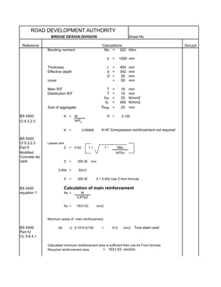
- 1. ROAD DEVELOPMENT AUTHORITY BRIDGE DESIGN DIVISION Sheet No. Reference Calculations Out put Bending moment Mx = 202 kNm b = 1000 mm Thickness t = 400 mm Effective depth d = 342 mm d' = 50 mm cover = 50 mm Main R/F =T 16 mm Distribution R/F =T 10 mm = fcu 25 N/mm2 fy = 460 N/mm2 Size of aggregate hagg = 20 mm BS 5400 K = M K' = 0.156 Cl 5.3.2.3 bd2fcu K = 0.06908 K<K' Compression reinforcement not required BS 5400 Cl 5.3.2.3 Leaver arm Eqn:5 Z = 0.5d 1+ 1- 5Mu Modified bd2fcu Concrete tec clark Z = 309.35 mm 0.95d = 324.9 Z = 309.35 Z < 0.95d Use Z from formula BS 5400 Calculation of main reinforcement equation 1 As = M 0.87fyZ As = 1631.63 mm2 Minimum areas of main reinforcement BS 5400 As ≥ 0.15*b*d/100 = 513 mm2 Tore steel used Part IV CL 5.8.4.1 Calculated minimum reinforcement area is sufficient then use As From formula Required reinforcement area = 1631.63 mm2/m
- 2. ROAD DEVELOPMENT AUTHORITY BRIDGE DESIGN DIVISION Sheet No. Reference Calculations Out put Main R/F use T 16 123.28 mm Distance 4.9 inch T 16 100 Actual reinforcement area A = 2011.43 mm2/m Calculation of secondary reinforcement B.S 5400 As ≥ 0.12bd/100 Part IV As = 410.4 mm2/m CL 5.8.4.2 use T 10 191.45 mm Distance ### inch T 10 200 Actual reinforcement area A = 392.86 mm2/m B.S 5400 Maximum reinforcement area in member Part IV As ≤ bh*4/100 CL 5.8.5 = 16000 mm2 Therefore Condition satisfies Calculation of reinforcement for cmpression zone B.S 5400 Part IV Provide minimum of main reinforcement for compression zone CL 5.8.4.2 As ≥ 0.12bd/100 Therefore provide = 410.4 mm2/m use T 12 275.69 mm Distance ### inch T 12 200 B.S 5400 Minimum distance between bars ≥ hagg + 5 mm Part IV CL:5.8.8.1 ≥ 25 mm Condition satisfies B.S 5400 Check for shear resistance Part IV cl:5.3.3.1 Ultimate shear force V = 83.5 kN/m Shear stress ν = V bd = 0.2442 0.75 fcu = 3.75 0.75fcu>v condition satisfied for maximum shear
- 3. ROAD DEVELOPMENT AUTHORITY BRIDGE DESIGN DIVISION Sheet No. Reference Calculations Out put 0.27 100 As 1 B.S 5400 Vc = ( f cu ) 3 Part IV γ m bw Table 8&9 Vc = 0.529 N/mm2 Depth factor ξ s = (500 / d )1 / 4 or 0.70, whichever is the grater ξs = 1.100 ξs vc = 0.582 N/mm2 ν < ξ s v c Condition satisfied Check for crack width control Moment at servicibility limite state SLS = 122.42 kNm Copressive strength fcu Static Modulus ( Ec) N/mm2 kN/mm2 kN/mm2 20 25 21 to 29 25 26 22 to 30 30 28 23 to 33 40 31 26 to 36 50 34 28 to 40 60 36 30 to 42 Actual R/F use T 16 100 mm Distance As = 2011.43 mm2 No compression reinforcement Єc fcb x h d Єs fs Є1 Actual Steel area As = 2011.43 mm2
- 4. ROAD DEVELOPMENT AUTHORITY BRIDGE DESIGN DIVISION Sheet No. Reference Calculations Out put Grade of concrete Fcu = 25 N/mm 2 Static moduulus of concrete Ec = 26 Consider half modulus = 13 KN/mm2 Es = 200 KN/mm2 α = Es/Ec = 15.38 propotion of reinforcement φ = As/bd = 0.00588 Depth to neutral axis Step 1 x = αφ 1+ 2 - 1 d αφ X = 117.80 mm Step 2 z = d - x/3 = 302.73 mm Step 3 Steel stress fs = M AsZ = 201.05 N/mm2 fs < 0.87fy pass Step 4 Concrete stress fcb = 2M xbz = 6.87 N/mm2 fcb < 0.45fcu pass Step 5 Є1 = fs h-x
- 5. ROAD DEVELOPMENT AUTHORITY BRIDGE DESIGN DIVISION Sheet No. Reference Calculations Out put Es d-x = 0.001265 Step 6 Єs = fs Es = 0.001005 B.S 5400 Part IV 3.8bt h( a ' − d c ) Mq −9 equation 25 ε m = ε1 − 1 − 10 ε s As ( h − d c ) Mg but not greater than ε1 Where 3.8bt h( a ' − d c ) Mq −9 ε2 = 1 − 10 ε s As (h − d c ) Mg ε1 - is the calculated strain at the level where cracking is being considered, ignoring the stiffening effect of the concrete in the tension zone; bt - is the width of the section at the level of the centroid of the tension steel; a' - is the distance from the compression face to the point at which the crack width is being calculated; Mg - is the moment at the section considered due to permanent loads; Mq - is the moment at the section considered due to live loads; εs - is the calculated strain in the tension reinforcement, ignoring the stiffening effect of the concrete in the tension zone; As - is the area of tension reinforcement. Live Mq = 120.00 KNm Dead Mg = 2.42 KNm Є2 = -0.04 mm Єm = Є1 - Є2 = 0.0377247 mm Є2<0 so tht Єm=Є1
- 6. ROAD DEVELOPMENT AUTHORITY BRIDGE DESIGN DIVISION Sheet No. Reference Calculations Out put Єm = 0.00127 mm = d-x r acr acr = 68.58 mm Step 8 Design crack width = 3acrЄm 1 + 2(acr-cnom)/(h-dc) BS 5400-4 Table-1 where Severe acr is the distance from the point (crack) condition considered to the surface of the nearest bar which controls the crack width; Cnom is the required nominal cover to the outermost reinforcement given in Table 13; where the cover shown on the drawing is greater than the value given in Table 13, the latter value may be used; dc is the depth of the concrete in compression (if dc = 0 the crack widths should be calculated using equation 26); h is the overall depth of the section; Єm is the calculated strain at the level where cracking is being considered, allowing for the stiffening effect of the concrete in the tension zone; a negative value of Єm indicates that the section is uncracked. The value of Єm should be obtained from the equation: Therefore design crack width = 3acrЄm 1 + 2(acr-cnom)/(h-dc) 0.2300 < 0.25mm Crack width ok
- 7. ROAD DEVELOPMENT AUTHORITY BRIDGE DESIGN DIVISION Sheet No. Reference Calculations Out put